
Abstract
In this paper, a serial reconfigurable modular robot is presented. Each module is a cubic structure. Each surface of this cube has a connection interface. It has three rotational degrees of freedom, which are distributed along the three directions of its local coordinate system. A new and reliable docking mechanism is designed to realize the connection among adjacent modules. With the novel structure, the vibration of the modular robot is negligible. Then, based on the characteristics of the module, an eigenvector to describe the state information of a single module and an adjacency matrix to express the topology structure of a multi-module system are defined. Based on the screw theory, a kinematic model of the serial modular robot is proposed. Using an exponential product formula, the modular expressions of the kinematic equations are obtained automatically. According to the motion characteristics of each module and the structure characteristics of the modular robot, we can simplify the module which provides redundant degrees of freedom to a connecting rod. This method can reduce the complexity of solving the inverse kinematic solution. To solve the inverse kinematics automatically, we decompose it into two sub-motion models and propose the conditions of applying the subproblem method. Finally, a simulation by MATLAB is used to verify the correctness of the automatic generation of the forward and inverse kinematics.
Introduction
A reconfigurable modular robot system is a complex system that consists of several basic modules. These basic modules can be rearranged to form different configurations to adapt to different environments and tasks. In order to meet the requirement of rapid assembly, it is very difficult for the docking device of modular robots to achieve high rigidity, which could cause non-negligible residual vibration when the robot is working. 1 Specifically, if the robot consists of numerous modules, the residual vibration may be accumulated and amplified, which is very harmful to the robot’s motion accuracy and service life. 2 In 2006, Chen et al. proposed a method for vibration suppression of flexible arm based on the state feedback control, 3 but this method has high requirements on the sensor system. In 2018, Gao et al. proposed a method to reduce vibration through structure optimization using an optimization algorithm, 4 but its effect is very limited. In this paper, with a new type of docking mechanism the vibration in the modular robot is greatly suppressed.
Generally, each module includes an independent drive unit, a battery unit, and a control system, and a host computer is responsible for the reconfiguration and motion planning of the multi-module system. Through some innovative software, interfaces, and actuators, it is easy to customize the multi-module system with various functions. 5 Due to their capability of adapting themselves to the external environments, reconfigurable modular robots have great application in such occasions as planetary exploration, nuclear-plant maintenance, or some rescue missions in places inaccessible to humans. 6
In 1998, the first reconfigurable modular manipulator system was developed by the University of Carnegie Mellon. 7 In 2001, another RMMS named Skyworker was proposed by the Robotics Research Institute of Carnegie Mellon University, which was designed to assemble components of large size on the track. It achieved the function of walking on the truss by holding the truss with friction. 8 For the same purpose of assembling large components on the orbit, in 2002, the Japanese space development agency proposed the Orbital Servicing Vehicle(Hyper-OSV). It adopted the modularization conception. Hyper-OSV consisted of many modules with unified interfaces. These mechanical arms can be disconnected from and reconnected with the base to reconfigure as a space robot with different functions. 9 It was also in 2002, AIST developed Modular Transformer (M-TRAN) and Modular Transformer II (M-TRAN II). These robots can change their configurations by themselves. With the help of the different polarity of magnet, they realized the function of connection and disconnection. 10 Obviously, such a connection method makes it difficult to bear large work load. Subsequently, the improved Modular Transformer III (M-TRAN III) adopted a mechanical connection mechanism, 11 and its bearing capacity had been improved significantly. In 2006, Shen et al. designed a hyper redundant manipulator named Superbots. Each module has three degrees of freedom (DOFs). It can be reconfigured with different functions with different connecting modes. 12 In recent years, some interactive modular robotic systems, such as Ani-Bot, were proposed. They allowed users to control their DIY robots using mixed-reality interaction. 13 To enhance the capabilities in the docking as well as navigation in co-ordinated structures such as humanoid robots, HexaMob adopted vision sensors. 14 This is a trend in the field of reconfigurable modular robots.
However, it is difficult to quickly establish kinematic equations for different configurations of modular robots. Therefore, the method of establishing kinematic models based on the screw theory and applying an exponential product method to derive kinematic equations has received more and more attention. 15 Fei et al. had carried out a research on the automatic generation of the forward kinematics and inverse dynamics of the modular robots, 16 but she did not consider that the drive units in different modules might affect the system’s motion. Lv had derived the solution of the inverse kinematics of robots with traditional structure based on Wu’s method and the screw theory. Lv’s method is easily programmed and can be applied to solve the kinematic problems of other robot systems such as parallel robot systems. According to the kinematic model of a four-leg robot, Zhuang and Huang used the screw theory to analyze the inverse solution to the single-leg serial subsystem and the forward solution to the parallel body subsystem, and verified the correctness with some simulations on MATLAB and ADAMS. 17 Zhang used the screw theory to analyze the forward kinematics of tandem robots of closed chains and proposed a method to establish the kinematic equations of tandem robots of closed chains based on the screw theory. 18 However, their analysis on solving inverse kinematic problems is inadequate.
In this paper, a reconfigurable modular robot system is proposed. A new type of hole and shaft docking mechanism is introduced. The mathematical description of the single module and the adjacency matrix of the multi-module system are defined. The motion ability of the module is analyzed. Kinematic models based on the screw theory are established. On this basis, with the exponential product formula and two subproblems, a method of automatically generating the forward and inverse kinematics of the serial module robot is proposed and verified.
Structure of module
Structure and function
The module is designed as cubic structure (Figure 1). There are six connection interfaces on each of the six surfaces of the cube, among which three interfaces are rotatable. They are the output shaft of the driving mechanism in fact and are distributed in the three directions of its local coordinate system. The other three connection interfaces are fixed on the frame. It means that these interfaces are not rotatable. When the axes of the two connection interfaces coincide, the docking mechanism can achieve the axial and circular fixation, so that the connection and driving function between the two modules are realized. The mass of each module is 1.5 kg and the maximum length is 209 mm.
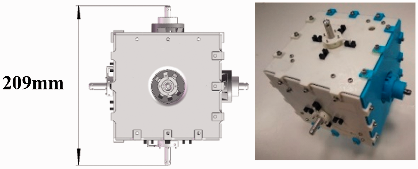
Frame structure.
Docking mechanism
The modules connect with each other in the form of shaft and hole. The rotatable connection interfaces of the module are the end part of the module’s output shaft (Figure 2(a)). The other kind of connection interface consists of a docking sleeve and a guide rod. The docking sleeve device can slide on the guide rod as shown in Figure 2(b). The whole interface is fixed on the frame structure. 19
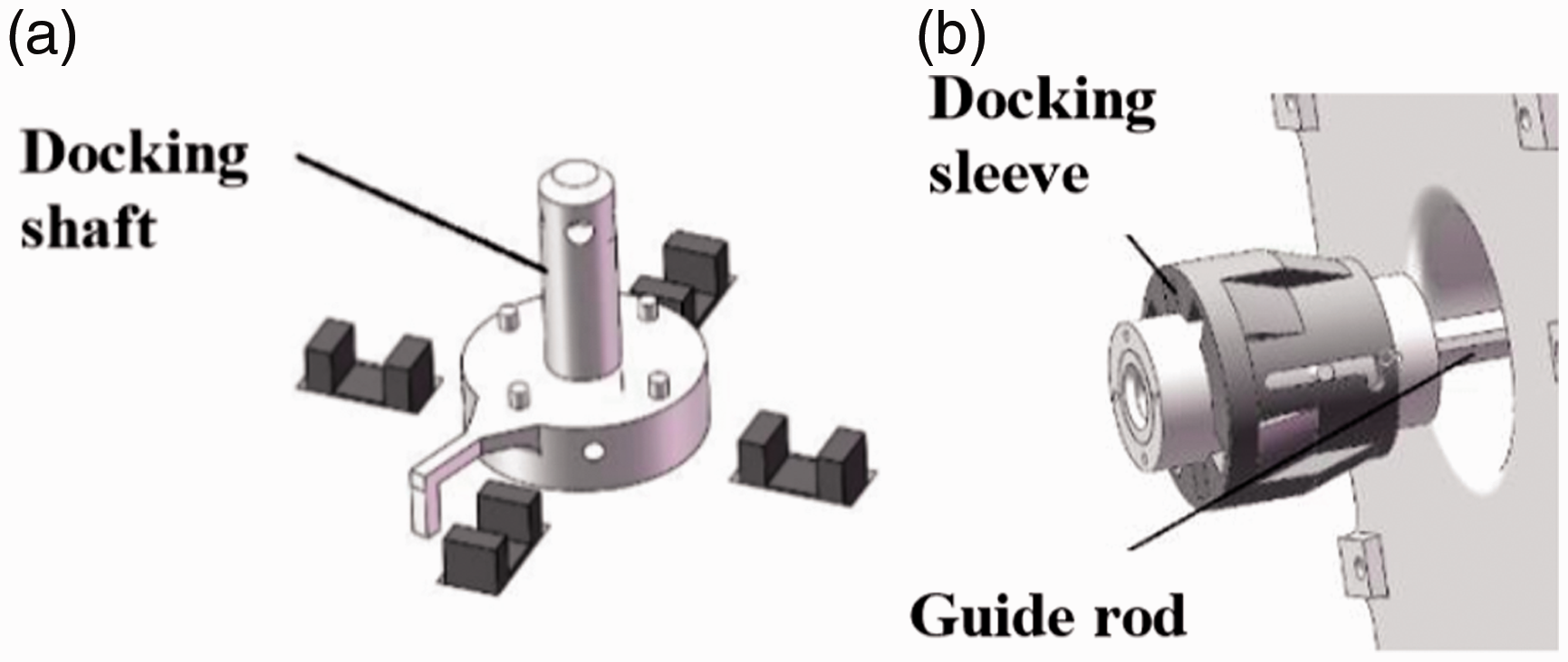
Docking mechanism.
When docking, the module rotates to the position where the axes of the two connection interfaces coincide. Then the docking sleeve is pushed outward along the guide rod till it contacts with the baffle (Figure 3(a)). At this position, the cylinder pins with flat heads in the docking sleeve device are just aligned with the pin holes of the guide rod and the docking shaft. Then, the shell of docking sleeve is pushed outward again (Figure 3(b)), and the inclined plane inside the shell will push these cylinder pins into corresponding pin holes. Finally, the docking process is completed (Figure 3(c)).
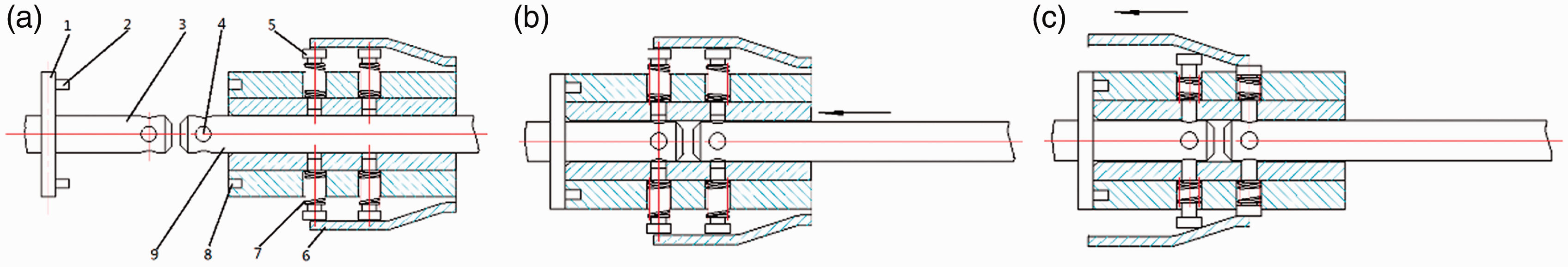
Docking process. 1. baffle, 2. dowel pin, 3. docking shaft, 4. pin hole, 5. cylinder pin, 6. shell of docking sleeve, 7. spring, 8. location hole, 9. guide rod.
In order to ensure that the cylinder pins are coaxial with the pin holes during the docking process, four location holes are arranged at the end of the docking sleeve, and dowel pins are arranged at the corresponding position of the baffle. When pushing the docking sleeve outward and inserting the dowel pins into the location holes, the cylinder pins inside the sleeve must be coaxial with the location holes. Thus, the sleeve shell can push the cylinder pins into the pin holes smoothly. 20 Figure 4 shows the state of connection of two modules.
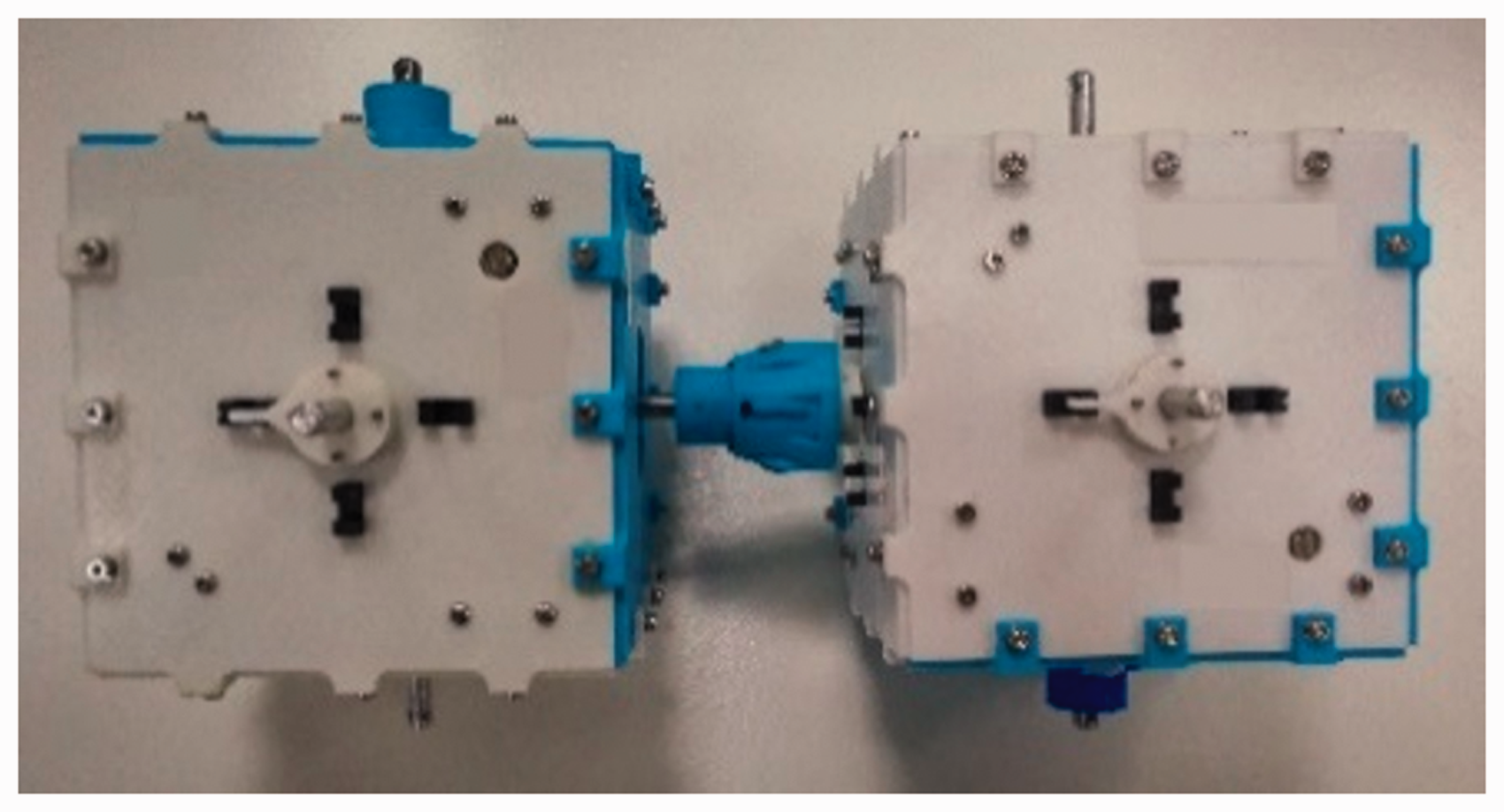
State after docking.
The flexibility of robots mainly comes from two aspects: joint flexibility and link flexibility. When robots are working with high acceleration, such flexibility may cause vibration problems. However, unlike industrial robots, the speed of this modular robot is relatively low. And through precise assembly of shafts and holes, the novel docking mechanism can achieve highly rigid connection between adjacent modules. Moreover, the structure of this modular robot is also very compact due to the special structure. Thus, the whole modular robot is of high rigidity, which can minimize the vibration. Also, the docking shaft and the guide rod of the docking mechanism are made of graphite fiber reinforced Mg-matrix composite, 21 which can increase the damping factor of the structure and absorb the limited vibration. Thus, no obvious vibration will be caused in this modular robot. Through tests, the vibration in this modular robot can be negligible.
Drive mechanism
Each module has three independent and identical drive mechanisms (Figure 5). The power source of the drive mechanism is a motor with a worm reducer. Its rated torque is 0.75 N ⋅ m and can realize the self-locking function without power. A pair of deceleration gears with a reduction ratio of 121:17 is responsible for increasing the torque. Therefore, the theoretical output torque of each drive mechanism is as follows

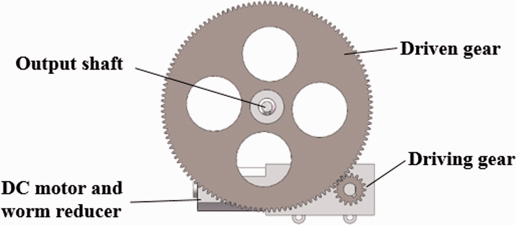
Drive mechanism.
Mathematical description
Expression of single module
For a single module, we can use an eigenvector to set up the only mathematical description

To simplify the simulation and communication, we define an ID number for each module. Here, we use
The spatial state information of a module consists of the position coordinate and the angle coordinate in the absolute coordinate system
Finally,
The number of the surfaces.
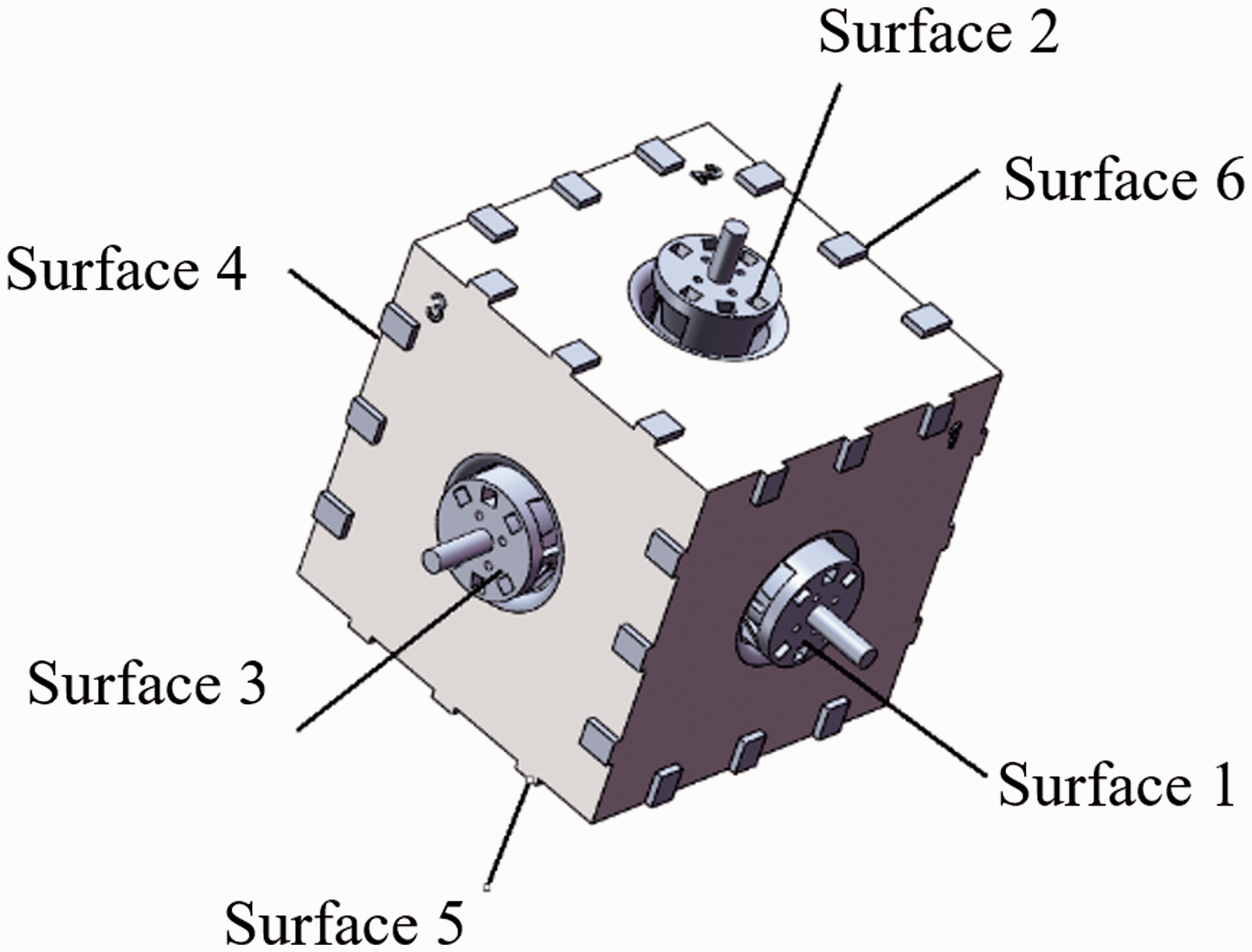
The local coordinate system at the centroid of each module is set up and its x-axis, y-axis, and z-axis point to the surfaces 2, 1, and 6, and the absolute coordinate system

A multi-module system.
Expression of multi-module system
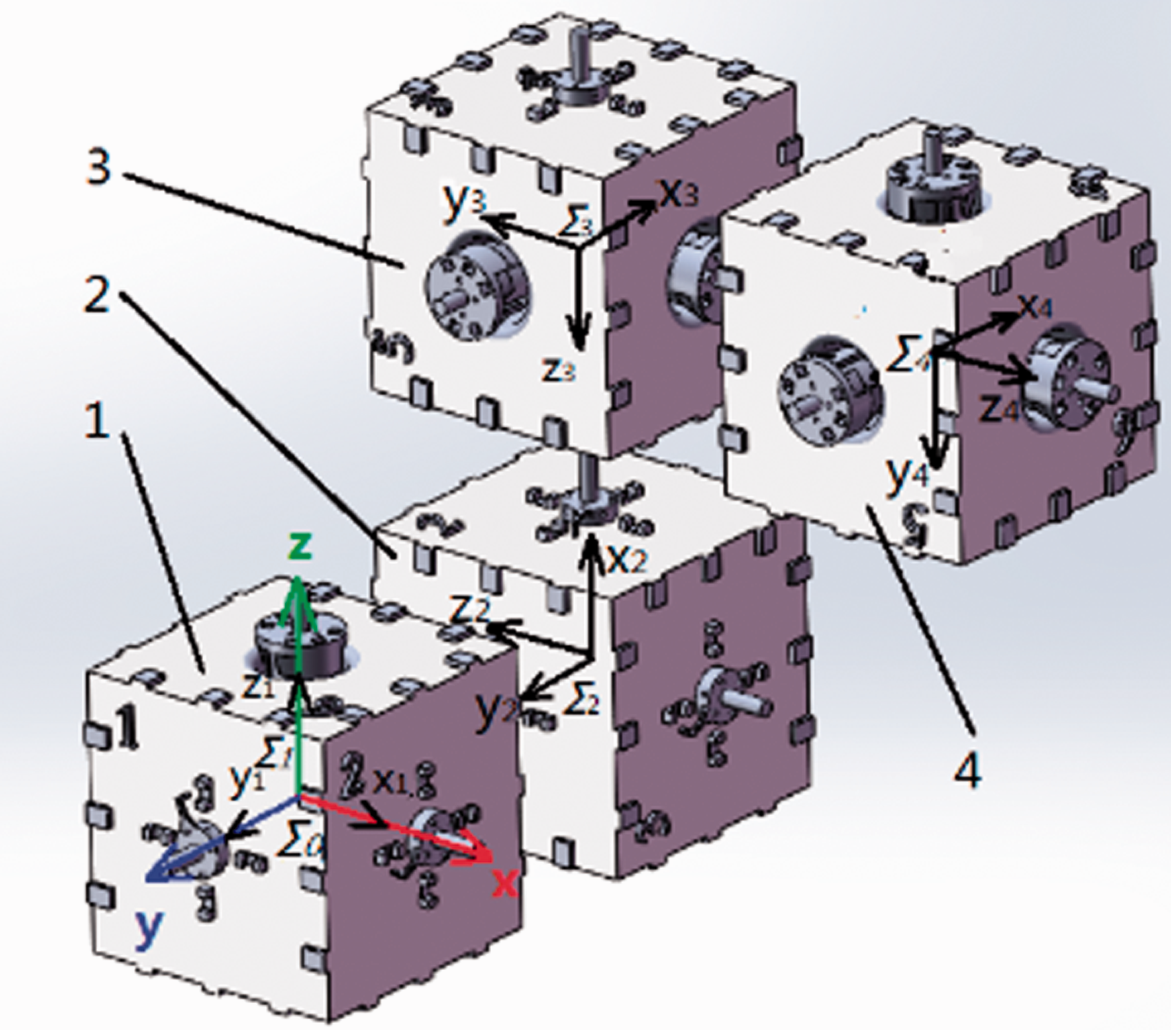
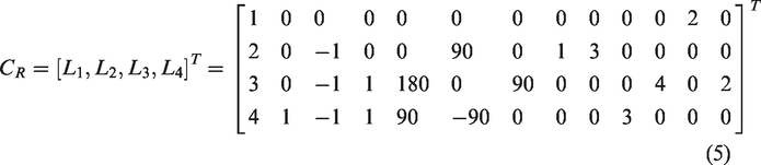
On the basis of the single module, we can get the mathematical expressions of a multi-module system by combining all the modules’ eigenvectors together according to their ID numbers. This adjacency matrix includes all the information of the multi-module system and only one system can be expressed by this adjacency matrix. For a configuration R with n modules, its state information can be expressed as an adjacency matrix with a dimension of 13×n

Therefore, the adjacency matrix of the multi-module system in Figure 7 can be expressed in the following form
Forward kinematics
The serial modular robot system is composed of multiple cubic modules, every module has six ports, each port is located in the center of six surfaces of the cubic module (Figure 8). Among the six ports, Port 1, Port 2, and Port 3 can drive shafts. Port 4, Port 5, and Port 6 are fixed ports. A local coordinate system
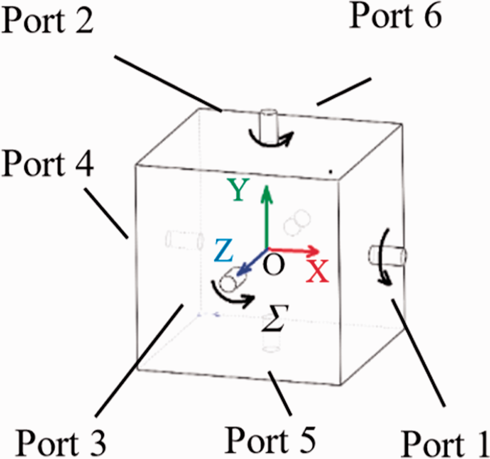
Cubic module.
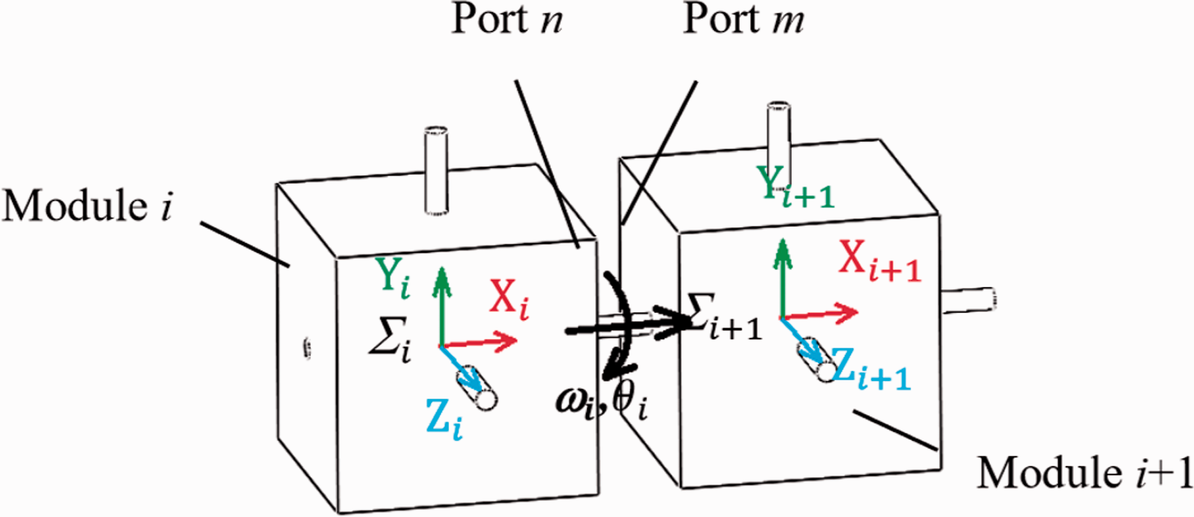
Connection of two modules.
Modular representation of kinematic equation
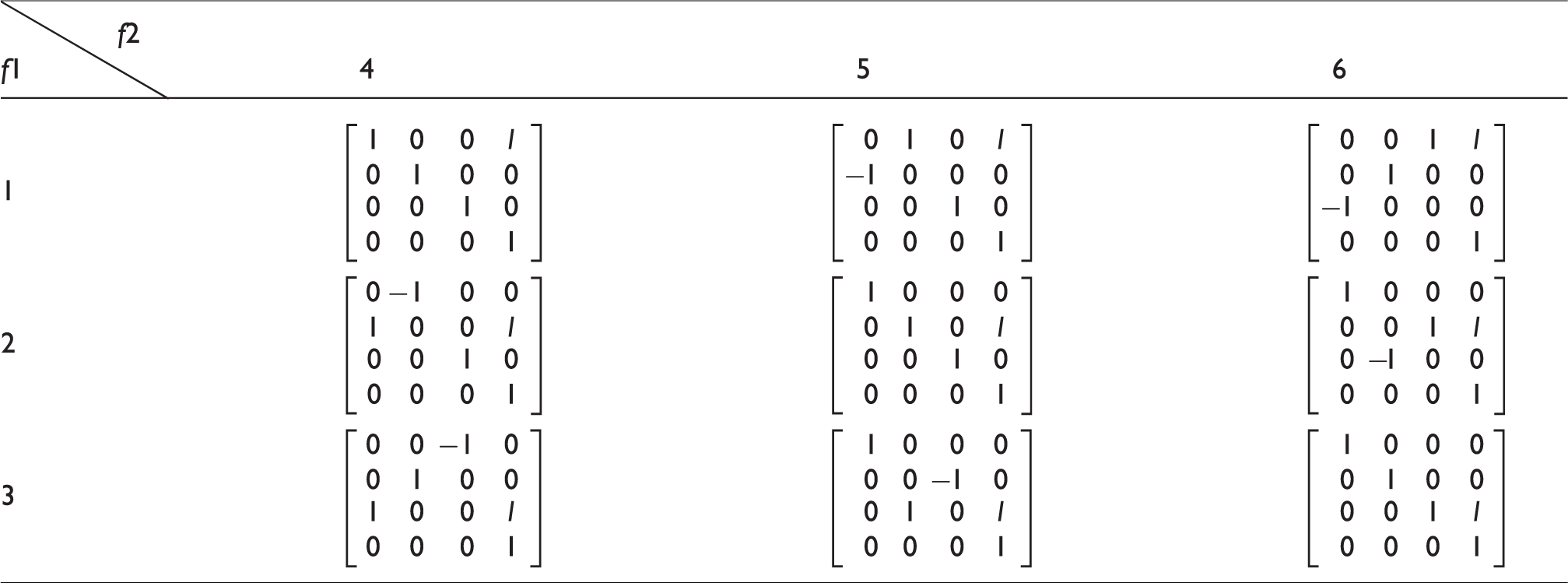
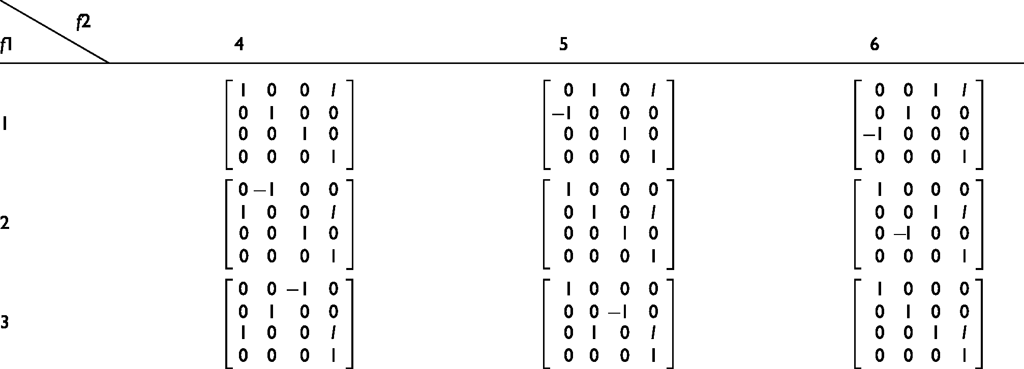
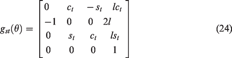
When Module i is connected to Module i + 1, the distance between the centers of two modules is constantly l. The pose matrix of Module i in the local coordinate system of Module i + 1 depends on the connection ports and the rotation angle at the connection interface. The zero rotation angle is defined as the position where the local coordinate systems of two docking modules are parallel (Figure 9). Then the pose matrix of Module i + 1 in

Here,
Value of
Forward kinematics of serial module robot
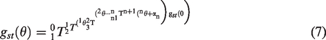
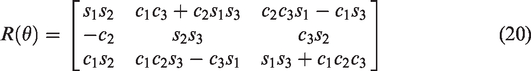
For a modular robot with n + 1 modules, the solution of forward kinematics is given as
Inverse kinematics
Analysis of subproblems
For the motion of a cubic modular robot with only rotational joints, it can be decomposed into two types of sub-motions. In Figure 10(a), the rotation of a point p to a point q under the influence of a screw
(1) Subproblem 1: A point 
Find a point on 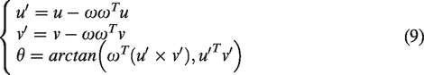
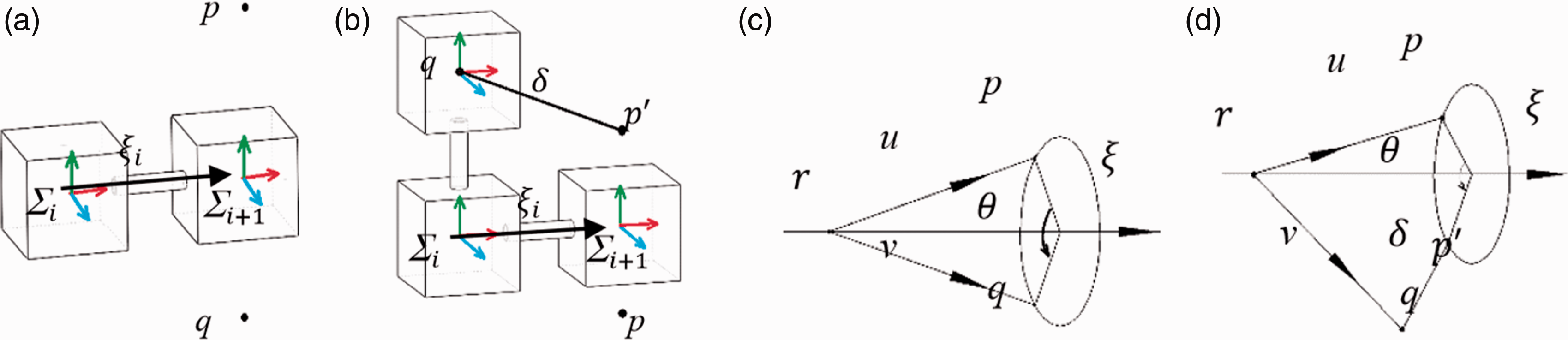
Two subproblems of rotational joints: (a) Sub-motion 1, (b) Sub-motion 2, (c) Sub-motion 1, and (d) Sub-motion 2.
If
(2) Subproblem 2: A point 
By finding a point r that is located on 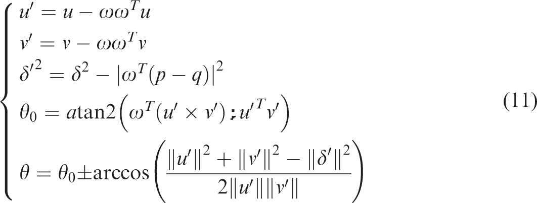
In this equation,
Conditions of existing solution
Whether the method of subproblems can be used to derive the analytical solutions to the inverse kinematic problems depends on whether the inverse kinematic problems can be decomposed into one or multiple subproblems.
Due to the unique structure of the cubic module, in the configuration of the serial module robot, the connection type of the ith module can be classified into three types (Figure 11).
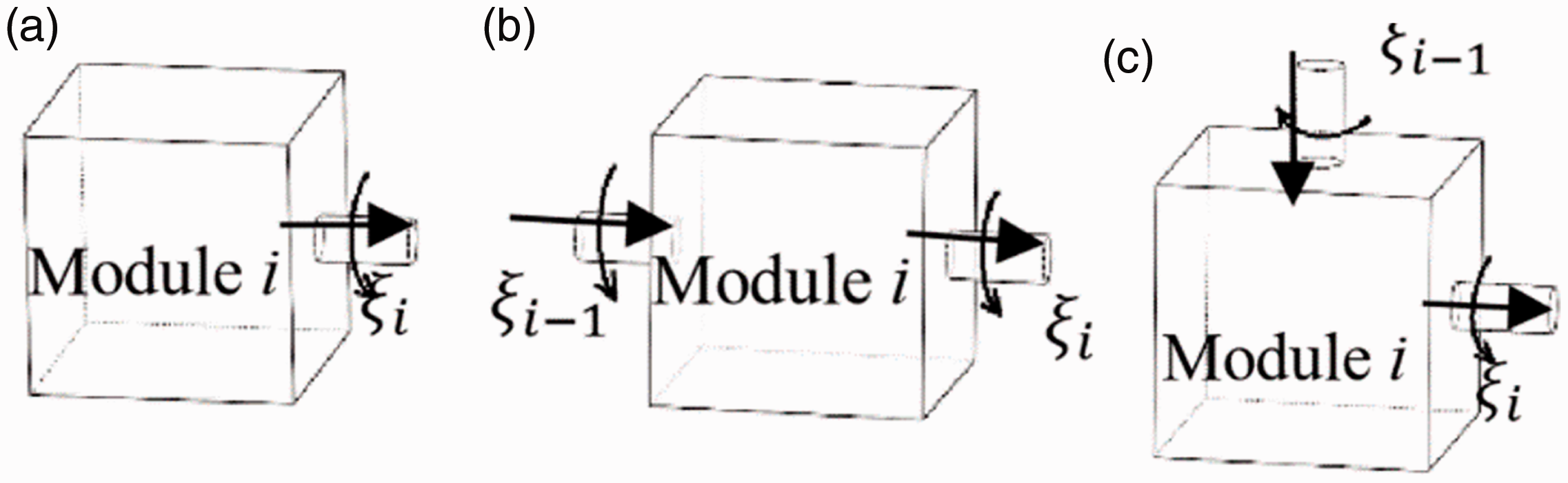
Three connection types of cubic module: (a) single connection (Type 1), (b) two aligned connection (Type 2), and (c) two vertical connection (Type 3).
For Type 2 as shown in Figure 11(b), the twist 
When 
Due to the particular module connection method, there are no three consecutive intersecting twists
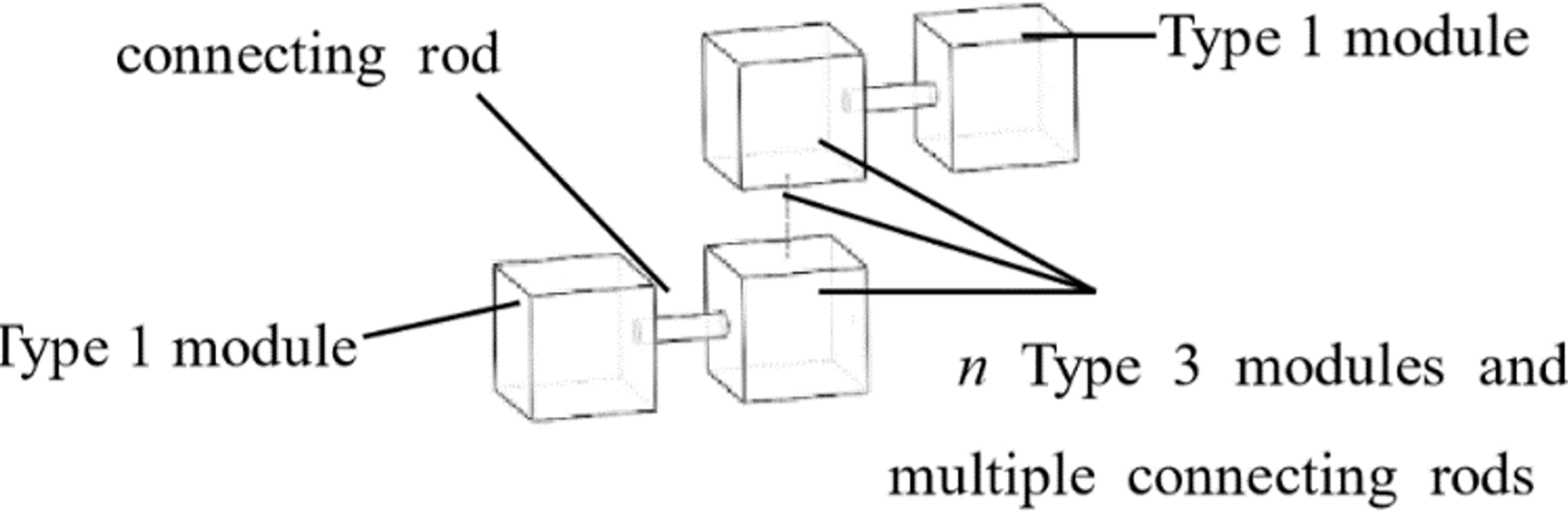
Simplified modular robot.
Inverse kinematics with subproblems
The solution to inverse kinematics of a module chain with less than four Type 3 modules can be derived by decoupling the module chain into one or multiple subproblems.
Figure 12 shows a simplified configuration of any modular robot containing four Type 3 modules. When the pose of the end module 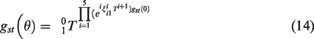
In the equation, 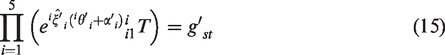
Through post-multiplying both sides of equation (15) by the intersecting point 
By taking norms on both sides of equation (16) after it minuses the intersecting point 
In accordance with Subproblem 2,
When 
The above process uses subproblems to solve the inverse kinematics of modular robots that can be simplified as the configurations shown in Figure 13. When the number of Type 3 modules in the modular robot is less than three, this method can be performed to derive solutions to inverse kinematics.
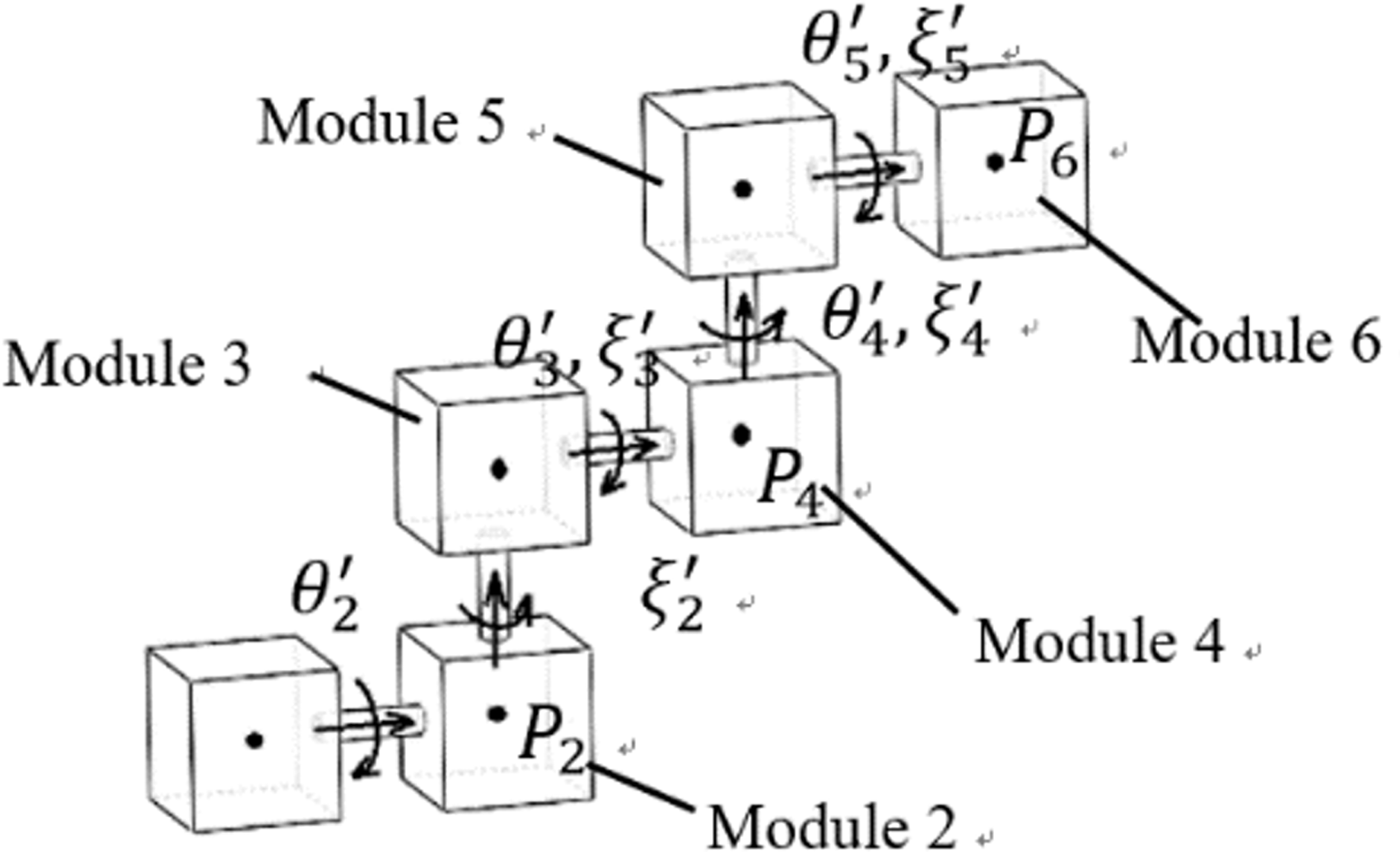
Modular robot with four Type 3 modules.
Thus, if the initial state and topological relationship of each module in the modular robot are given, the analytical expression of forward kinematics of the modular robot can be automatically generated. At the same time, solutions to inverse kinematics of configurations with less than four Type 3 modules can be automatically generated with the subproblem method.
Simulation and verification
Simulation on forward kinematics
The solution to forward kinematics in the previous section is verified through MATLAB.
According to the modular robot shown in Figure 14, the absolute coordinate system
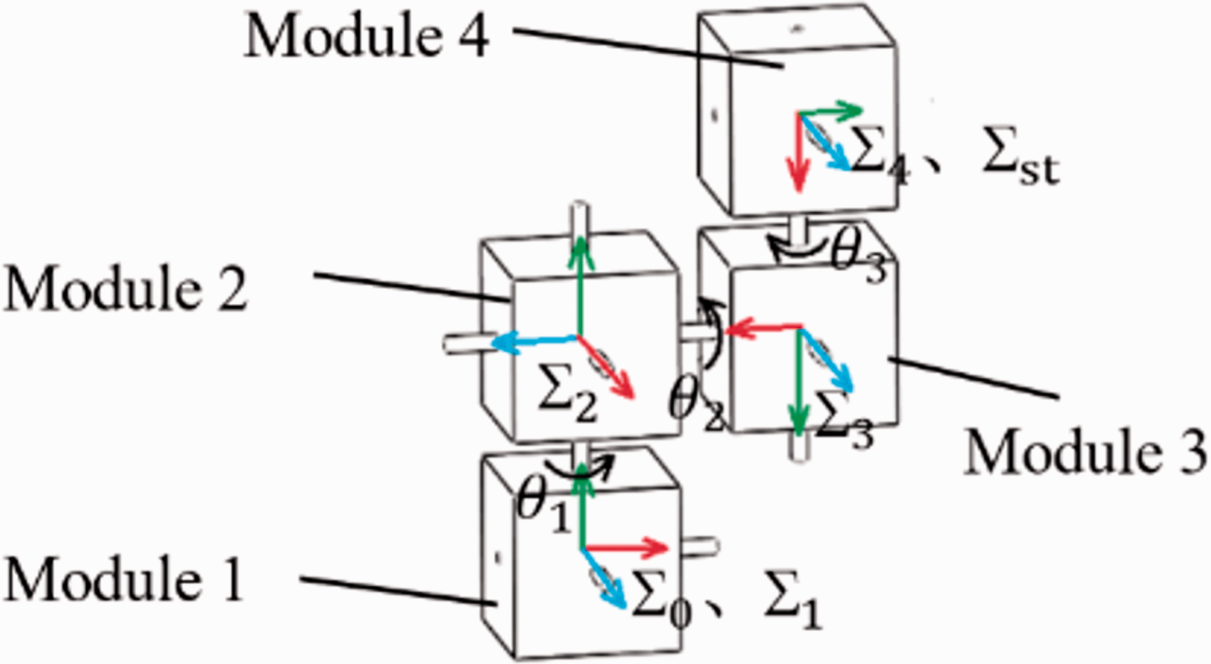
Serial modular robot.
Topological relationship.
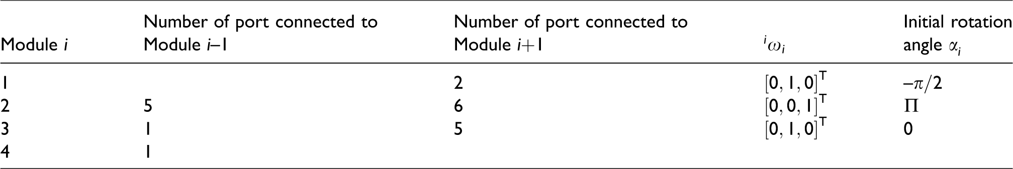
By taking 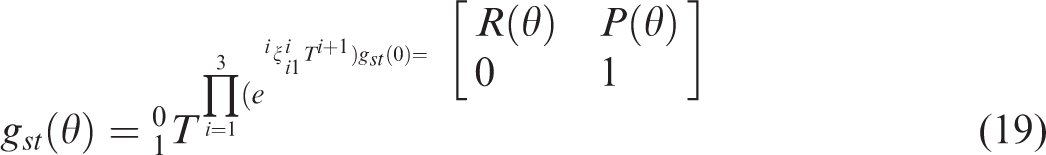

In the above equations,
After determining the connection of the modules, let l = 1. And the motion of the joint space of the module chain is defined as 
The trajectory of equation (18) is drawn with MATLAB. At the same time, a simulation on the module chain in Figure 14 with the same parameters is performed on MATLAB (Figure 15).
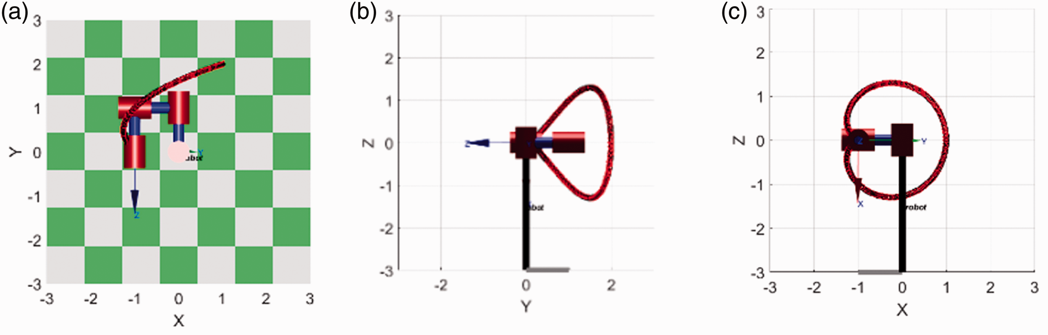
Forward kinematic trajectory: (a) x–y plane, (b) y–z plane, and (c) x–z plane.
The trajectory (Figure 15) obtained by the simulation indicates that the automatic generation of forward kinematics is correct.
Verification of inverse kinematic solution
Let the motion of the modular robot in Figure 14 be
Then the objective pose of the tool coordinate system is
By post-multiplying equation (19) by the coordinate of the centroid 
After selecting a point from twist 

By substituting equation (19) into the above equations and multiplying it by 
After selecting a point from twist 
By substituting 
After selecting a point from twist 
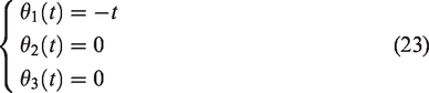
In summary, through the subproblem method the following solutions are obtained

The results are consistent with given equation (23), which indicates that the solution derived from automatic generation of inverse kinematics is correct.
Conclusions
This paper introduces the structure of a cubic reconfigurable modular robot and the work principle of its docking mechanism in detail. Through novel structure and the application of fiber reinforced polymer, the vibration of the modular robot is reduced to negligible range. By setting up the eigenvector of a single module and the adjacency matrix of the multi-module system, we can describe the complex relationships of the multi-module system clearly and its basic motion ability is analyzed. Based on the specific modular robot, the modular representation of kinematic expressions by an exponential product formula is realized. Under the precondition that the topological relationship and the rotation angle of the initial state of the modular robot are known, an automatic generation method for the kinematic expression of the serial modular robot is proposed. The motion characteristics of the module and the configuration characteristics of the modular robot are analyzed to obtain the method to simplify the modular robot. This simplifies multiple continuous rotational DOFs in the same direction to a single degree of freedom, and thus significantly reduces the complexity of solving the inverse kinematic problems. This paper also discusses the conditions of applying subproblems to solve the inverse kinematics of the modular robot. It is shown that for a modular robot containing no more than four Type 3 modules, it can be decomposed into one or several subproblems to calculate the inverse solution. In the last section, this paper uses MATLAB to obtain a forward kinematic simulation and an inverse kinematic calculation according to a 3-DOF modular robot, which verifies the correctness of the forward and inverse kinematic solution.
Footnotes
Declaration of conflicting interests
The author(s) declared no potential conflicts of interest with respect to the research, authorship, and/or publication of this article.
Funding
The author(s) disclosed receipt of the following financial support for the research, authorship, and/or publication of this article: This research is supported by Shanghai Aerospace System Engineering Institute Space Fund (USCAST2016-30).