
Abstract
In order to study the shaft system vibration of mixed-flow pump under rotor–stator interaction, the unsteady pressure fluctuation characteristics are measured and the rotor axis orbit obtained based on the Bentley 408 data acquisition system. The relationship between pressure fluctuation and vibration characteristics of shaft system at the blade passing frequency is analyzed. The results show that the pressure fluctuation amplitude is the largest and the rotor–stator interaction effect is the most obvious in the middle of the impeller. Along the direction of the main stream, the velocity energy is converted into pressure energy, the rotor–stator interaction effect is gradually weakened, and the main frequency of the pressure pulsation gradually turns from the 4X frequency to the 1X frequency of the impeller rotation frequency. The hydraulic stirring vibration and other factors lead to jagged sharp corners on the original axis orbit. The axis orbit of 1X frequency is an ellipse with little difference between long and short axis while the 2X frequency is the opposite, from which the existence of arcuate rotary whirl and misalignment phenomenon of the rotor can be judged. Combined with time–frequency characteristics of pressure pulsation, it can be found that the hydraulic imbalance has a great influence on the vibration of the shafting, while the rotor–stator interaction at the blade passing frequency takes the second place, which is the main factor of inducing the 4X frequency vibration of the axis orbit. This study targets is that providing practical guidance for improving operation stability and preventing the vibration failure of the mixed-flow pump.
Introduction
Mixed-flow pump is extensively used in agricultural irrigation, water supply and drainage, circulating water system of mine and nuclear power stations, and other fields, which plays an important role in economic construction. 1 With the increase of hydraulic machinery size, capacity, and rotation speed, the unsteady pressure fluctuation caused by the rotor–stator interaction between impeller and guide vane will cause cyclical hydraulic radial force and axial force in the system. The resulting unbalanced hydrodynamic force will cause the vibration and noise of shaft. When the problem gets serious, resonance will occur and cause unit failure.2–4
At present, a lot of research has been conducted on the pressure pulsation characteristics of the mixed-flow pump through a large number of experimental methods and numerical calculation.5,6 Tsukamoto et al. 7 studied the pressure pulsation in the impeller of centrifugal pump with guide vane. It was observed that the pressure fluctuation is larger when the radial gap between impeller and guide vane is small. Arndt et al.8,9 paid attention to the rotor–stator interaction effect between the impeller and the guide vanes, and discussed the influence of the rotor–stator interaction on the pressure fluctuation by matching different number of guide vanes. Li et al. 10 studied the effect of the thickness of the guide vane on the internal pressure pulsation of the mixed-flow pump. They conducted that the thickness of the guide vane has little influence on the pressure fluctuation at the inlet of the impeller and has the greatest influence on the pressure pulsation in the middle of the guide vane. Khalifa et al. 11 focused on the pump vibration of the blade passing frequency induced by the pressure fluctuation in the double channel pump. Zhang et al. 12 explored the influence of tip clearance on pressure fluctuation in low specific speed mixed-flow pump passage. Also, Zhang et al. 13 explored the pressure fluctuation characteristics in a mixed-flow pump handling a gas–liquid two-phase flow with ANSYS CFX for the whole flow passage when the inlet gas void fraction was 0, 5, and 10%, respectively. But these literatures just reveal the internal unsteady flow fields and the shaft vibration caused by the hydraulic factors is not studied.
The axis orbit was showing the shaft vibration and it was combined by the two direction vibration. Further, it is an important symptom in diagnosing the condition of a hydraulic machine. Nowadays, most of the researchers are working on axis orbit by means of this experiment. Berot and Dourlens 14 compared centerline orbit of the shaft of the original and modified overhung centrifugal compressors. Two conditions are found, a circular orbit and a centered orbit, at the inboard bearing. If one of these two conditions is not met, the spiral vibration does not occur. Ren and Qu 15 present the identification of shaft centerline orbit for wind power units based on Hopfield neural network, and experiment’s results show that SA-Hopfield identification model performed better than the previous methods. Adewusi and Al-Bedoor 16 studied on the dynamic response of an overhung rotor with a propagating transverse crack by analyzing the Bode plots, frequency spectrum cascades, frequency spectrum waterfalls, and orbits. It was observed that the propagating crack produces changes in vibration amplitudes of 1X and 2X vibration harmonics and excites 3X harmonic just before fracture. Žarko et al. 17 measured shaft orbit of a salient-pole synchronous generator and the unbalanced magnetic forces are calculated using the finite element method. The results showed that the induced stator winding currents can be established in both the no-load and loaded condition. Muszynska 18 explored the fact using experiment test and found that with a specific imbalance distribution along the rotor axis, it can happen that a portion of the rotor processes forward while another one processes backward. The results above focus more on the characteristics and causes of the pressure pulsation and the vibration characteristics of the rotor of nonhydraulic machinery, but there is little research on the relationship between the pressure pulsation and the vibration of the shafting of the mixed-flow pump.
Therefore, the objectives of this study are to reveal the relationship between the shaft vibration and rotor–stator interaction in the mixed-flow pump. The high precision pressure sensor is used to collect the test data of pressure fluctuation of mixed-flow pump in the design condition at different axial positions. Based on the Bentley 408 data acquisition system, the vibration of the rotor shaft is studied. The time–frequency characteristics of pressure pulsation and axis orbit are analyzed emphatically, and the relationship between the pressure fluctuation of the blade passing frequency and the vibration characteristics of the rotor shaft is discussed. In order to reduce the vibration of shaft which is caused by rotor–stator interaction between the guide vane and the impeller in the hydraulic design of mixed-flow pump, it will need theoretical observation.
Experimental system
Experimental model
The parameters of the mixed-flow pump model in this research are as follows: design flow rate Qdes = 380 m3/h, head Hdes = 6 m, rotating speed ndes = 1450 r/min, specific speed ns=480, number of impeller blades Z = 4, number of guide vanes Zg = 7. The mixed-flow pump model is shown in Figure 1.
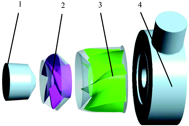
Mixed-flow pump model. 1. Inlet part; 2. impeller; 3. guide vane; 4. annular volute.
Experimental apparatus
The experimental measurements were conducted using Φ250 mm stainless steel closed test rig of mixed-flow pump in Research Center of Fluid Machinery Engineering and Technology, Jiangsu University. The test bench meets the accuracy requirement of first class, and the experiment equipment is shown in Figure 2. The test rig is mainly composed of control valve, turbine flow-meter, regulator tank, booster pump, inlet and outlet pressure sensor, torque tachometer, model pump, etc. The regulator tank is used to supply water and harmonize system pressure and the booster pump is primarily used for pressurizing when the model pump speed is too low.
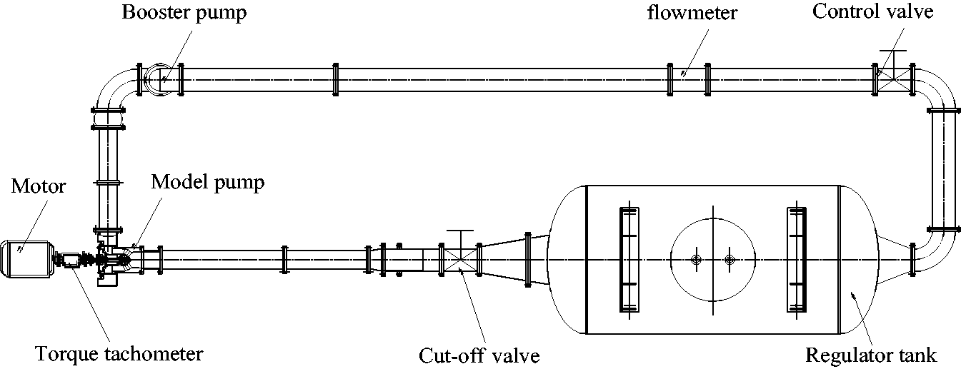
Experimental setup.
The energy performance parameters of the model pumps are measured by different devices. The ZJ-type torque tachometer produced by Shanghai-Standard Intelligent Terminal Co Ltd, with precision 0.2, was used for the torque and the tachometric measurement; the LWGY-type turbine flow-meter produced by Shanghai ZiYiJiu Automatic Instrumentation Co Ltd, with precision 0.5, was set in the system to measure the flow rate; besides, the MPM-type pressure sensor produced by Mike Co Ltd, with 0.5% FS precision, was equipped at the inlet and outlet of the mixed-flow pump to measure the pressure. Finally, the HSJ-2010 hydraulic machinery tester was used to acquire experimental data from the above-mentioned sensors and all the signals were then transported from HSJ-2010 hydraulic machinery to the computer.
Experimental method
At the beginning stage of the experiment, the pump testing system was started and then the supporting software was debugged and recorded the experimental data while keeping the test bench outlet valve fully opened. After that converter started to rotate the motor. Outlet valve was adjusted to make the flow-meter reading meet the design flow rate condition value (Qdes = 380 m3/h). When the rotating speed stabled at 1450 r/min, the energy parameters and pressure fluctuation data were obtained separately. At the same time, the Bentley 408 data acquisition system should be also started and triggered to record the vibration signals of the rotor. After getting the experimental data from mixed-flow pump, the power source is turned off and waited until all fluid in the pipe line becomes stabled. The above-mentioned experiment was repeated three times.
Pressure pulsation experiment
So as to study the characteristics of the pressure fluctuation which is induced by the interaction between the guide vane and the impeller in the mixed-flow pump which is to be designed under flow rate condition, the experiment focused on the pressure fluctuation characteristics of the impeller inlet (monitor position A), the middle of the impeller (monitor position B), the impeller outlet (monitor position C), the inlet of the guide vane (monitor position D), the outlet of the guide vane (monitor position E), and the pump unit outlet (monitor position F). So collecting the flow information at different positions, six pressure monitoring sensors were separately attached which are to be used to capture the different hydraulic pulsation source and it causes the low frequency vibration of the impeller and the guide vane. The arrangement of the monitoring points is shown in Figure 3. The monitoring point F was placed on the outlet of the pump unit, and all monitoring points are on the axis horizontal plane. The monitor position F is not shown in the figure.
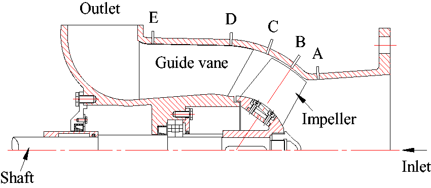
Position of pressure pulsation monitoring points.
Axis orbit experiment
The Bentley 408 data acquisition system was used to quantify the vibration of the rotor shaft under the designed flow condition. The system consisted of 408 dynamic signal processing equipment (DSPi) and ADRE Sxp software. The 3300 XL 8 mm eddy current displacement sensor used in the experiment was composed of probe, proximate, and extension line. The diameter of the probe is 8 mm, the type of probe is 330130-040, the type of proximitor is 330180-50, the extension of the cable is 4 m, and the metal for calibration is No. 45 steel. The gap voltage of the sensor is −10 V, the sensitivity of No. 45 steel is 7.87 V/mm, the range is −2 mm to +2 mm. The sensor is installed at the midpoint of the line so that the measurement range is equal in positive number and negative number. A digital multimeter was installed at the OUT terminal of the proximitor. Observe the output voltage of the OUT and COM terminal when the probe is screwed into the hole. Fix the sensor when the voltmeter is −10 V so that the sensor is installed at the middle point of the line. The keyphase sensor used in this experiment was an infrared sensor. This sensor is only used to stick the luminous on the rector and its probe must be installed at the perpendicular of the rector. In order to exclude the influence of the driving device, the power supply and ground wire of the eddy current displacement sensor are independent and not shared with the electric motor. And the electromagnetic interference is also considered, therefore the drive device power of the electric motor is more than 10 m away from the eddy current displacement sensor. Double-stranded double-layer shielding cable is adopted in the eddy current displacement sensor, which can protect the measuring signal doubly.
Because the rotary error of the mixed-flow pump rotor was much larger than the roundness error, the shape error of the rotor shaft can be ignored. The vibration of the rotor was measured by bidirectional dynamic measurement in this experiment. 19 According to the experimental requirements, the data acquisition and detection system was connected, and the monitoring points of the axis orbit are selected on the side of connection of the rotor shaft coupling and the electric machinery. Eddy current displacement sensor and keyphase were installed according to requirements and then be linked up to Bentley 408 data acquisition system. The eddy current displacement sensor was vertically intersected with a distance of 1 mm between the probe and the rotor. The keyphase is vertically installed on the rotor shaft, and between the reflective paper and the rotor shaft was 5 mm. The measurement method and the experimental arrangement of the axis orbit are shown in Figure 4.
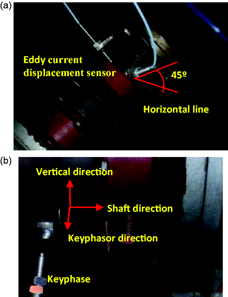
Measurement of rotor axis locus. (a) Position of eddy current displacement sensor and (b) position of keyphase.
Experimental results and analysis
Reliability experiment verification
So as to verify the reliability of the test rig and the experimental method, three groups of experimental data on energy performance of mixed-flow pump model are acquired, which is shown in Figure 5. It can be found in the experimental results that the head and efficiency curves of the three experiments are generally the same, which proves that this test has good repeatability and high reliability. At design flow rate condition, the average head is 5.53 m, and the average efficiency is 64%. The range of high-efficiency areas is wide and high-efficiency points are biased toward large flow conditions.
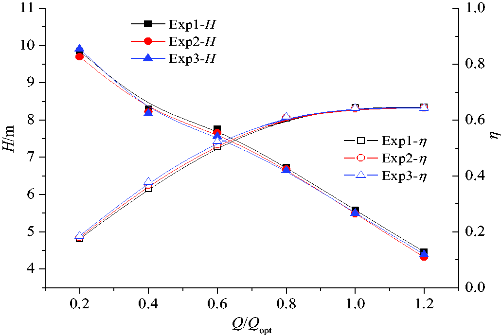
Energy performance of mixed-flow pump.
Characteristics of pressure pulsation
In order to eliminate the influence of the static pressure at the measuring point on the analysis of the pressure pulsation, pressure pulsation at different positions is compared. The pressure coefficient Cp is used to represent the pressure amplitude variation with respect to time, and this coefficient represents only the degree of pressure pulsation. The expression of pressure coefficient Cp is
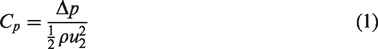
Figure 6 illustrates the time-domain diagram of the pressure fluctuation of each point in one rotating cycle of the impeller under the condition of 1450 r/min rotational speed. As can be seen from the results that the impeller inlet makes four peaks in one rotation, the same number of impeller blades, i.e. the pressure pulsation cycle T = 90°. The wave was similar to sine wave, and the rotor–stator interaction is obvious. At the B position of the impeller, the pressure fluctuation intensity was the largest and highest value of pressure fluctuation goes up to 0.72, and the pulsation is strongly coupled. At the same time, due to existence of tip leakage in the vortex blade, there are two peak value in the pressure fluctuation waveform (as shown in the figure of the circular dashed line); due to pressure divergence between pressure surface and suction surface of impeller make the amplitude of pressure decline and rapidly rise. As the fluid comes out from the impeller rotation field, there are some changes in the amplitude of pressure fluctuation at the C position as interaction area of the outlet impeller and guide vane inlet was slightly lower than the middle of the top of the blade. The pressure coefficient Cp fluctuates in the range of 0.15. However, the amplitude of the pressure fluctuation waveform is still large due to the rotor–stator interaction between the impeller and the guide vanes. With gradual decline of the influence of impeller rotation in the internal flow field, the fluctuation pressure at the middle of the guide vane D and the outlet of the guide vane F seems a minor periodicity, but passing frequency of blade is prevailing now. Then compared with the interaction flow field, the amplitude of pressure fluctuation was further reduced. At the outlet of the pump device F, the pressure fluctuation in the impeller rotation cycle presents a little periodicity and the amplitude was higher than that of guide vane. Due to pump outlet area being smaller than the annular volute cross-sectional area, internal multiple scale vortex of annular volute creates a collision at the outlet and conducts static and dynamic conversion, which leads to be a large pressure fluctuation that was the most probable cause.
Time-domain diagram of pressure pulsation at monitoring points.
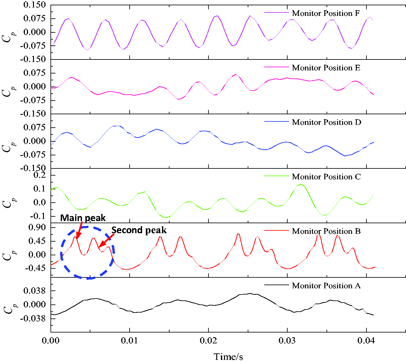
Because the number of impeller blades is Z = 4 and the impeller speed is n = 1 450 r/min, the impeller rotation frequency is calculated to be 24.17 Hz, and the blade passing frequency is 96.67 Hz. By means of fast Fourier transform, the amplitude of harmonic components and frequency distribution of pressure fluctuation can be obtained. Figure 7 illustrates the frequency domain of pressure fluctuation. In the pressure pulsation of the fluid, the influence frequency of impeller blade on fluid should be Z times of the rotation frequency and its harmonics.
Frequency-domain diagram of pressure fluctuation.
It can be seen from the frequency distribution of the pressure fluctuation that at the inlet of the impeller A, the pressure pulsation in the low frequency section has four peaks due to the influence of the number of blades and the inlet prewhirl flow field. The maximum peak of pressure coefficient appears in the 2X frequency of the impeller rotation frequency, and Cp is about 0.0175. In the middle of the impeller B, the pressure fluctuation amplitude is the largest. At this time, the main frequency of pressure pulsation is about 95 Hz, which is the 4X frequency of the rotation frequency of the impeller. The secondary main frequency is 190 Hz, that is the 8X frequency of the rotation frequency of the impeller. And the rotor–stator interaction effect of impeller and guide vane is the most obvious now. When the fluid enters the area between the impeller outlet and the inlet of the guide vane, the main frequency of the pressure fluctuation changes into 8X frequency of the rotation frequency of the impeller and the secondary main frequency is the same as the blade frequency. In the guide vane inlet D and the guide vane outlet E, because the guide vane has the function of collecting the fluid energy, the velocity of the fluid can be transformed into the pressure energy, and the influence of the rotor–stator interaction between the impeller and the guide vane is gradually weakened. Impeller rotation frequency is the dominant frequency of the pressure fluctuation in this area, and the pressure coefficient Cp is about 0.022. In the outlet of the mixed-flow pump, because the exit flow field is influenced by the combined action of the annular chamber structure and the outflow instability, the main frequency of pressure pulsation is 8X frequency of the impeller rotation frequency. Therefore, the pressure pulsation produced by the rotor–stator interaction effect between the impeller and the guide vane had an important influence on the impeller region, and the impeller rotation frequency has an important influence on the pressure fluctuation of the impeller inlet, guide vane inlet and outlet.
Characteristics of shaft system vibration
The vibration of the rotor is obtained under the design flow rate condition, and the magnitude of rotor vibration is represented by the axis orbit of the rotor. As a kind of important graphic symptom of the rotor vibration state, the axis orbit contains a large number of fault information, which is an effective way to visually reflect the actual motion of the rotor.20–23 The time-domain diagram of the axis orbit can reflect the change of the vibration quantity with time, and the frequency spectrum can reflect the frequency component of the complex signal.
In the processing of the axis orbit signal, the Butterworth filter is used to filter the original signal and get the 1X and 2X frequency of the rotor axis orbit. The characteristic of the Butterworth filter is that the frequency response curve in the passing frequency band is maximally flat without fluctuation, while the frequency response curve in the blocked frequency band gradually decreases to zero. The relationship between the square of the amplitude of the Butterworth filter and the frequency can be expressed as follows
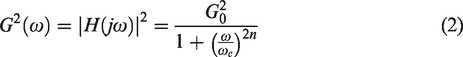
By means of Laplace transformation, set s = σ + jω and in the two-dimensional complex plane it can be concluded that

From the general nature of Laplace, it can be known that s = jω,
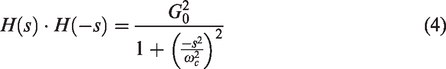
The pole of the above-mentioned function is equally distributed on the circle whose radius is ωc. Therefore, equation (5) can be derived
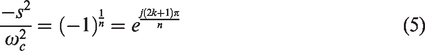

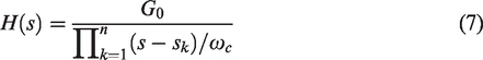
The transfer function can be represented by these poles, and equation (7) is shown as follows
The original axis orbit of mixed-flow pump rotor in a time of Δt = 0.3 s is measured, as shown in Figure 8. From the figure, the original axis orbit is not an ideal smooth and flat circular, but a nearly the shape of “8” with many jagged sharp corners. According to the research literature of rotating machinery fault,24–28 this characteristic of the rotor shows that there is a typical misalignment fault. Because the test points are very close to the bearing, the fault is possibly caused by the alignment problem between the rotor and the supporting bearing. Meanwhile, there are many zigzagged sharp corners in the banding axis orbit diagram, which indicates that the higher harmonic signals exist in the original axis orbit signals. The causes of these influences on the axis orbit may be the hydraulic exciting vibration and noise when the mixed-flow pump operates. From the time-domain diagram of the axis orbit in X direction and Y direction, it can be found that the time-domain diagram of the axis orbit in X direction is periodic distorted sinusoidal wave while the time-domain diagram of the axis orbit in Y direction is periodic distorted cosine wave and the phase difference of the axis orbit time-domain diagram between the X direction and Y direction is exactly 1/4 cycle due to the eddy current sensors being installed 90° perpendicular to each other. There are two times frequency peaks in the time-domain waveform in the two directions, which indicates that there is also a hydraulic imbalance in rotor or a misalignment of the rotor.
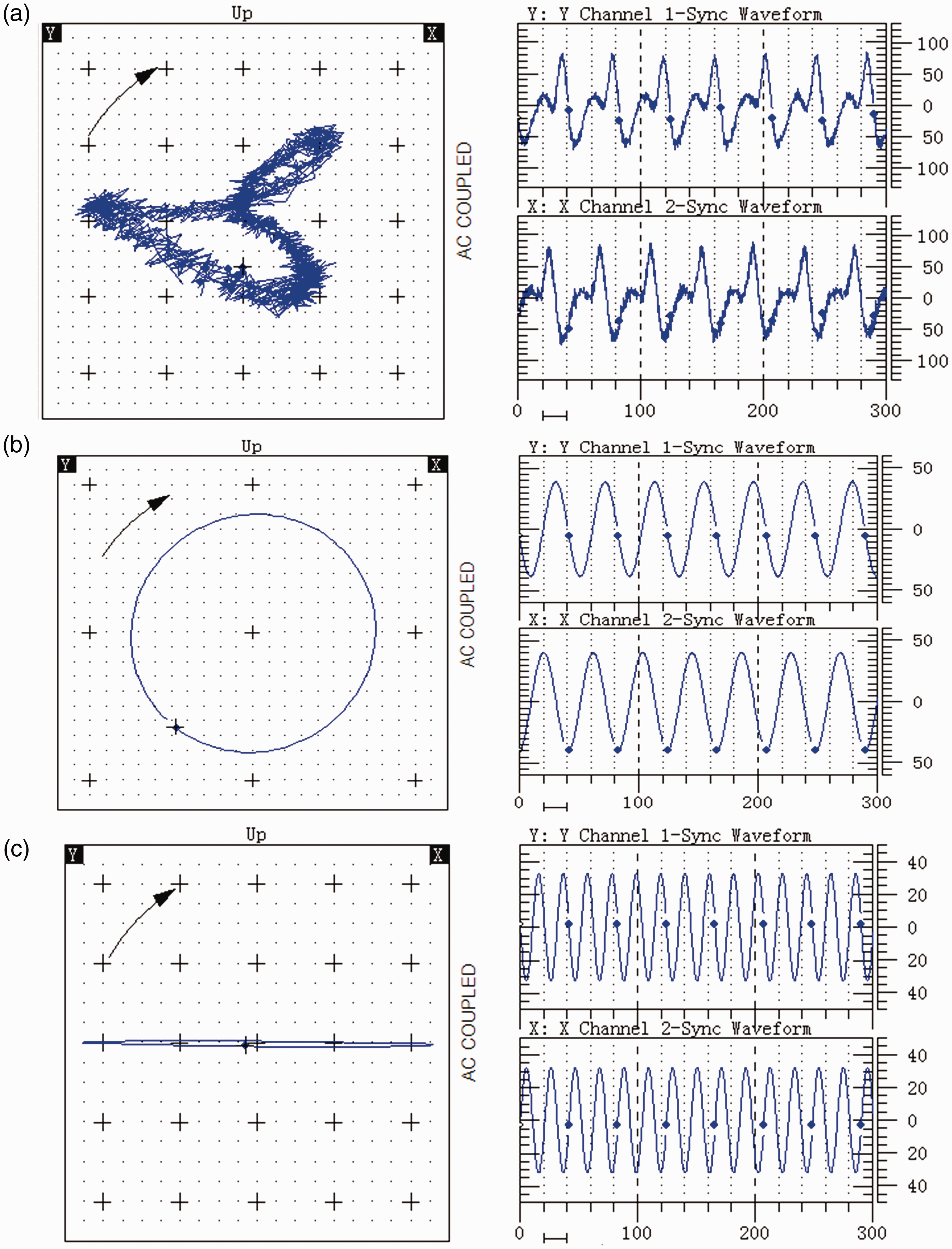
Time-domain diagram of the axis orbit. (a) Original rotor axis orbit, (b) rotor axis orbit of 1X frequency, and (c) rotor axis orbit of 2X frequency.
In order to obtain a clear axis orbit, the influence of the rotor vibration, whirling, and eccentricity on the axis orbit under rotor–stator interaction effect is analyzed accurately. In this paper, the original axis orbit is decomposed and purified, and the axis orbit that excludes the interference of super high order harmonic signals, such as the noise and electromagnetic, is obtained, while the main factors such as power frequency and 2X frequency are highlighted. Further analysis of the 1X frequency and the 2X frequency of axis orbit after filtering, it can be known that the profile of 1X frequency axis orbit diagram is approximately a circle and it was drawn along the counterclockwise direction which was reverse against the rotor rotation direction. As a result, it can be judged that the stiffness difference of the bearing in the different direction is very small and the influence of the bearing factor on 1X frequency could be ignored. Meanwhile, it can be also judged that counterclockwise arciform whirling motion exists in the running process of the mixed-flow pump, which means that there exists the rotating frequency vibration caused by the rotor imbalance. At the same time, it is observed that the 2X frequency of axis orbit is an ellipse with a large difference between long and short axes. It shows that the rotor installed with misalignment, which aggravates the vibration of the rotor of the mixed-flow pump. It is the same as the original axis orbit that the time-domain waveform in the two directions of the 1X frequency and the 2X frequency has a difference of 1/4 cycle, and it has good periodic distribution and the amplitude is relatively stable.
The frequency-domain distribution of the axis orbit is obtained by the data processing of the original axis orbit as shown in Figure 9. It can be observed that the power frequency of the two monitoring points of the rotor is 24.17 Hz from the rated speed of the mixed-flow pump.
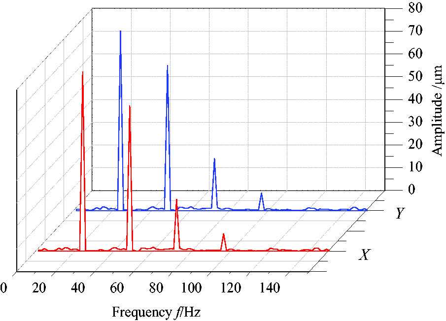
Frequency-domain diagram of axis orbit.
It can be found from the frequency distribution that the frequency distributions in the two directions are exactly the same owing to the rotating periodicity of the rotor. The vibration energy in frequency spectrogram is relatively concentrated, and the vibration energy is mainly composed of 1X frequency and 2X frequency while the triple frequency(3X frequency) and quadruplicated frequency (4X frequency) only account for a small fraction, which indicated that the rotor imbalance and the misalignment are the two major reasons causing the rotor shaft vibration. Combining the 1X frequency axis orbit diagram and its time-domain diagram, it can be found that the biggest vibration amplitude value occurs in 1X frequency during the impeller rotation. Because of the high machining accuracy in shaft system of the mixed-flow pump as well as the complement of dynamic balance test before experiment, the hydraulic imbalance becomes the most important factor that causes the shafting unbalance and the periodic hydraulic imbalance force on the impeller has a great impact on the rotor shaft vibration. Combining the 2X frequency axis orbit diagram and its time-domain diagram, it can be found that the vibration amplitude value of 2X frequency is up to 65 µm, which indicates that the misalignment problem is also a major factor affecting the shaft vibration. It can thus be seen that the shaft vibration is influenced by the rotating frequency vibration induced by the nonuniform hydrodynamic force and the 2X frequency vibration caused by the misalignment.
Effect of the rotor–stator interaction on the shaft vibration
According to the time- and frequency-domain diagrams of pressure pulsation in different position, it is found that due to the rotation of the impeller and the rotor–stator interaction between the impeller and the guide vane, periodic pressure fluctuation in the mixed-flow pump is generated. Therefore, in the process of impeller rotation, the fluctuating pressure acting on the rotor has a periodic force on the rotor shaft of the mixed-flow pump.
Considering the effect of fluid on the rotor system is mainly reflected on the impeller, so the influence of the fluctuating pressure in the impeller area on the vibration of the shaft system is mainly analyzed. At the monitoring point B, the amplitude of the pulsation appears as four peaks in a rotating cycle of the impeller, and there are one to two secondary peaks occurring simultaneously. It shows that the impeller is not only affected by the rotor–stator interaction, but also affected by the secondary flow such as leakage flow and backflow in the end wall. As a result, periodic hydrodynamic vibrations on the rotor system are generated, and the constantly changing zigzagged sharp corners appear on the original axis orbit.
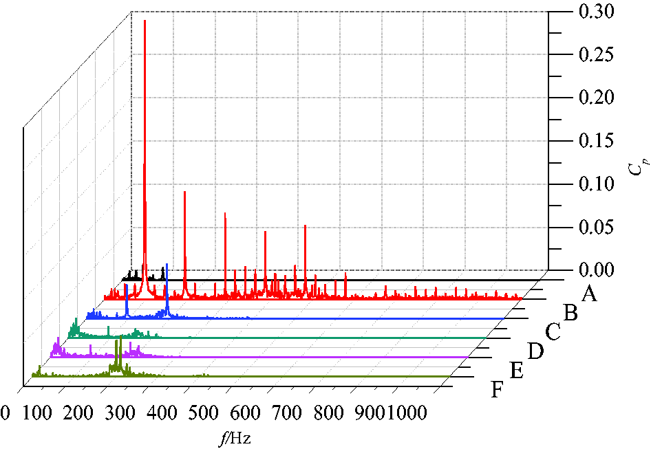
The frequency domain of pressure fluctuation and axis orbit is shown in Figure 10. Comparing the frequency domain of axis orbit and pressure fluctuation, it is found that the hydraulic imbalances under the rotating frequency of the impeller have great influence on the vibration of the shaft system, that is the hydraulic imbalance has a great influence on the 1X frequency and 2X frequency of the axis orbit, while the rotor–stator interaction effect induced by the blade passing frequency takes the second place on the vibration of the shafting, which is the main factor inducing the 4X frequency vibration of the axis orbit.
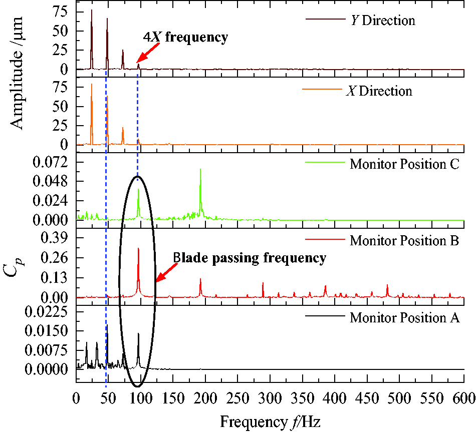
Frequency-domain diagram of pressure fluctuation and axis orbit.
Conclusions
The analysis of time domain and frequency domain of pressure pulsation shows that the impeller rotation is the main factor for causing the pressure pulsation, and the pulsation frequency is Z times the rotation frequency or its harmonic frequency. The pressure pulsation of each point in the impeller passage is sine curve and presents the periodic characteristic. In the middle of the tip of the blade, the coupling of pressure pulsation is strong, the amplitude of pulsation is the largest, and the rotor–stator interaction is most obvious. Along the direction of the main stream, the velocity energy is converted into pressure energy, the rotor–stator interaction effect is gradually reduced, and the impeller rotation frequency becomes the main frequency of the pressure pulsation.
Due to the influence of hydraulic exciting vibration and noise, high harmonic signal exists in the original axis orbit signal and there are many zigzag sharp corners in the axis orbit diagram. At the same time, there are secondary peaks in the time-domain waveform diagram, which shows the existence of the hydraulic imbalance in rotor or the misalignment of the rotor. 1X frequency of the axis orbit is an ellipse with little difference between long and short axes and 2X frequency of the axis orbit is an ellipse with large difference between long and short axes. It can be judged that there is whirling vortex like arch in the rotor and the existence of rotor which is creating misalignment phenomenon.
Based on the time- and frequency-domain diagram of the pressure fluctuation, it is shown that the pressure pulsation caused by the rotation of the impeller generates periodic force on the rotor shaft of the mixed-flow pump, and the constantly changing zigzagged sharp corner appears on the original axis orbit. The hydraulic imbalance under the impeller rotating frequency has a great influence on the vibration of the shafting, while the rotor–stator interaction effect induced by the blade passing frequency takes the second place on the vibration of the shafting, which is the main factor inducing the 4X frequency vibration of the axis orbit.
Footnotes
Author's note
Wei Li is also affiliated with Institute of Fluid Engineering Equipment, JITRI, Zhenjiang 202013, China.
Declaration of conflicting interests
The author(s) declared no potential conflicts of interest with respect to the research, authorship, and/or publication of this article.
Funding
The author(s) disclosed receipt of the following financial support for the research, authorship, and/or publication of this article: The work was sponsored by the National Natural Science Foundation of China (No. 51679111, No. 51579118, and No. 51409127), National Key R&D Program Project (No. 2017YFC0403703), PAPD, Six Talents Peak Project of Jiangsu Province (No. HYZB-002), Key R&D Program Project in Jiangsu Province (BE2016319, BE2017126), Natural Science Foundation of Jiangsu Province (No. BK20161472), Science and Technology Support Program of Changzhou (No. CE20162004), Key R&D Program Project of Zhenjiang (No. SH2017049), and Scientific Research Start Foundation Project of Jiangsu University (No. 13JDG105).