
Abstract
In this paper, the nonlinear response characteristics of a single degree of freedom lumped mass model with a new support looseness fault are analyzed. In this model, a new nonlinear contact stiffness model between the support and foundation is considered, which considers the elastic–plastic deformation of the contact parts. The nonlinear response of the system is obtained by numerical integration methods. The nonlinear results are compared with an asymmetric model and a piece-wise contact model. By comparing three different looseness fault models, the mechanism of generating multi-frequencies and fractional frequencies is analyzed. The result shows that plastic deformation makes the displacement amplitude increase rapidly; odd harmonics appear in symmetric stiffness model due to the modulation of symmetric shock forces; however, harmonic response appears in asymmetric stiffness model; when the contact number is odd, the frequency components contain odd or even order fractional frequencies at supercritical speeds due to the incompatibility of contacts on the upper and lower surfaces; when the contact number is even, multiple frequency components appear at subcritical frequencies.
Keywords
Introduction
Looseness fault is a common fault which exists in rotor system. It is caused by the different contact nonlinear stiffness, so it is difficult to measure the deformation of the contact parts. Also it is difficult to establish a looseness fault model considering the contact deformation and explain the relation between contact numbers and fractional and multiple frequency components. In order to understand the essence of looseness fault better, establishing an effective contact stiffness model and analyzing nonlinear response characteristics are of great significance.
Many scholars have studied the looseness fault based on lumped mass model. Ehrich 1 and Wang et al.2,3 used a simple numerical model of a rotor employing a piece-wise linear (i.e. a bilinear) bearing support stiffness to represent the system; it was possible to replicate the new class of asynchronous rotor dynamic response in high-speed rotors over a range of sub-, trans-, and supercritical high-speed rotor operation. Muszynska and Goldman 4 established a rotor–bearing–stator model with a one-lateral-mode unbalanced, bearing looseness and rotor–stator rubbing, showing the nonlinear characteristics of the periodic vibrations of synchronous (1×), sub-synchronous (1/2×, 1/3×…), and multiples (2×, 3×…). Goldman and Muszynska 5 developed an analytical algorithm for investigating local nonlinear effects in rotor systems. They used a specially developed variable transformation that smoothes discontinuities, and then they applied an averaging technique. Their results showed good agreement with experimentally observed typical behaviors and orbits of rubbing rotors. In the last two papers, the effects of pedestal looseness on the system response were also studied. Lu et al. 6 analyzed the stability of reduced rotor pedestal looseness fault model. In all the previous studies, experiments, nonlinear dynamics analysis and characteristics analysis based on lumped mass model with looseness fault are performed gradually. Recently, he also studied polynomial dimensional decomposition (PDD) and the Monte Carlo simulation. PDD can describe the amplitude–frequency characteristics with random variables except the frequency around the resonant frequency.7,8
In recent years, the finite element method (FEM) has been used to establish looseness fault model by many scholars. Ma et al. 9 studied the nonlinear vibration characteristics of a rotor system with pedestal looseness fault under different loading conditions. In recent papers, Ma et al. 10 studied the rubbing rotor system with pedestal looseness fault and analyzed the steady-state vibration based on the FEM. Ma et al. 11 also established a finite element model of a rotor system with pedestal looseness stemming from a loosened bolt and analyzed the effects of the looseness parameters on its dynamic characteristics. Qin et al. 12 investigated three-dimensional nonlinear finite element models with bolt loosening. The time-varying joint stiffness resulting from the bolt looseness and its influence on steady-state response was calculated. Wang and Chen 13 established a rotor-support-casing whole model with looseness fault for certain type of turbofan aero-engine. The casing acceleration response characteristics were analyzed. However, the nonlinear elastic–plastic contact between support and foundation is not considered in looseness fault. Liu et al. 14 established finite element model of dual-disk rotor system with looseness-rubbing fault and analyzed the dynamic characteristics of the health rotor system.
Some scholars have established contact mechanic models. Jackson and Green 15 used several measured profiles of real surfaces having vastly different roughness characteristics to predict contact areas and forces from various elastic contact models and contract them to a deterministic fast Fourier transform-based contact model. Wang et al. 16 analyzed elastic–plastic contacts by means of a three-dimensional numerical model based on minimization of complementary energy. Results were compared to those from FEM. Zhang et al. 17 established a theoretical model that predicts the interfacial contact stiffness of fractal rough surfaces by considering the effects of elastic and plastic deformation of fractal asperities. Excellent agreement is observed between the contact stiffness predicted by theoretical model and by experimental results. Xu and Wang 18 established analytical model for elastic–plastic contact in normal direction of rough surfaces. The proposed model can model the contact behavior of the rough surface and agrees well with the finite element-based surface contact model. Also, Xu et al. 19 proposed a new interface contact mechanical model considering tangential micro-slip friction and variable normal load simultaneously, which can be used to simulate contact interface mechanical behavior more correctly and perfectly. Li et al. 20 established a real area of contact, contact load area, and contact stiffness model based on statistical method. However, these contact models are not applied to rotor system and nonlinear response characteristics were not studied deeply.
At present, many models were established with support looseness fault using piece-wise nonlinear stiffness; however, the nonlinear elastic–plastic contact between support and foundation is considered. Plastic contact is neglected in many research papers. Actually plastic contact exists when rotor system has looseness fault. Based on this, some nonlinear characteristics are investigated. In this paper, lumped mass model with looseness fault considering elastic–plastic contact is established; the nonlinear vibration response characteristics are discussed by numerical integration methods. Also multiple frequency and fractional order frequency components are common in the rotor dynamics with looseness fault. However, less research is related to the frequency components of the contact number. Frequency generation mechanism is discussed in this paper.
New support–foundation looseness fault modeling
Figure 1 is the bolt joint sketch diagram. As shown in Figure 1, bolt is used to connect foundation and support. The contact surface is formed by pressing the bolt. When the support is vibrating with a rotor system, the joint surface is deformed in different area.
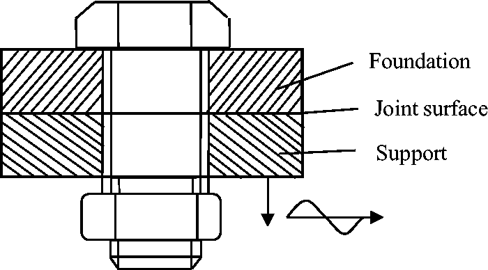
Bolt joint sketch diagram.
In previous research, most contact stiffness models are piece-wise, as shown in Figure 2, where F is the contact force and Δy is the relative displacement. The contact between support and foundation is assumed to be elastic contact. However, elastic–plastic contact is not considered in all these models.
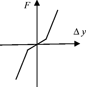
Piece-wise stiffness model.
Figures 3 and 4 are pressure distribution of contact surface at elastic stage and elastic–plastic stage, where F is the contact force and Δy is the relative displacement. When the relative displacement of support and foundation is small, the elastic contact exists; otherwise, when the relative displacement of foundation and support is larger, the elastic and plastic contact appears.
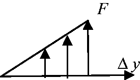
Force distribution at elastic stage.
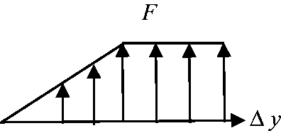
Force distribution at elastic–plastic stage.
A single degree of freedom lumped mass model with looseness fault
A single degree of freedom lumped mass model
In order to simulate the rotor dynamic behavior when the nonlinear contact appears, a single degree of freedom lumped mass model is established; the differential equations of the unbalance response of a single disk mounted on a massless shaft can be described as follows

An elastic–plastic looseness fault model
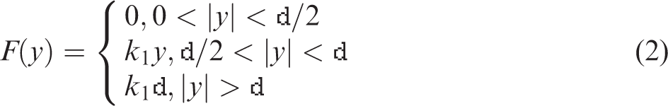
In order to simulate the elastic–plastic contact behavior, a contact function is established, which can be described as follows
A conventional piece-wise looseness fault model
In order to compare the differences between the elastic–plastic model and conventional model, a piece-wise looseness fault model is established, which can be expressed as follows
Simulation analysis of looseness fault characteristics
For studying the elastic–plastic contact models and comparing with the results of the piece-wise model in a single freedom of lumped mass model, some parameters are set to obtain the nonlinear vibration.
It is assumed that the mass of the support m = 10 kg, the vibration eccentricity of the rotor system e = 1 µm, the damping between the support and the foundation c = 300 N s/m, the line stiffness k = 1 × 10⁵ N/m, the contact stiffness between the support and foundation k1 = 5 × 10⁶ N/m, and the clearance δ = 5 × 10⁻⁶ m.
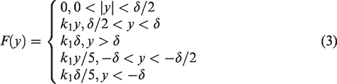
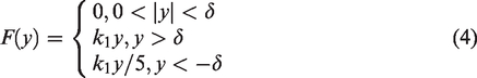
The improved Newmark-β algorithm 21 is used to solve the contact model. In equation (2), if the support is not contacted, the contact condition is set as 0; if the support contacts the foundation in an elastic stage, the contact condition is set as 1; and if the support contacts the foundation in a plastic stage, the contact condition is set as 2. In equation (3), if the support is not contacted, the contact condition is set as 0; if the support contacts the upper and lower surface of foundation in an elastic stage, the contact conditions are set as 1 and −1; and if the support contacts the upper and lower foundation in a plastic stage, the contact conditions are set as 2 and −2. In equation (4), if the support is not contacted, the contact condition is set as 0; if the support contacts the upper surface, the contact condition is set as 1; and if the support contacts the lower surface, the contact condition is set as −1.
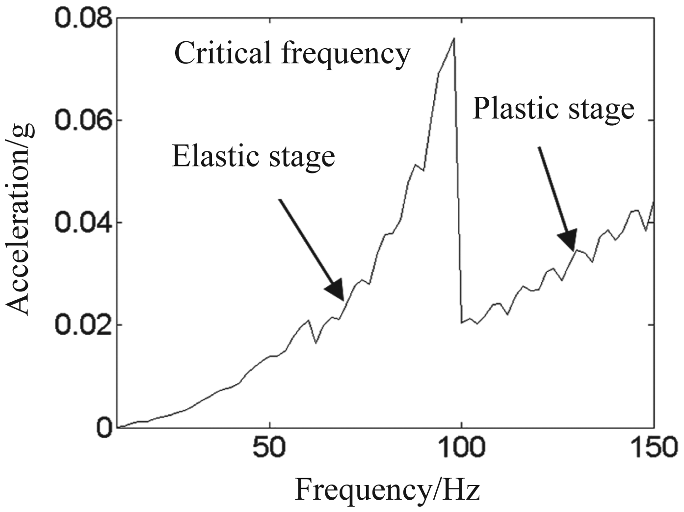
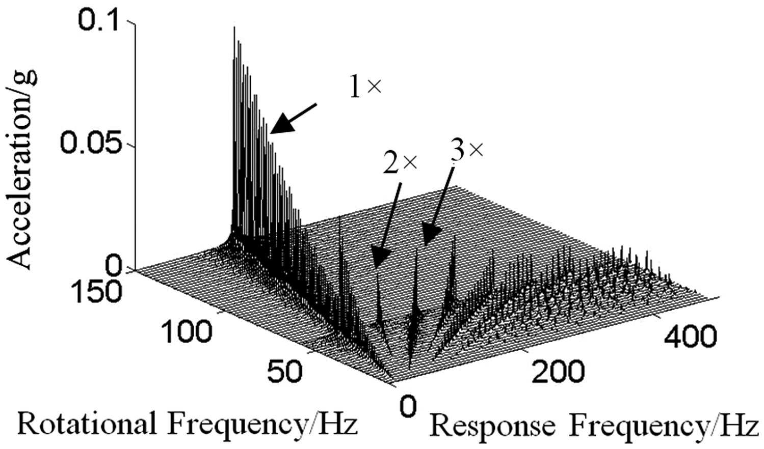
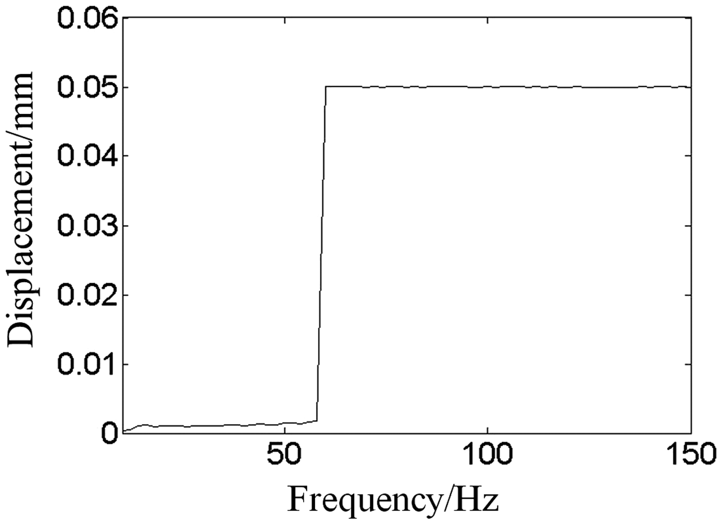
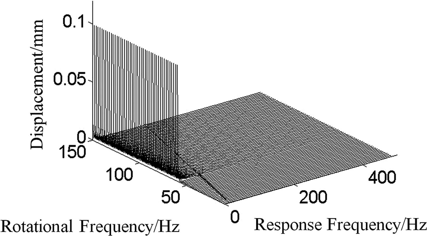
Figures 5 to 8 are Bode plot and waterfall plot of acceleration and displacement of model 1. In Figures 5 and 7, when the frequency is 100 Hz, there is a rapid decrease in 1× acceleration and a rapid increase in displacement amplitude. The amplitude of acceleration keeps increasing stably at plastic stage after 100 Hz and the amplitude of displacement is constant at plastic stage after 100 Hz. Figure 6 shows that odd harmonics of acceleration appear during an elastic stage and 1× appears at a plastic stage; Figure 8 shows only 1× appears at an elastic stage and only 0 Hz appears at a plastic stage and the rotor system is in static plastic deformation.
Bode plot of 1× acceleration.
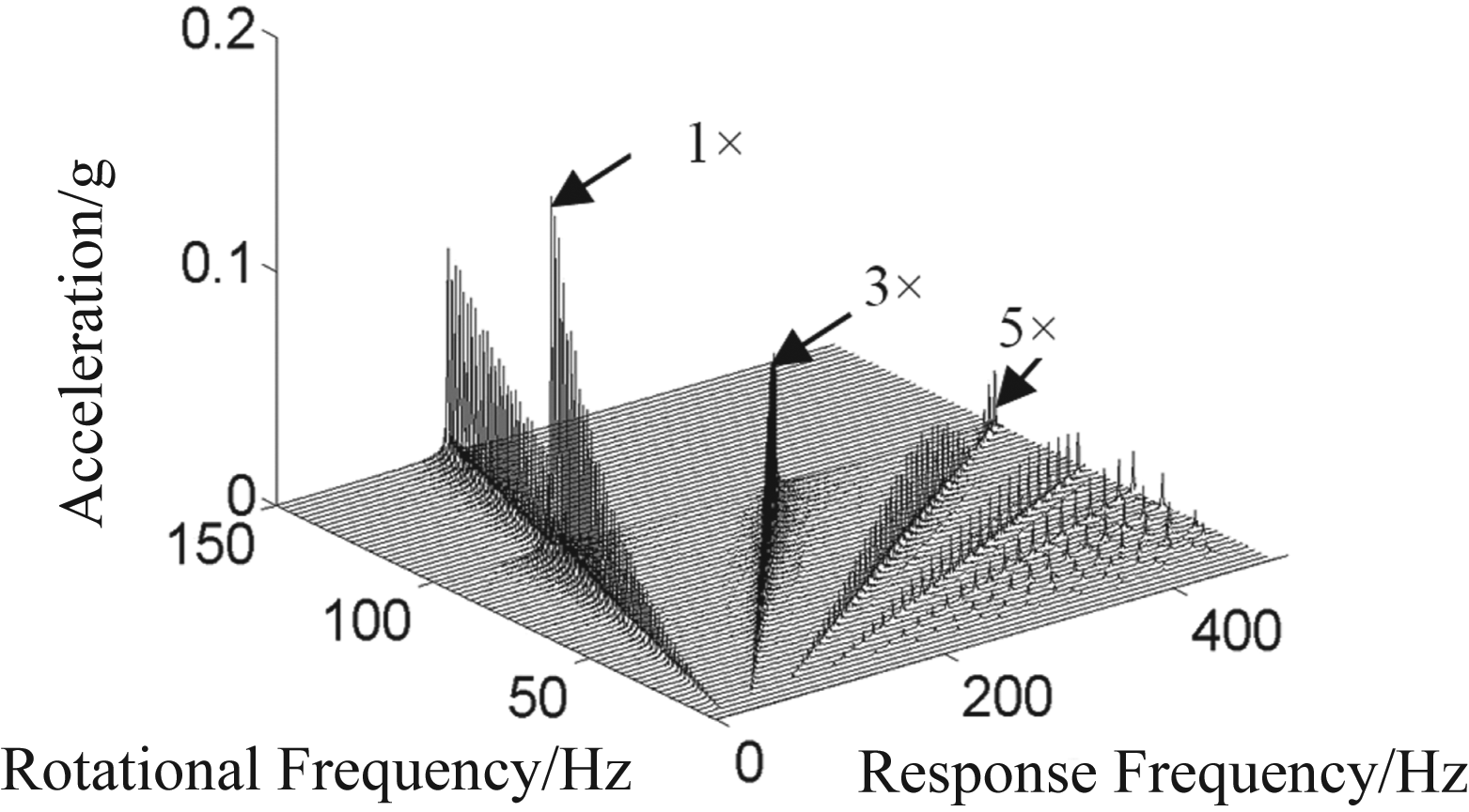
Waterfall plot of acceleration.
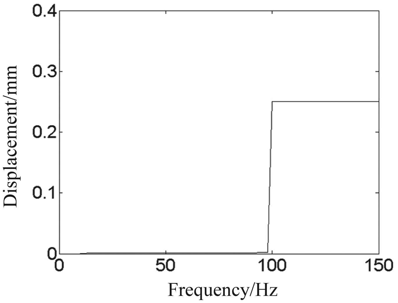
Bode plot of displacement.
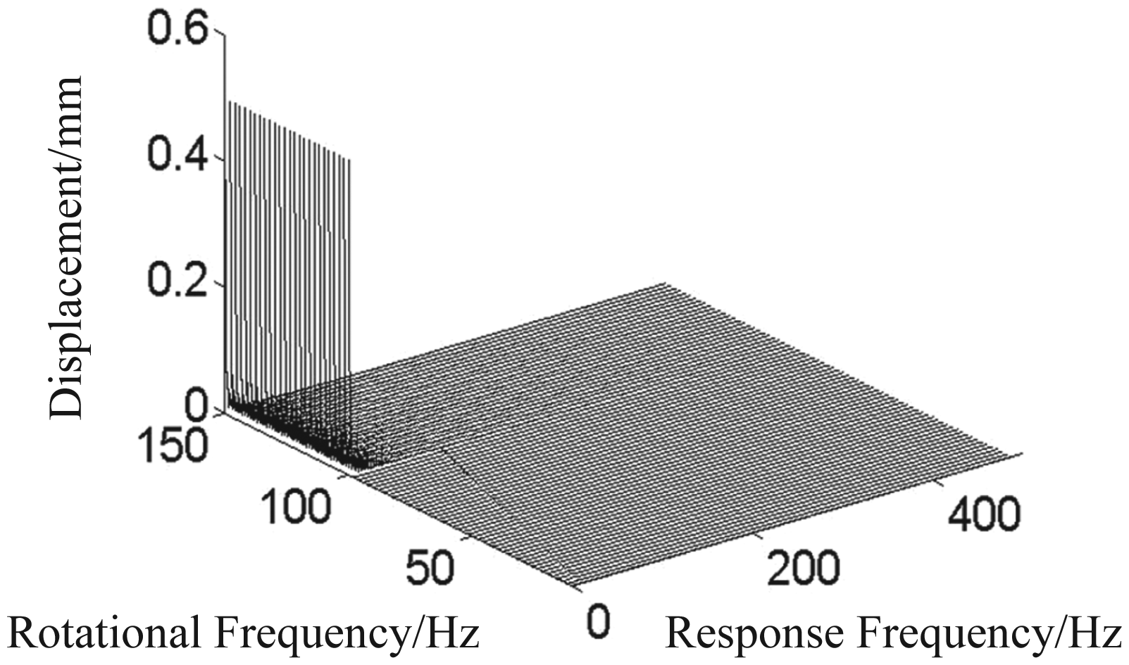
Waterfall plot of displacement.
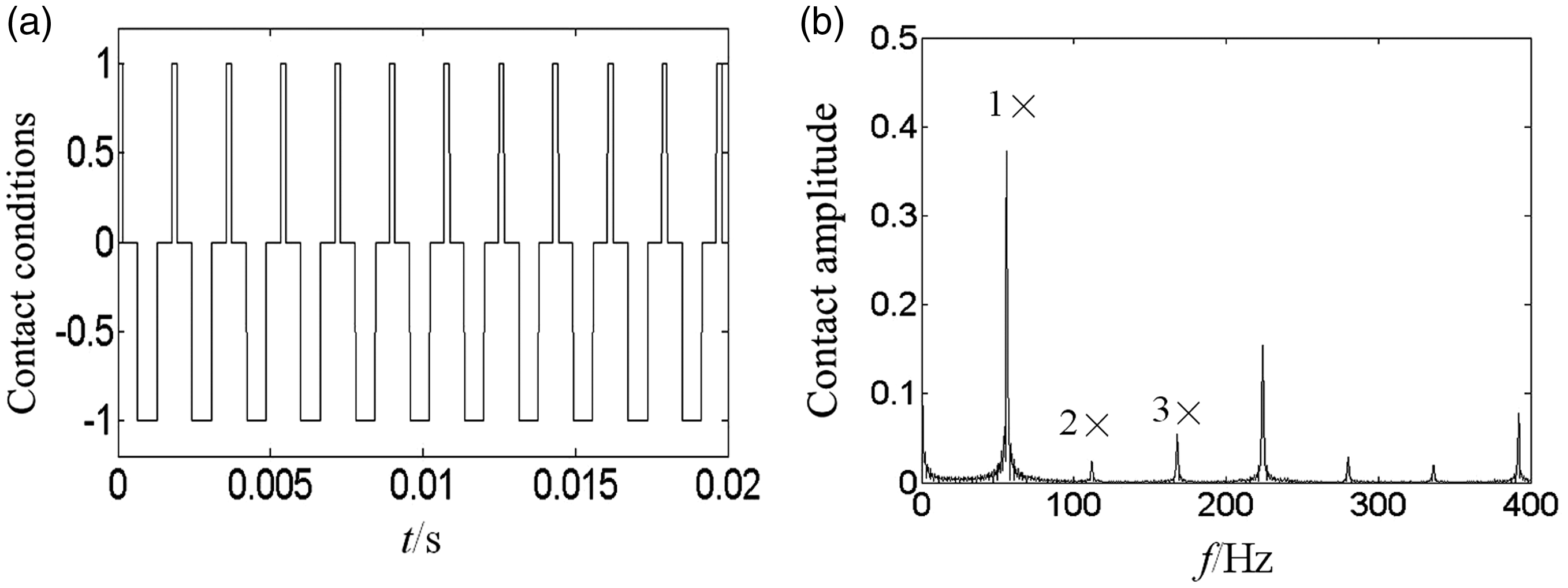
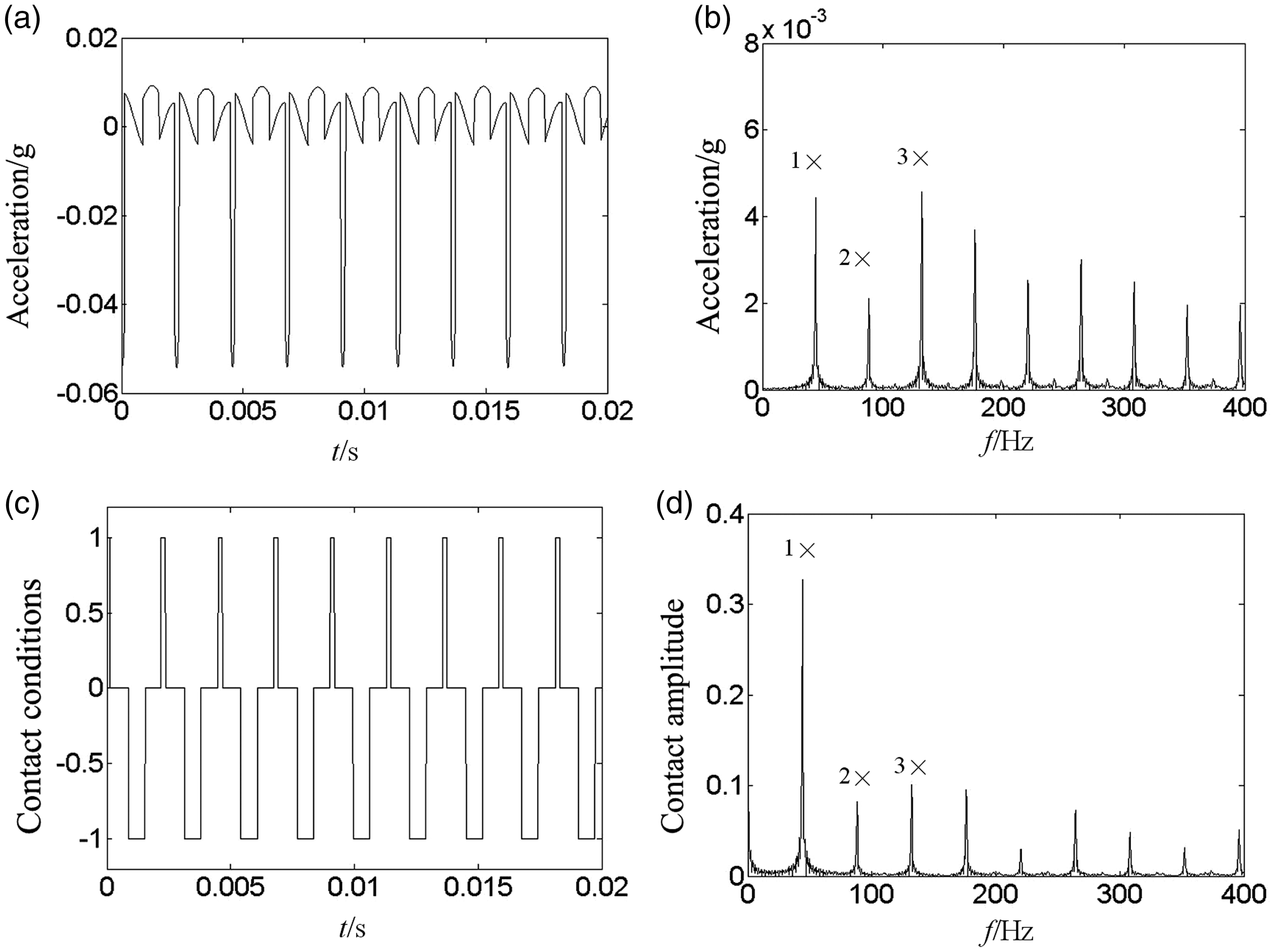
Figures 9 to 12 are displacement, acceleration, and contact condition wave and spectrums at 14, 48, 98, and 118 Hz. Figure 9 shows the acceleration and contact wave at lower vibrating frequency 14 Hz at the elastic contact stage. With the increase of exciting frequency to 48 Hz, the acceleration wave is shocked up and down symmetrically and odd harmonics appear. It shows that there are two components of frequency, which includes the rotational frequency excited by the unbalance force and the shock frequency excited by stiffness periodic changing. As shown in Figure 10(d), which shows the contact force frequencies, the stiffness changing frequency is 2×, which means the support will contact the upper and lower surface of the foundation once in one rotational period. It is found that the frequency is modulated by the symmetric shock force. The side-band frequency of acceleration is 2×, as shown in Figure 10(b). Figure 11 shows similar phenomenon. Figure 12 shows displacement, acceleration, and the contact conditions at higher frequency 118 Hz at plastic stage. Figure 12(a) shows a large plastic deformation 0.25 mm. Figure 12(b) is the spectrum of displacement, which shows higher amplitude at 0 Hz and the system is under static plastic stage. Figure 12(c) and (d) shows 1× harmonic component of acceleration appears at plastic stage.
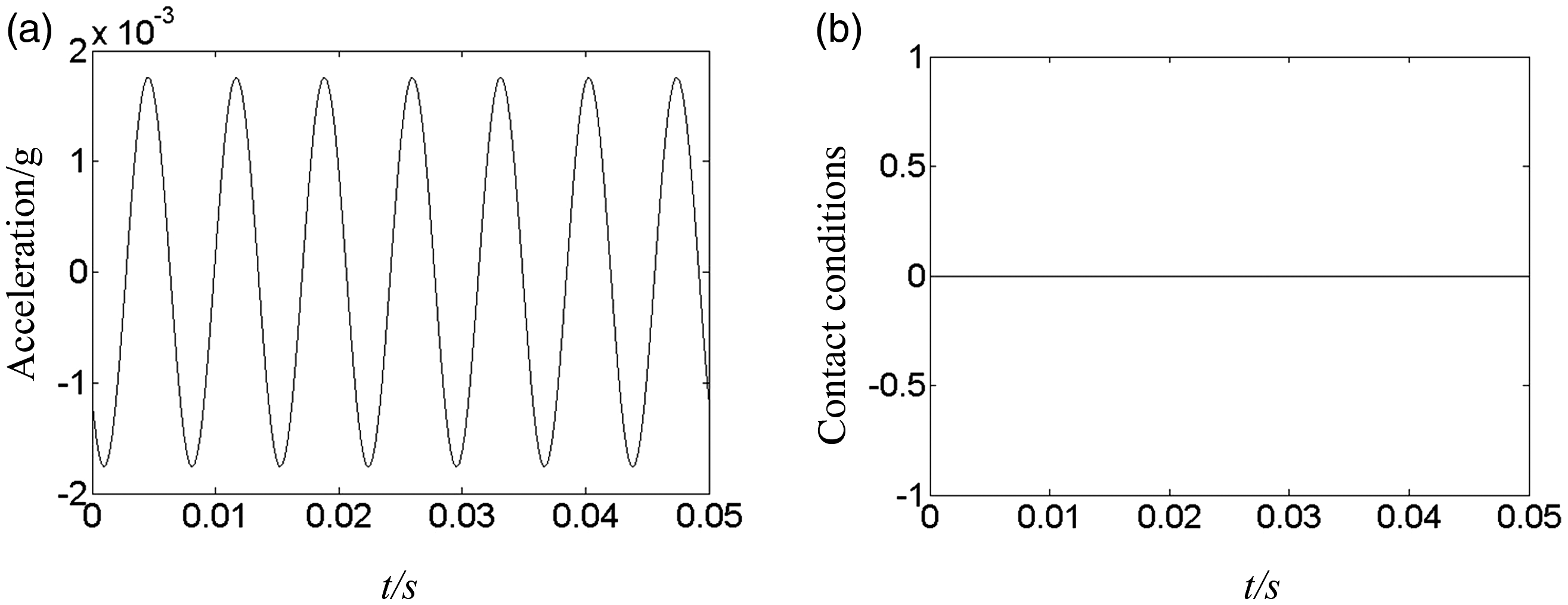
Acceleration wave and contact conditions at 14 Hz. (a) Acceleration wave and (b) contact conditions.
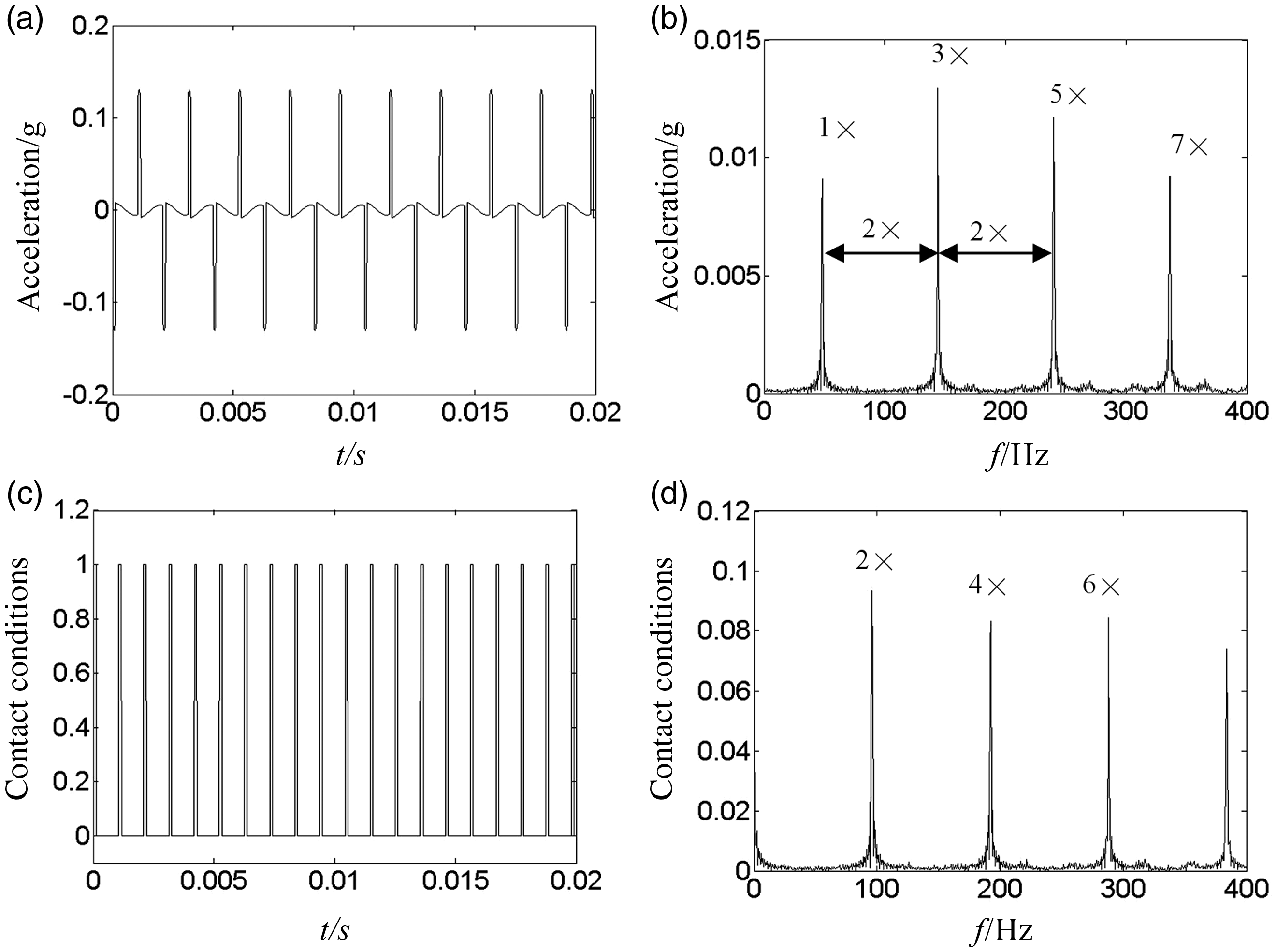
Acceleration wave, contact conditions, and their spectrums at 48 Hz. (a) Acceleration wave, (b) acceleration spectrum, (c) contact conditions, and (d) contact spectrum.
Acceleration wave, contact conditions, and their spectrums at 98 Hz. (a) Acceleration wave, (b) acceleration spectrum, (c) contact conditions, and (d) contact spectrum.
Acceleration wave, contact conditions, and their spectrums at 118 Hz. (a) Displacement wave, (b) displacement spectrum, (c) acceleration wave, and (d) contact conditions.
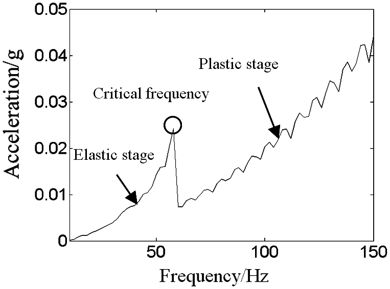
For comparing the results with symmetric and asymmetric stiffness of elastic–plastic model, numerical simulation is used to obtain response characteristics from equation (3). Because the stiffness at the lower surface is reduced to one-fifth the stiffness at the upper surface, it is easier to get access to plastic stage. The critical frequency has been changed from 100 to 58 Hz, as shown in Figure 13. Figure 14 is the waterfall of acceleration, which shows odd and even harmonic components, being different to the odd harmonic components in Figure 6. Because the changing stiffness in upper and lower surface is same in equation (2), two converse shocks appear in one period; however, due to the difference of stiffness in upper and lower surface, the interval of two shocks is asynchronous, so odd and even harmonics appear in acceleration spectrum.
Bode plot of 1× acceleration.
Waterfall plot of acceleration.
Figures 15 and 16 are Bode plot and waterfall plot of displacement from model 2. In Figures 13 and 15, when the frequency is 58 Hz, there is a rapid decrease in acceleration and a rapid increase in displacement amplitude. The amplitude of acceleration keeps increasing stably at plastic stage after 58 Hz and the amplitude of displacement is constant at plastic stage after 58 Hz. Figure 16 shows only 1× appears at elastic stage and only 0 Hz appears at plastic stage and the rotor system is in static plastic deformation stage.
Bode plot of displacement.
Waterfall plot of displacement.
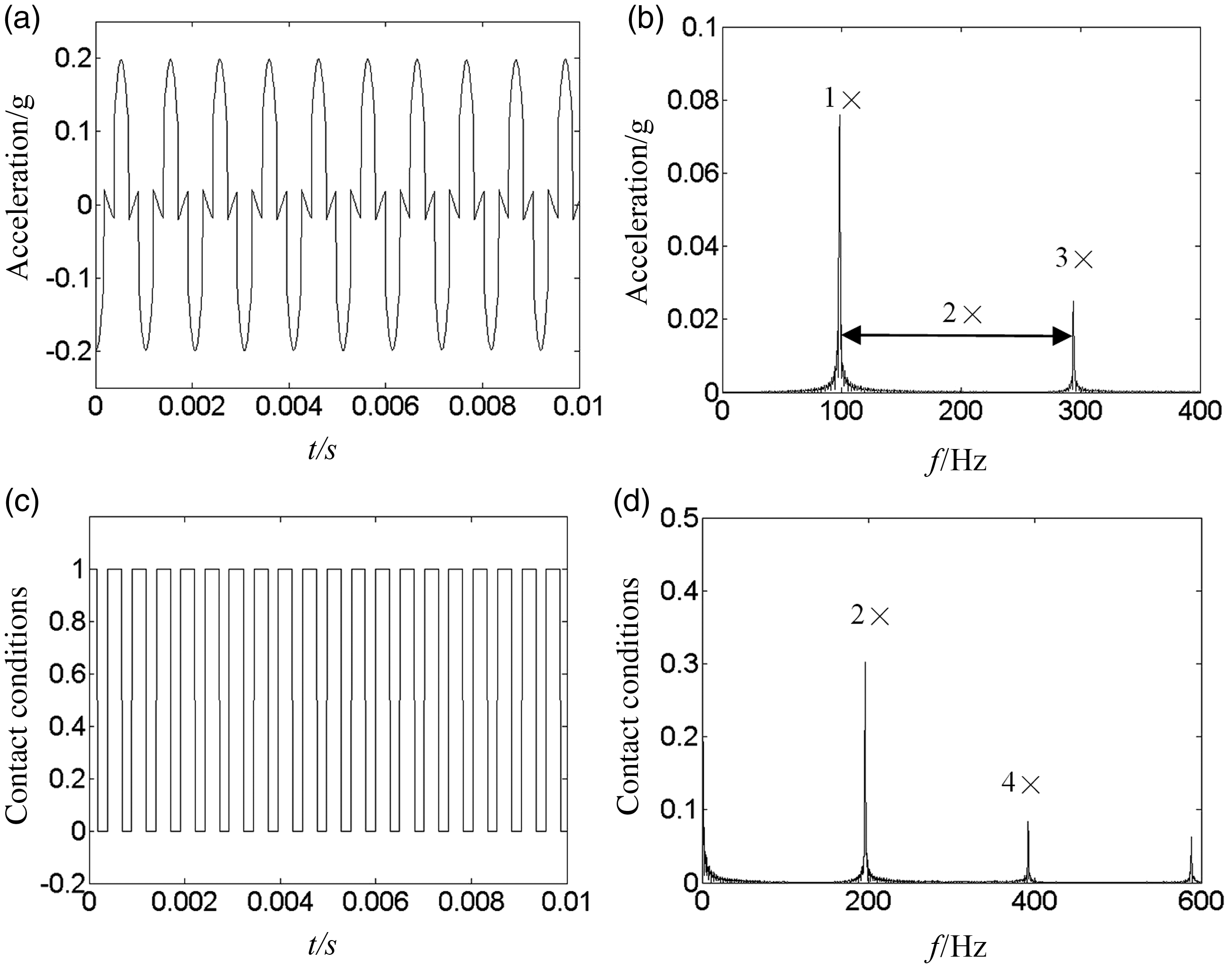
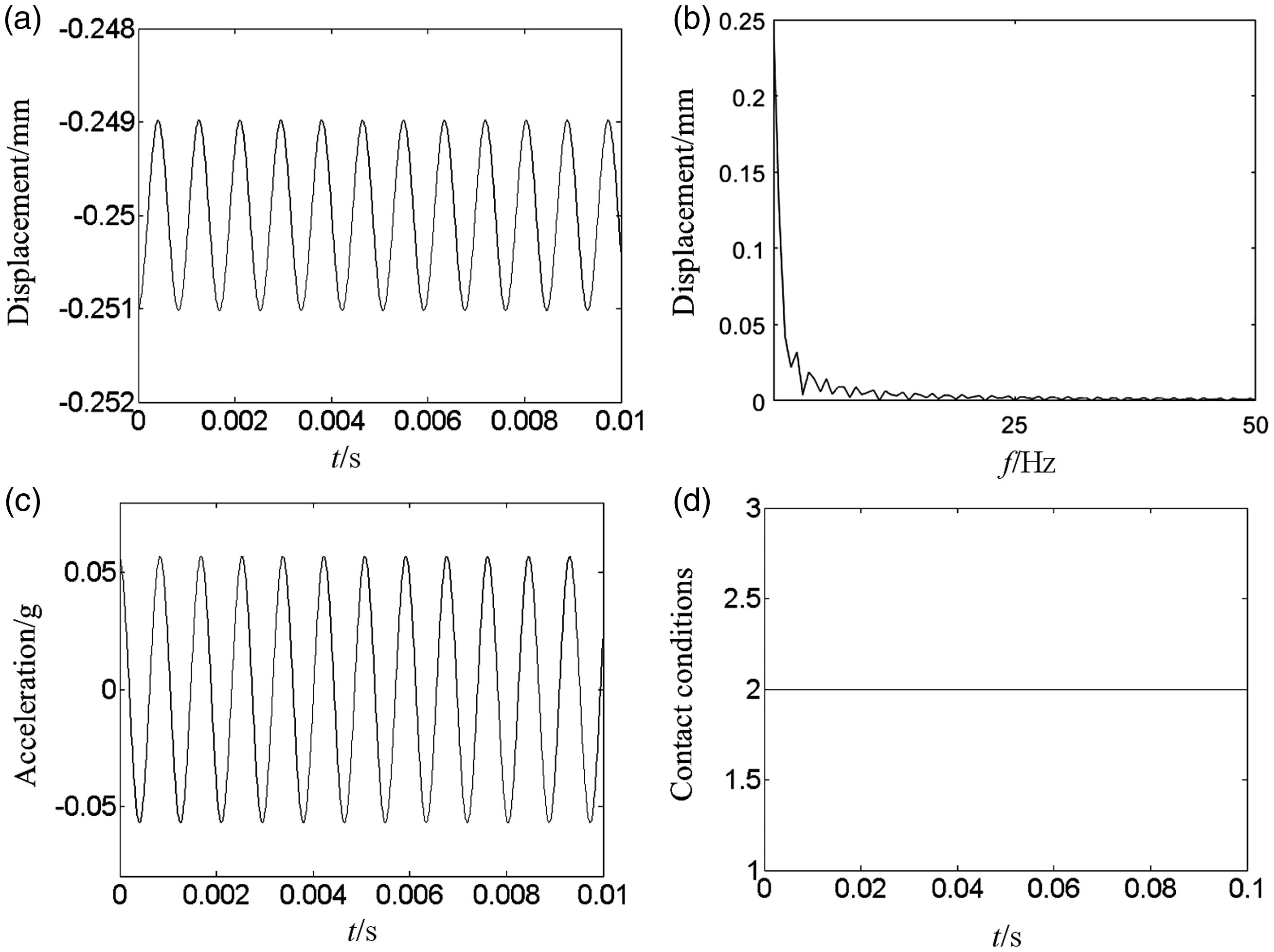
Figures 17 and 18 are displacement, acceleration, and contact conditions wave and spectrums at 56 and 80 Hz. Figure 17 shows the elastic contact stage at lower frequency 56 Hz. The acceleration wave shocks up and down asymmetrically and its frequency components are odd and even order harmonics. It shows that there are two components in frequency spectrum, which includes the rotational frequency excited by the unbalance force and the shock frequency excited by asymmetric stiffness periodic changing. As shown in Figure 17(b), the contact conditions’ frequencies show the stiffness changing frequencies are harmonic components, which means the support will contact the upper and lower surface of the support once in one rotating period but two different periodic shock signals are convoluted with unbalanced force so the frequency components of acceleration response are multi-frequencies. Figure 18 shows the plastic stage at higher frequency 80 Hz. Figure 18(a) is the displacement of the support, showing a large plastic deformation of 0.05 mm. Figure 18(b) shows the contact condition is at plastic stage.
Contact conditions, and their spectrums at 56 Hz. (a) Contact conditions and (b) contact spectrum.
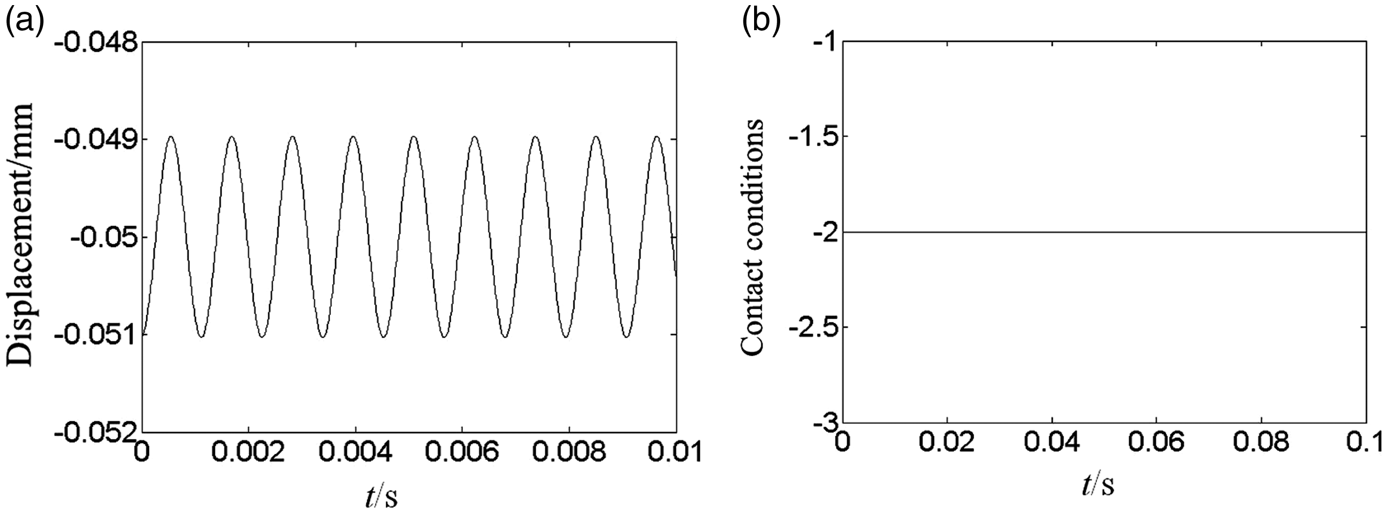
Displacement wave and contact conditions at 80 Hz. (a) Displacement wave and (b) contact conditions.
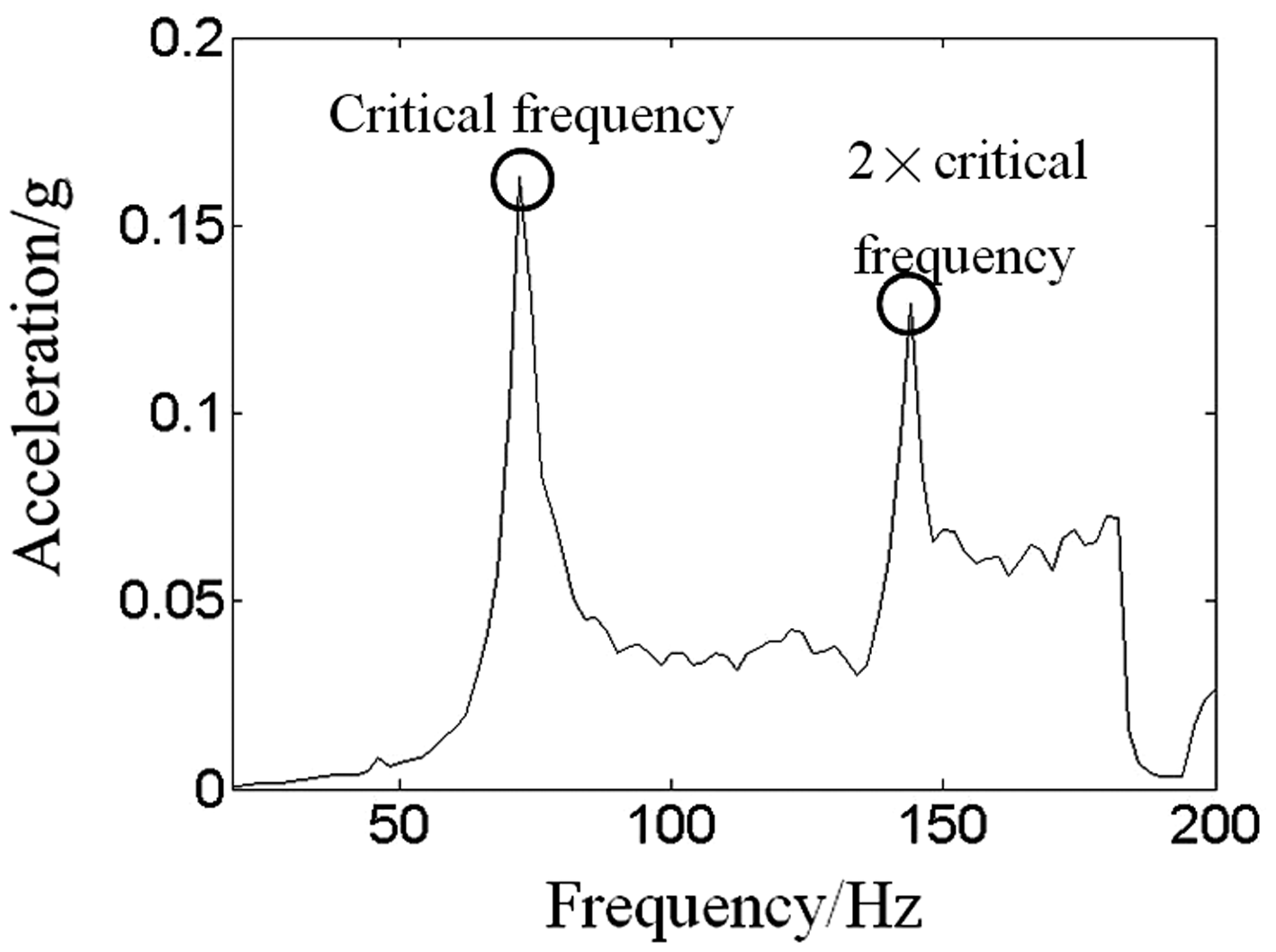
Figures 19 and 20 are Bode plot and waterfall plot of 1× acceleration from equation (4). In Figure 19, the amplitude is peak at 72 and 144 Hz which is two times the critical frequency. Figure 20 shows that super-harmonic and sub-harmonic components appear which is caused by the asymmetric stiffness changing and the frequency-lock characteristics.
Bode plot of 1× acceleration.
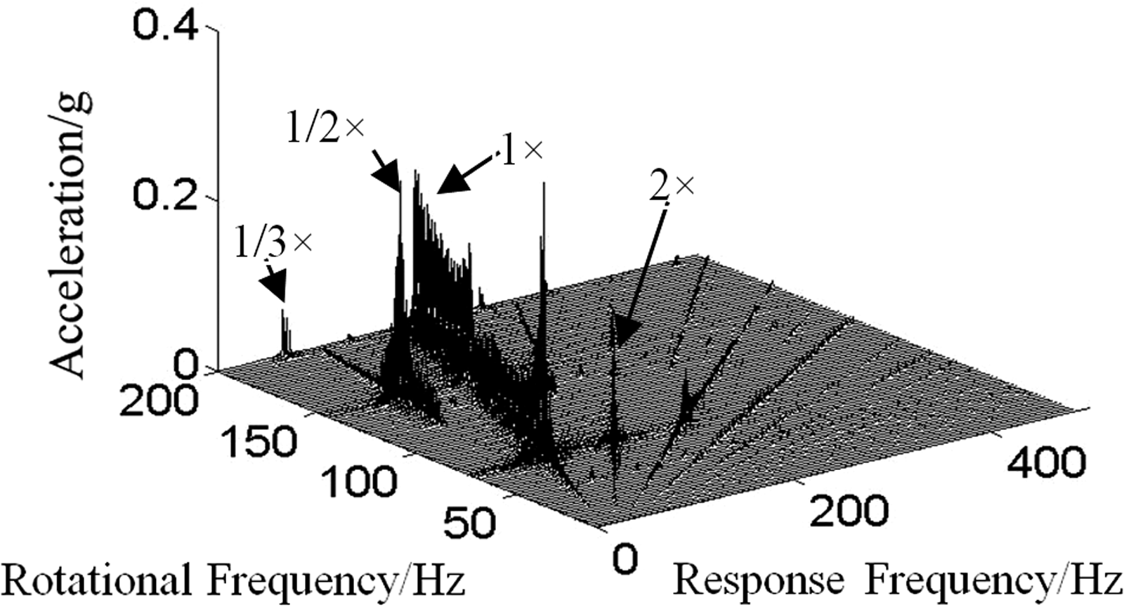
Waterfall plot of acceleration.
Figures 21 to 25 are acceleration and contact conditions wave and their spectrums at 20, 44, 124, 130, and 200 Hz. Figures 21(a) and 22(a) show two different intensive shocks in one rotational period. The larger the stiffness of the contact surface, the larger the recovery force and the less time of contact time. Figures 21(b) and 22(b) show multi-frequencies components, which are caused by unbalance force and two different periodic shocks, as shown in Figures 21(d) and 22(d).
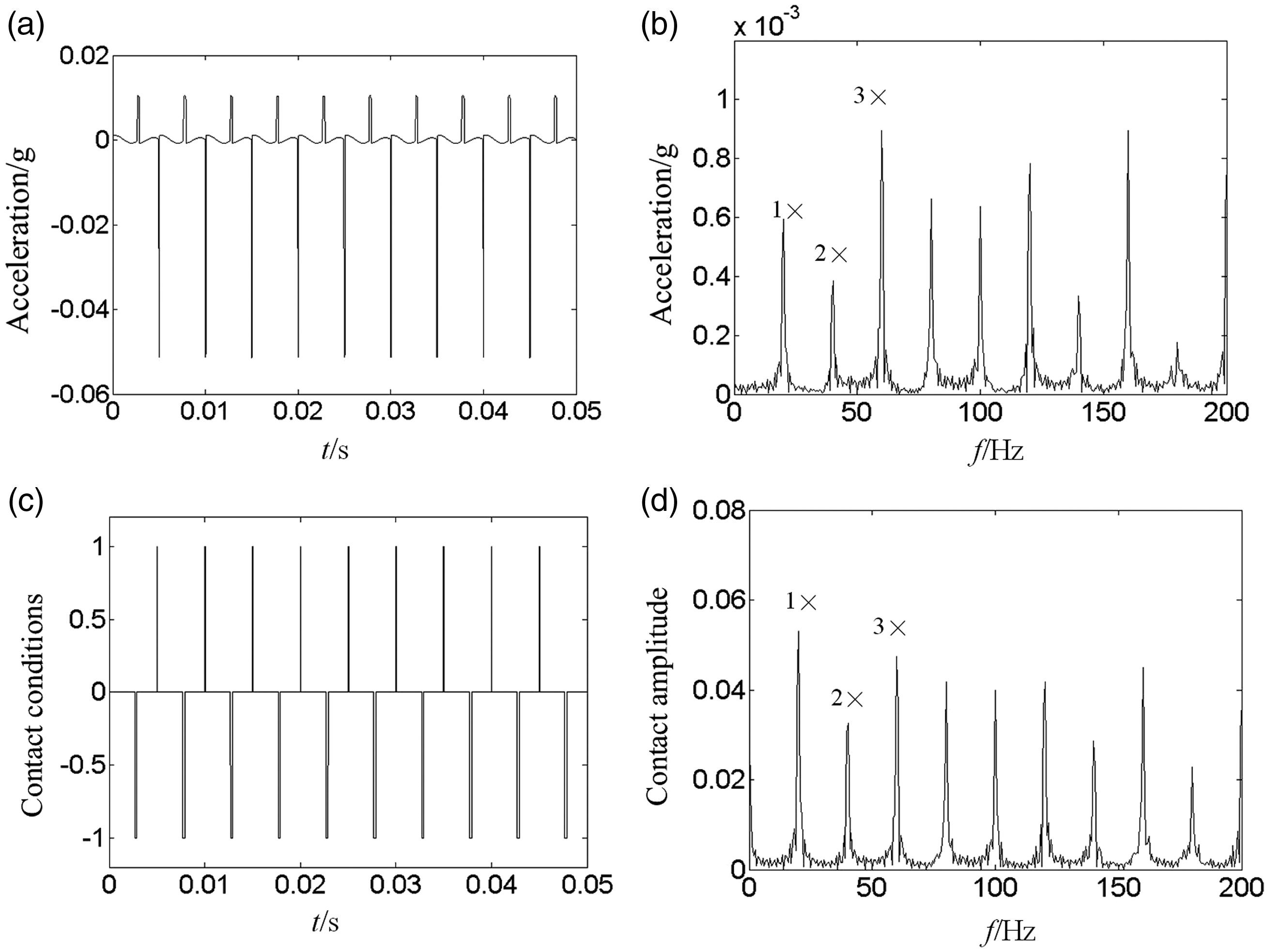
Acceleration wave, contact conditions, and their spectrums at 20 Hz. (a) Acceleration wave, (b) acceleration spectrum, (c) contact conditions, and (d) contact spectrum.
Acceleration wave, contact conditions, and their spectrums at 44 Hz. (a) Acceleration wave, (b) acceleration spectrum, (c) contact conditions, and (d) contact spectrum.
Figures 23(a) and 24(a) show three different and five intensive shocks in one oscillating period. Also Figure 23(a) appears that contact numbers of upper surface and lower surface are two and one, and Figure 24(a) appears that contact numbers of upper surface and lower surface are three and two. There are two successive contacts on one surface. The larger the stiffness of the contact surfaces, the larger the recovery force and the less time of contact time. Figure 23(b) and (d) shows fractional frequencies, such as 1/2×, 3/2× and 1/4×, 1/2×, 3/4×, 5/4×, which are caused by unbalance force and different odd periodic shocks.
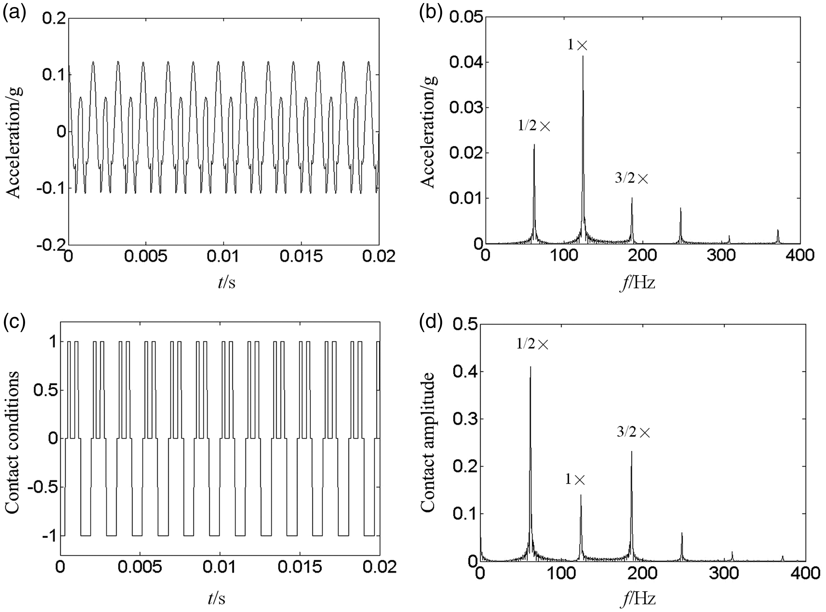
Acceleration wave, contact conditions, and their spectrums at 124 Hz. (a) Acceleration wave, (b) acceleration spectrum, (c) contact conditions, and (d) contact spectrum.
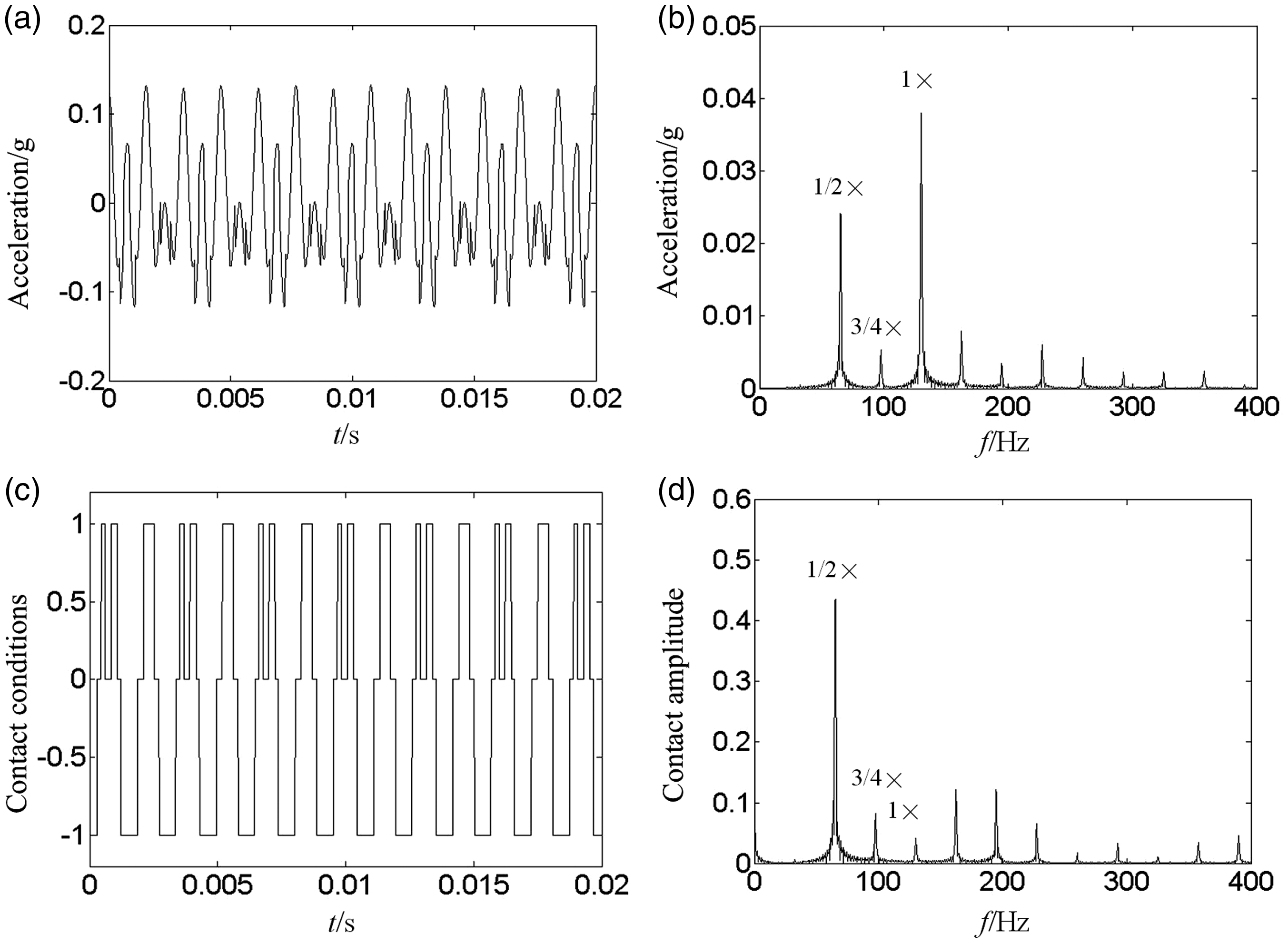
Acceleration wave, contact conditions, and their spectrums at 130 Hz. (a) Acceleration wave, (b) acceleration spectrum, (c) contact conditions, and (d) contact spectrum.
It is found that the odd and even order fractional frequencies and multiple frequencies are related to the contact numbers. Assuming the contact number as m, the odd and even order fractional frequencies and multiple frequencies can be expressed as follows

Equation (5) shows the relation between contact numbers and frequency components at subcritical and supercritical speeds. The contact number is even in an oscillating period and multi-frequencies appear when the rotating speed is at subcritical rotational speeds, otherwise, the contact number is odd in an oscillating period and fractional frequencies will appear. These fractional frequencies include odd and even order fractional frequencies when the rotating speeds are at supercritical speeds. It is not very clear to distinguish the odd and even order fractional frequencies from contact numbers in one oscillating period, but the fractional frequencies appear in frequency spectrum due to the contact incompatibility.
In order to better understand the contact mechanism, some waterfall and Campbell diagram are obtained. Figure 26 is the waterfall plot of rotor acceleration under subcritical frequencies from Wang et al. 2 Wang et al. 2 showed the mechanism of fractional and multi-frequencies from the aspect of stiffness changing period. However, the relation between fractional and multiple frequencies and contact numbers has not been fully explained. As shown in Figure 27, when the rotational frequency is at 5/4 or 7/4 times critical frequency, 1/4 fractional frequency component appear; referring to Figure 24, the contact number is five times in an oscillating period and the red line in figure will go through five rectangular zones to the diagonal points. When the rotational frequency is at 3/2 times critical frequency, 1/2 fractional frequency component appear; referring to Figure 23, the contact number is three times in an oscillating period and the blue line in figure will go through three rectangular zones to the diagonal points. When the rotational frequency is at three times critical frequency, 1/3 fractional frequency component appear; referring to Figure 25, the contact number is three times in an oscillating period and the yellow line in figure will go through three rectangular zones to the diagonal points.
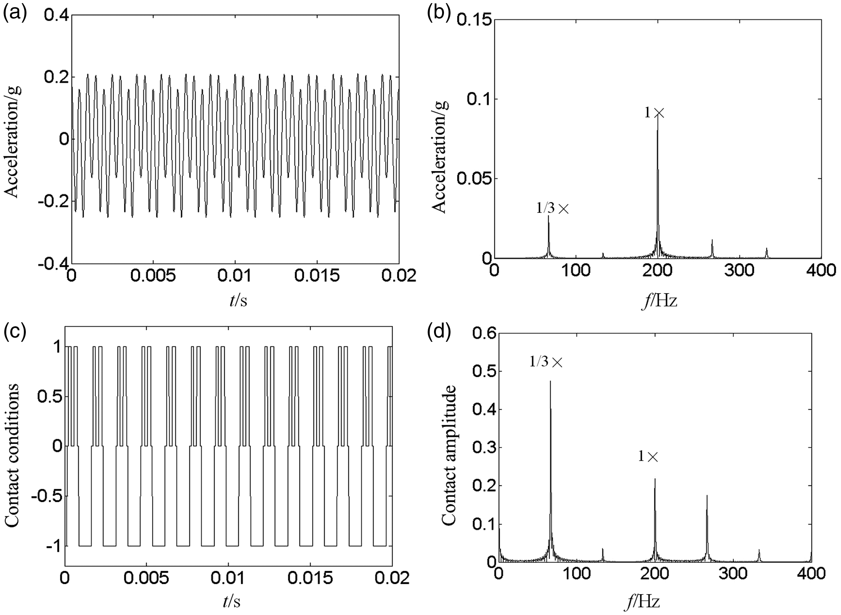
Acceleration wave, contact conditions, and their spectrums at 200 Hz. (a) Acceleration wave, (b) acceleration spectrum, (c) contact conditions, and (d) contact spectrum.
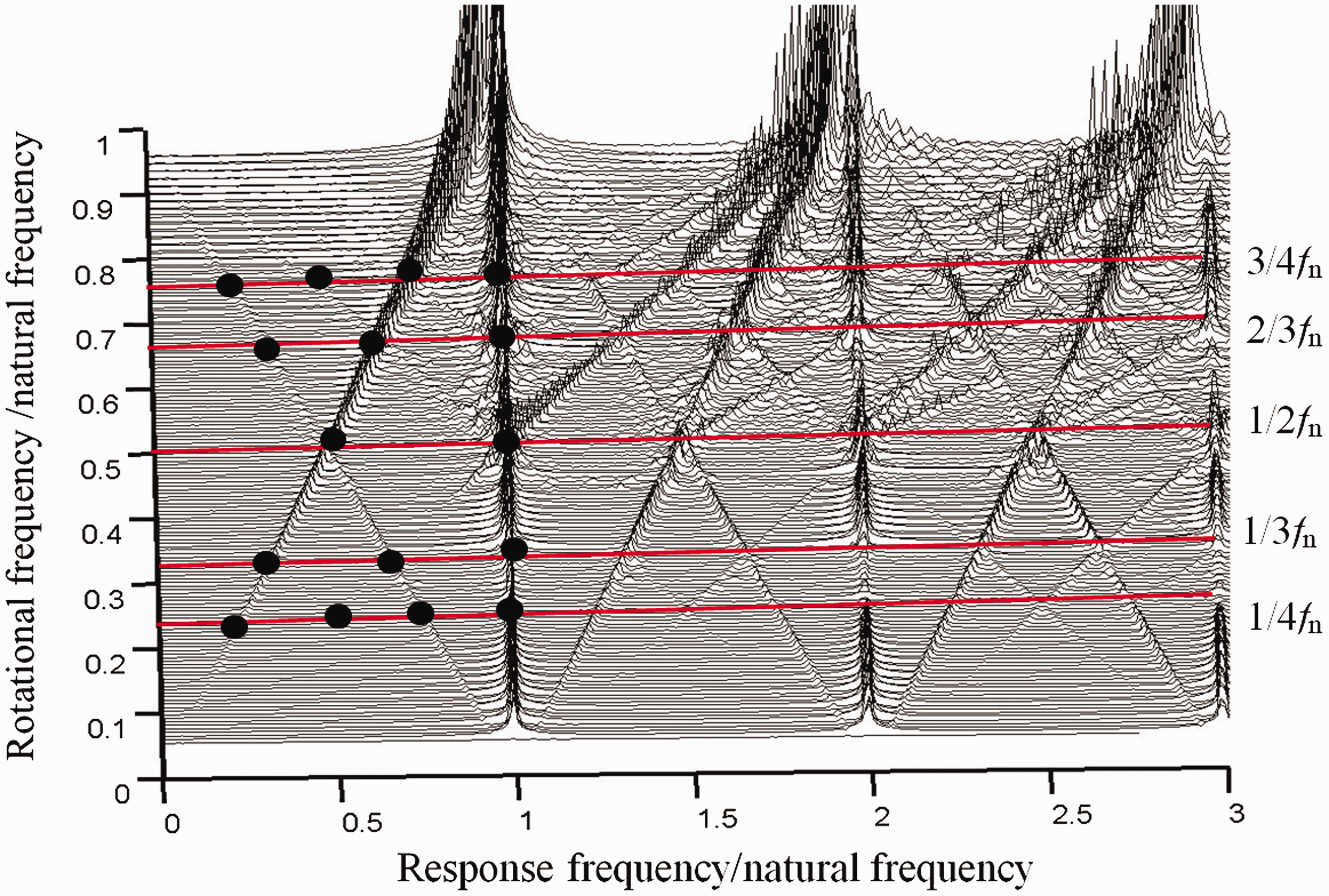
Cascade plot showing under subcritical speeds.
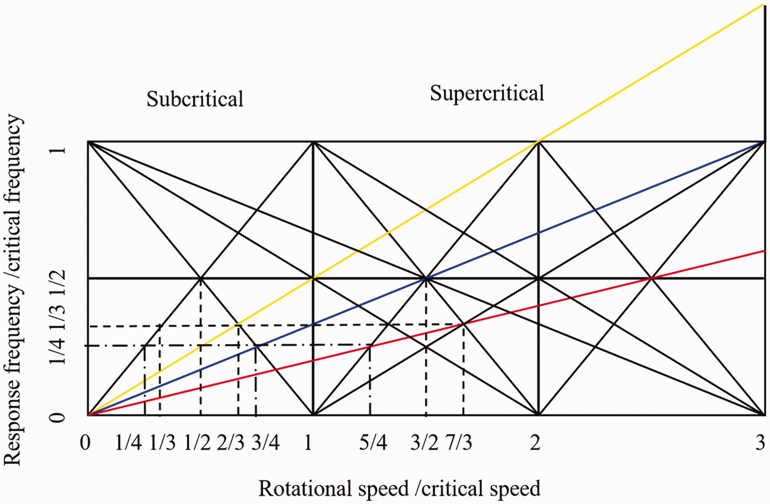
Campbell diagram showing inferred generalized subcritical and supercritical response.
The multi-frequencies such as 1×, 2×, 3× and fractional frequencies such as 1/2×, 1/3× are common in the acceleration response. It is essential to explain the mechanism of its generation. By comparing with the above results, some laws of frequency generation are obtained as follows. If the contact number in one period is even and the contact stiffness on upper surface and lower surface is different, multi-frequencies appear, otherwise, odd multi-frequencies appear due to the same stiffness of two contact surfaces.
If the contact number in one period is odd, that is there is one more contact on one surface than another surface, due to the contact incompatibility, odd and even fractional frequencies appear.
As for the elastic–plastic deformation, by comparing the results of model 1 and model 2, asymmetric stiffness on the contact surface makes it easier to get access to plastic stage. Plastic deformation makes larger displacement and the rotor system is in static deformation condition. Because the rotor system is just one degree of freedom, there is just one critical frequency. In the FEM model, the plastic deformation appears after the higher order frequency.
Conclusion
In this paper, a single degree of freedom lumped mass model with three different looseness faults is established. Some results are obtained as follows:
The plastic deformation makes the displacement amplitude increase rapidly. The displacement and acceleration keep harmonic vibration at the plastic deformation stage. In symmetric stiffness model, odd multi-frequencies appear, which is modulated by the inverse contacts of same stiffness; however, in asymmetric stiffness model, multi-frequencies appear. The mechanism of odd and even fractional order frequency generation is studied. When the contact number is odd, fractional frequencies appear at supercritical frequencies due to the incompatibility of contact numbers in upper and lower surface; however, when the contact number is even, multi-frequencies appear at subcritical frequencies.
Footnotes
Declaration of conflicting interests
The author(s) declared no potential conflicts of interest with respect to the research, authorship, and/or publication of this article.
Funding
The author(s) disclosed receipt of the following financial support for the research, authorship, and/or publication of this article: This work is supported by Chinese Scholarship Council with Granted No. 201708320058 and Funding of Scientific and Technological Innovation cultivating Program of Yangzhou University 2017CXJ022.