
Abstract
Dynamic characteristics of the asymmetric rotor system supported in axial-grooved gas-lubricated bearings are studied. In order to solve nonlinear dynamic response of rotor system effectively, a hybrid numerical model is established by coupling the motion equation of rotor with the rational function model of the gas film forces. The rational function model of the gas film forces of gas-lubricated bearing is established based on vector fitting theory. By using the hybrid numerical model, the repeated calculations of the unsteady Reynolds equation and gas film forces are avoided; the continuous rotor trajectory and the dynamic gas film forces can be calculated simultaneously; and for the rotor system supported in the same bearings, the computing cost can be saved effectively. The nonlinear dynamic responses of asymmetric rotor system supported in axial-grooved gas-lubricated bearings are investigated by trajectory diagrams, frequency spectrum, Poincaré maps, and time series. The bifurcations are analyzed by the bifurcation diagrams with different rotating speeds and mass eccentricities. The dynamic behaviors of the asymmetric rotor system appear complex nonlinear dynamic phenomenon and specific bifurcation characteristics.
Introduction
Gas-lubricated bearing has many outstanding advantages in the rotating machinery, such as high speed, high precision, low friction loss, low noise, and so on. The rotor system supported in gas-lubricated bearing has better performance. There are many studies about the stability and dynamic characteristics of the gas-lubricated bearing–rotor system.1-7 Wang et al. 8 analyzed the bifurcation and nonlinear dynamic behaviors of a flexible rotor supported by relative short gas film bearing, and the dynamic behaviors of the rotor system in the horizontal and vertical directions were investigated by the state trajectory, Poincaré maps, power spectra, and bifurcation diagrams. Li et al. 9 investigated the influence of the surface waviness on the nonlinear dynamic performance of a gas bearing–rotor system, and the stability of the rotor system was analyzed with different directions, the amplitudes, and the numbers of waves. Li et al. 10 established a dynamic model of the rotor–bearing system with bolted-disk joint by the proposed joint element and lumped mass modeling method, and the dynamic vibration characteristics and stability of rotor under different tangential stiffness and transition point were investigated. The gas-lubricated bearings above mentioned are cylindrical bearings. The rotor system supported in the gas-lubricated cylindrical bearing usually generates instability at higher speed.
In order to ensure stable operation and obtain higher performance, the grooved gas-lubricated bearings are employed. We 11 studied the unbalanced dynamic responses of the rotor system supported by three axial-grooved finitely long gas bearing. A time-dependent mathematical model was developed and solved by the differential transformation method. The influence of the nonlinear gas film forces on the stability of rotor system was investigated via analyzing the bifurcation and chaotic behaviors. We 12 proposed a calculation method coupling with the precise integration method for analyzing nonlinear dynamic behaviors of the self-acting axial groove gas bearing–rotor system with double time delays. The stability of the system can be improved via choosing the proper feedback control gains and the time delays. The whirl stability of the herringbone-grooved gas journal bearing was investigated by Fujita. 13 The critical stability of the bearing–rotor system with the change of bearing numbers was analyzed, which was determined by the rotor mass. The effects of the length-to-diameter ratio and the parameters of the groove on the whirl of a herringbone-grooved gas bearing were studied. Du et al. 14 analyzed the complicated nonlinear dynamic behaviors of the rotor–bearing system with a spiral-grooved opposed-hemisphere gas bearing support. The nonsynchronous excitation responses were analyzed differently from the way that the synchronous excitation responses were done. Han et al. 15 proposed a new parallel elastic hydrodynamic lubrication numerical algorithm. The lubrication performance of the misaligned herringbone-grooved axial bearing was investigated, and it can be improved via designing appropriate bottom shapes of herringbone grooves. Zhang et al. 16 investigated the effect of air rarefaction on air bearing forces and the contact behaviors of the air lubricated spiral-groove thrust micro-bearing. The bearing forces decreased and the asperity contact forces increase significantly by taking the air rarefaction into consideration. We 17 established a lubrication model of a micro-grooved three-pad fixing pad aerodynamic journal bearing. The effects of the parameters of the grooves in the bearing pad surfaces on the load performance of the three-pad aerodynamic bearing were investigated. By two-dimensional narrow groove theory, a model of a rigid rotor with herringbone-grooved journal gas bearing support was established by Liu et al. 18 The onset speed of the sub-synchronous vibration of the rotor system was predicted by the theoretical model and experimental data. In order to reduce the gas film vortex and oscillation and improve the operation stability of rotor system supported in spherical spiral groove hybrid gas bearing, Jia et al. 19 investigated the dynamic change of the gas film stiffness and damping coefficients under different motion conditions. The above studies focus on the dynamic characteristics of gas bearing–rotor system.
In order to calculate the dynamic response of bearing–rotor system more accurately and quickly, many novel models and methods were developed by scholars in the studies of the rotor dynamics. González et al. 20 presented a methodology to identify nonlinear instabilities of gas bearing–rotor system. The wavelets and phase diagram were obtained to estimate the nonlinear parameters and evaluate the dynamic behaviors. Hassini and Arghir 21 proposed a simplified method to investigate the nonlinear transient behaviors of a flexible rotor with the gas bearing support. The large nonlinear displacements, stability diagrams, and Campbell diagrams were obtained by their proposed method which approximates the impedances using rational functions. Bonello 22 developed a linearized method of the foil air bearing symmetric rigid rotor system based on the system Jacobi, and the effects of air film constraints and top foil detachment on the bearing–rotor system were investigated by using the proposed method. By considering the micro-deformation and interaction of various foils, Zhou et al. 23 presented a semi-directly experimental method of the bump-type foil journal bearing. The dynamic behaviors of the rotor–bearing system were predicted by analyzing the journal orbits. Baum et al. 24 established a novel physical and mathematical model to investigate the rotor dynamic characteristics of a rigid rotor with the foil air bearing support; the dimension of the model was reduced by Galerkin’s method, and the computational cost of the dynamic characteristics can be reduced by the proposed model.
Many different analysis methods of the nonlinear stability have been developed. Yang et al. 25 investigated the unbalance response of micro-gas bearing–rotor system; the results showed that stability threshold speed of micro-rotor system increased by considering the gas rarefaction effect. He et al. 26 adopted a new technique of the nonlinear expanded frequency to attain the stability criteria; the nonlinear stability of the Kelvin Helmholtz instability saturated in porous media with heat and mass transfer was investigated. Based on the homotopy perturbation method, He et al. 27 proposed a reducing rank approach to solve the strongly damping nonlinear Klein–Gordon equation; the stability conditions were established for the first time; and the stability analysis was discussed. Sun et al. 28 investigated the stability of a magnetic bearing supported rotor system with significant gyroscopic effects by using the double-frequency Bode plot and the Nyquist criterion. Guo et al. 29 proposed a dynamic model of a hydrodynamic floating ring bearing to study the influence of lubricant temperature–viscosity on the performance, and the stability criterion was obtained by the Routh–Hurwitz method.
In this paper, a hybrid numerical model of asymmetric rotor system supported in two axial-grooved gas-lubricated bearings is established to calculate the nonlinear dynamic responses and bifurcation of gas-lubricated bearing–rotor system efficiently. The rational function model of gas-lubricated bearing is established by the rational function approximation theory and vector fitting method. The hybrid numerical model is coupling of the rational function model with motion equation of rotor. The nonlinear dynamic responses of gas-lubricated bearing–rotor system are obtained by solving the hybrid numerical model, and the bifurcations are calculated under the conditions of different rotating speeds and mass eccentricities.
Model and Method
Model of gas-lubricated bearing
The schematic diagram of the gas-lubricated bearing is shown in Figure 1. O
b
and O
j
are the bearing and journal centers, respectively, Schematic diagram of two axial-grooved gas-lubricated bearings.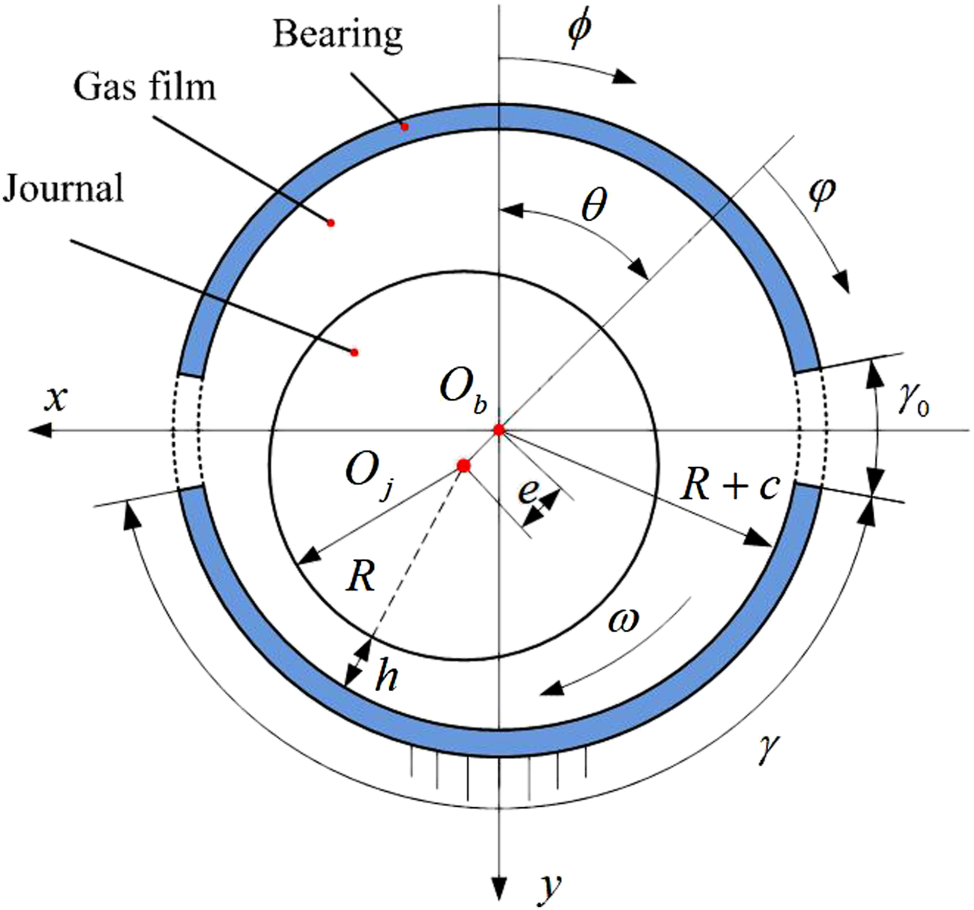
For gas-lubricated bearing, the nondimensional steady compressible Reynolds equation is

The nondimensional boundary conditions of the Reynolds equation are
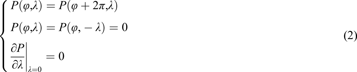
The steady Reynolds equation is solved by FDM (finite difference method).
Dynamic coefficients of gas-lubricated bearing
The static gas film pressure P0 of gas-lubricated bearing at steady equilibrium position is solved by computing iteratively the steady Reynolds equation. The dynamic gas film pressure P
d
is caused by the journal deviating from steady equilibrium position due to the small perturbation. The position of the journal at any time can be expressed as
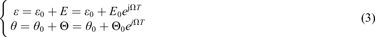
With the small perturbation of the journal, the dynamic gas film thickness and pressure between gas-lubricated bearing and journal can be written as

The differential of dynamic gas film forces with respect to perturbation amplitude of eccentricity and attitude angle can be expressed as
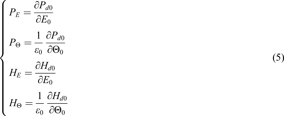
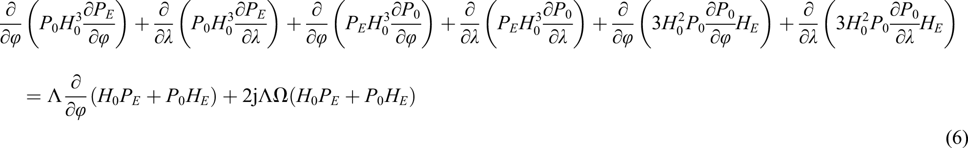
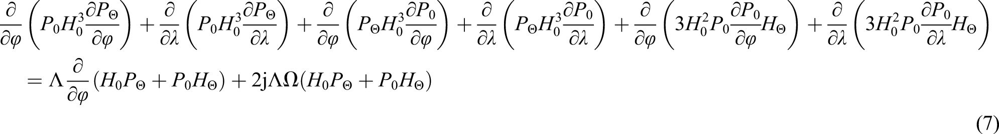
By substituting the equation (4) into the Reynolds equation, and taking the derivative with respect to E0 and Θ0, the partial differential equations (6) and (7) can be obtained. P
E
and PΘ can be calculated by solving the partial differential equations
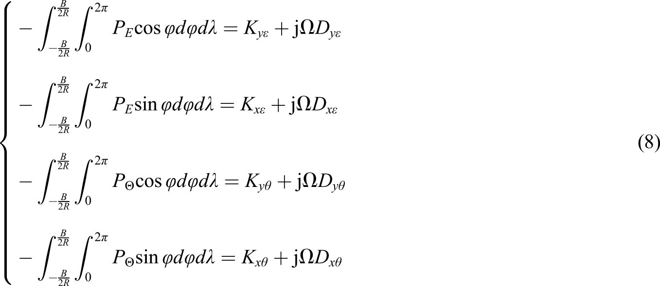
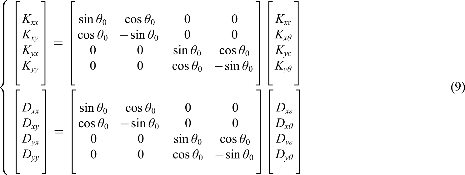
The dynamic stiffness and damping coefficients of gas-lubricated bearing can be expressed as equation (8) by the differential of dynamic gas film forces P
E
and PΘ. The dynamic stiffness and damping coefficients in the x and y directions can be obtained by the transformation matrix
The impedance of gas film forces can be obtained by a complex number form of dynamic stiffness and damping coefficients

Rational function approximation of impedance
Impedance of the gas-lubricated bearing
According to the definition of impedance, the impedance Z(s) can be expressed as the differential of the perturbation gas film force versus small perturbation amplitude

Fitting of the rational function coefficients
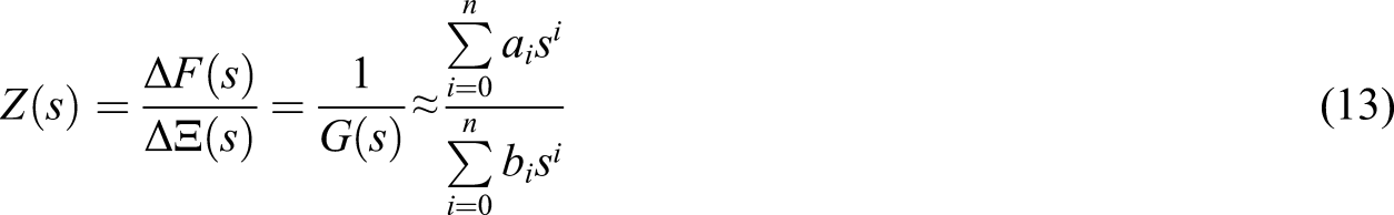
According to the response relationship between ΔF(s) and ΔΞ(s), the transfer function can be expressed as rational fractions
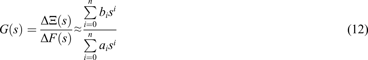
By combining equation (11) with equation (12), the approximate expression of the impedance Z(s) using rational function is as follows
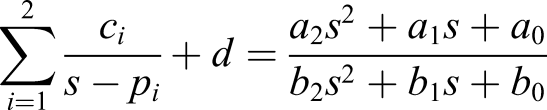
According to partial fraction expansion, the rational function can be expressed as the sum of several rational fractional functions, and the impedance Z(s) is in the following form

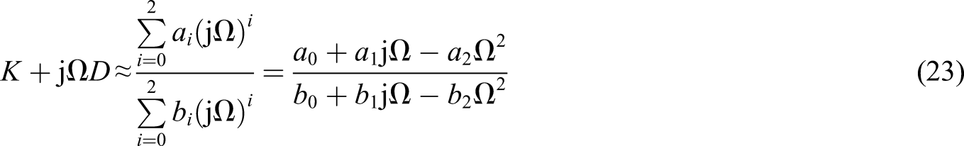
For the rational fractional functions, taking n = 2, the impedance Z(s) is approximated as a second-order rational function in the following form

The calculation process of rational function unknown coefficients is as follows: 1. A set of initial poles
The initial poles 2. Calculation of the unknown coefficients of impedance Z(s).

The rational function δ(s) with the same poles

By multiplying the rational functions δ(s) and Z(s), the following equation can be obtained
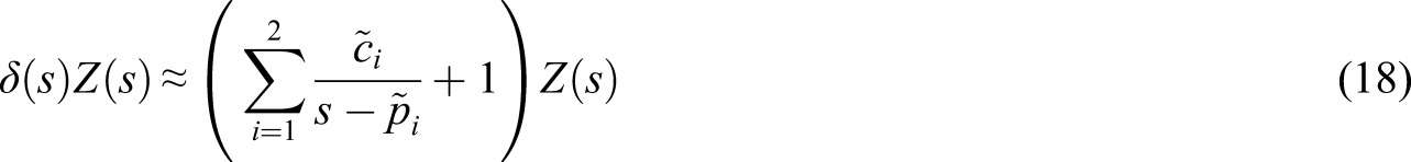
δ(s)Z(s) can be approximated to a new rational function which is similar to equation (15)

Equation (19) can be written as

Equation (20) can be expressed as the overdetermined equation

Z(s) is known, and the unknown coefficients c
i
,
By setting the initial poles 3) To solve the rational function coefficients of impedance Z(s).
According to equation (13), the second-order rational function fraction of impedance Z(s) is

By solving equations (15) and (22) simultaneously, the following equation can be obtained
Z(s)=Z(jΩ) is approximated by second-order rational fractions, according to equations (10) and (22), and the stiffness and damping coefficients can be expressed as
The stiffness coefficient K and damping coefficient D
31
can be expressed as the following


Hybrid model of the bearing–rotor system
Motion equation of the rotor
Figure 2 shows the schematic diagram of the asymmetric rotor system supported in axial-grooved gas-lubricated bearings. The asymmetric rotor is composed of five segments of different lengths and diameters; the gas-lubricated bearings 1 and 2 are mounted on the segments 1 and 5 separately. O1 and O2 are the journal centers of gas-lubricated bearings 1 and 2 separately; O is the mass center of asymmetric rotor; m is the mass of rotor; l1 and l2 are the distances between the mass center and the journal centers at bearing 1 and 2 stations separately, l = l1+l2. Schematic diagram of gas-lubricated bearing–asymmetric rotor system.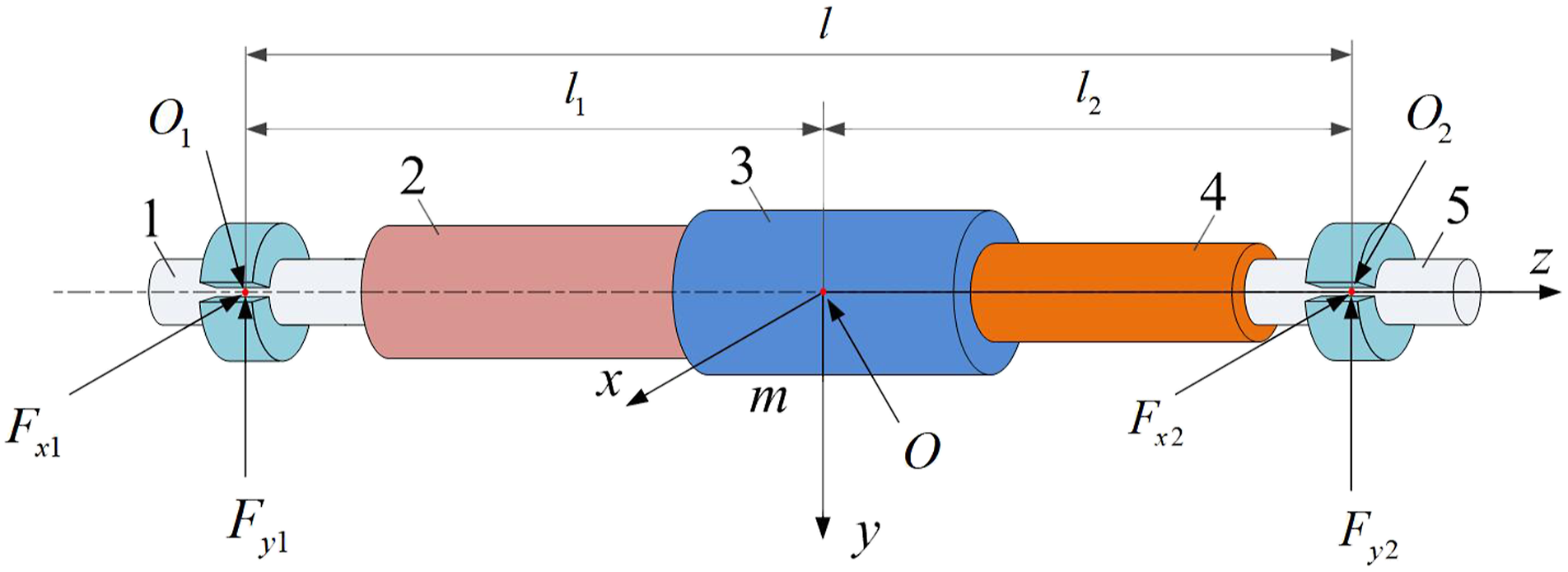
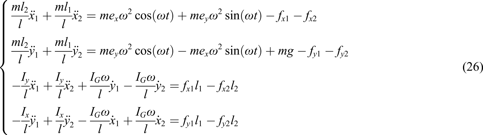
The motion equation of asymmetric rotor system is
By introducing the following nondimensional variables, Pa is the ambient pressure and R is the radius of the journal
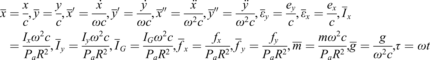
The nondimensional equation of asymmetric rotor system can be obtained as follows
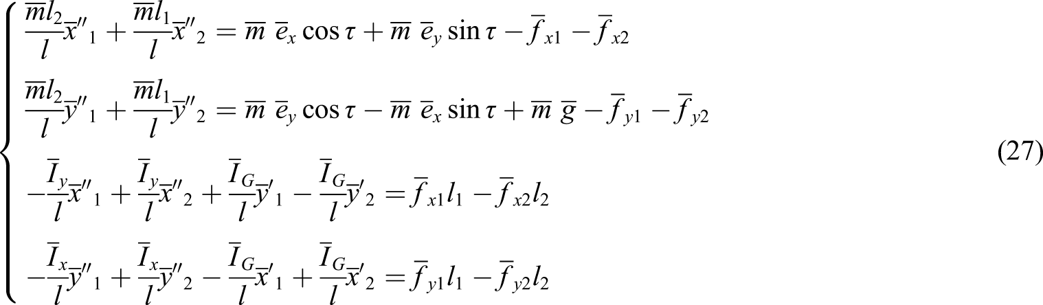
In order to calculate the displacements of the journal centers of motion equation (27), the unsteady Reynolds equation and nonlinear gas film forces need to be solved at each step. The multiple iteration results in higher computing cost.
Rational function model of gas film forces
Equation (13) is the rational function equation in frequency domain, and the relation between disturbance increment and response increment can be transformed into time domain by inverse Fourier transform; the equation in the time domain can be obtained as follows

Because the direct and cross coupled impedances share same poles, b
i
xx
=b
i
xy
=b
i
yx
=b
i
yy
=b
i
. By expanding equation (28) in the x and y directions, equation (29) can be obtained
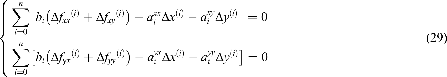
According to the relationship of gas film force components in the x and y directions, equation (30) can be expressed as
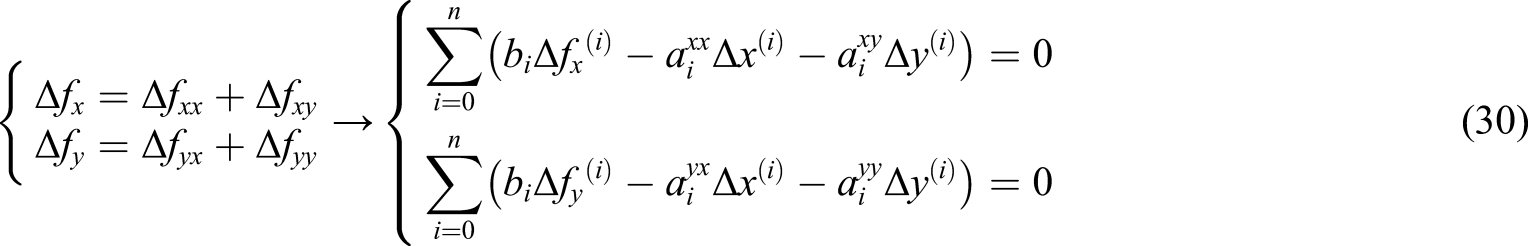
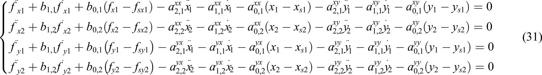
The rational function model of gas-lubricated bearing is established by equation (30), which is coupled with journal displacements. The second-order expansion equations at bearing 1 and 2 stations are
Hybrid model of gas-lubricated bearing–rotor system
Equation (31) is converted into nondimensional form and coupled with the nondimensional motion equation of rotor. A hybrid numerical model of the rotor supported in gas-lubricated bearing is established. The hybrid dynamic equation is

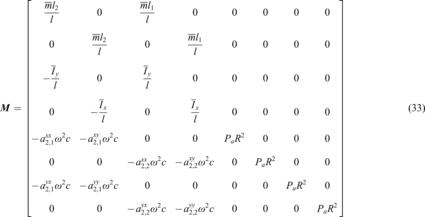
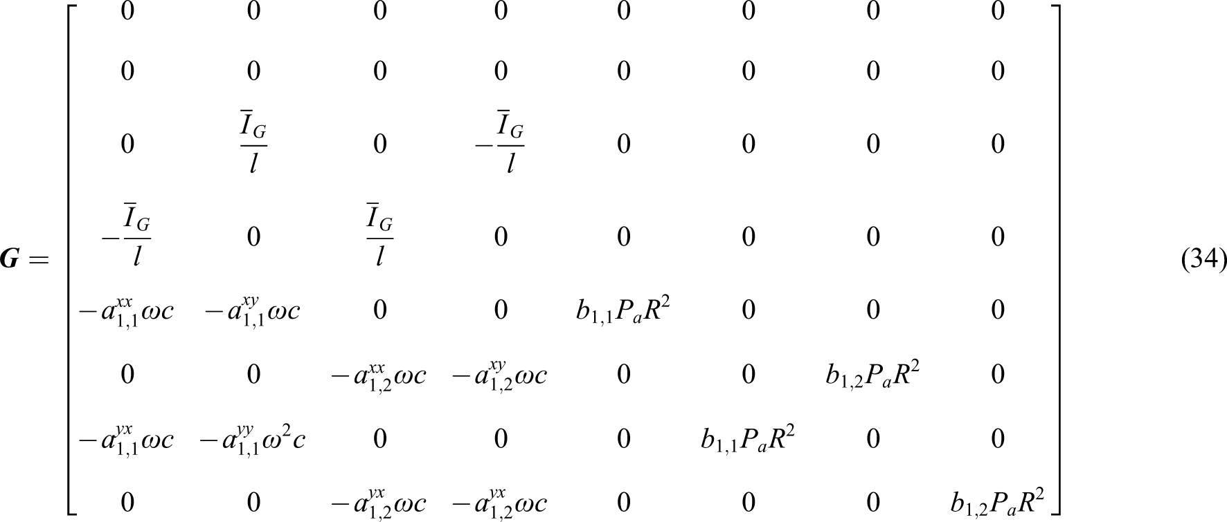
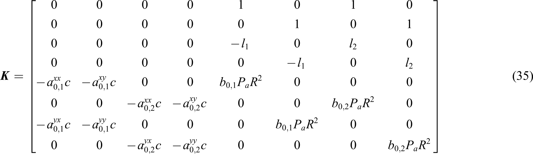
The trajectories of journal centers and the gas film forces in the x and y directions at bearing 1 and 2 stations can be calculated by solving the hybrid numerical model simultaneously when the rational function coefficients a i and b i are known. In the computational process, the multiple iterations are avoided and the computing cost is reduced greatly. Because the rational function coefficients are same as long as the structural parameters of the bearing are unchanged, for the rotor system of different structures or parameters supported in same bearing, the rational function coefficients do not need to be recalculated.
Stability analysis
The motion equation of the rotor system can be written as
By substituting equation (38) into equation (37), equation (39) can be obtained
Equation (39) has untrivial solutions when the determinant equation of equation (39) equals to 0, as follows

Numerical results
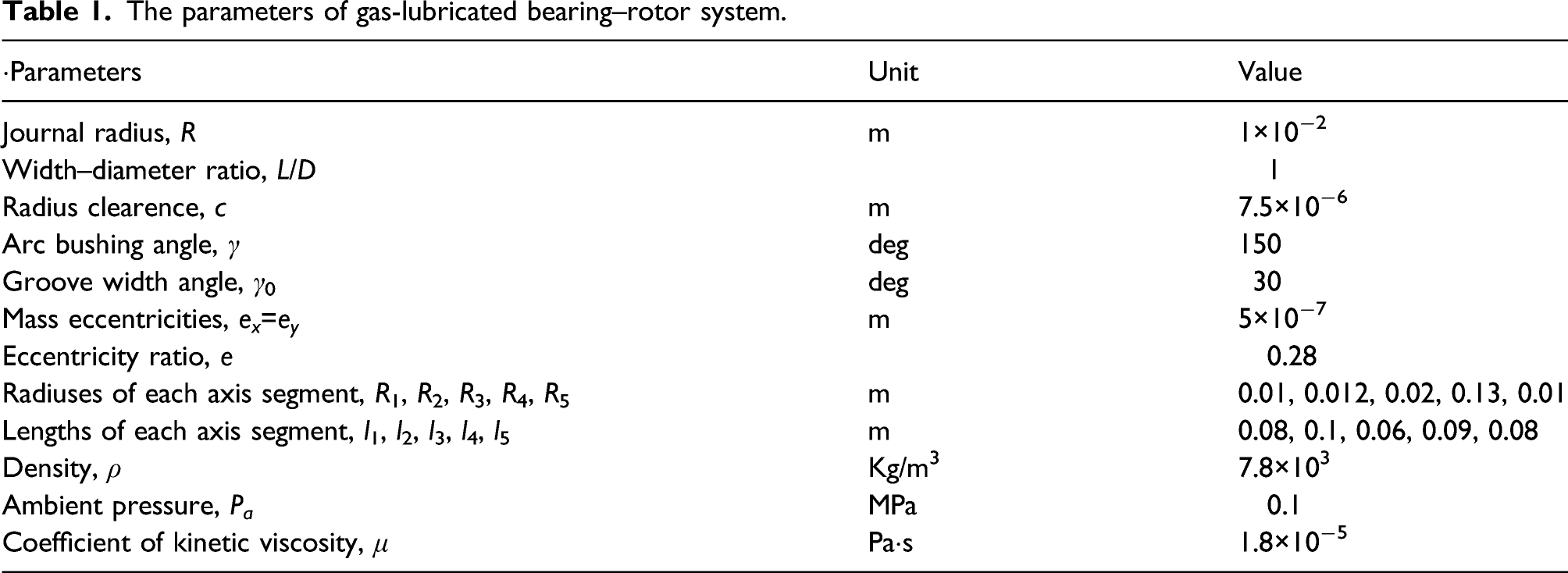
The parameters of gas-lubricated bearing–rotor system.
Verification
Figure 3 is the time series of the journal centers at bearing 1 and 2 stations solved by the proposed hybrid numerical model and the ones obtained by solving the transient Reynolds equation and the rotor motion equation (27) by the Newmark-β method at rotating speed ω=1000 rad/s. By comparison of the trajectories of journal centers, the result obtained by the hybrid numerical model is in good agreement with the Newmark-β method. The computing time required by the hybrid numerical model and Newmark-β method is 521 s and 1972 s, respectively. It can be seen that the computing cost is reduced by the proposed hybrid numerical model. Comparison of time series of Y of journal centers at bearing 1 and 2 stations: (a) At bearing 1 station and (b) at bearing 2 station.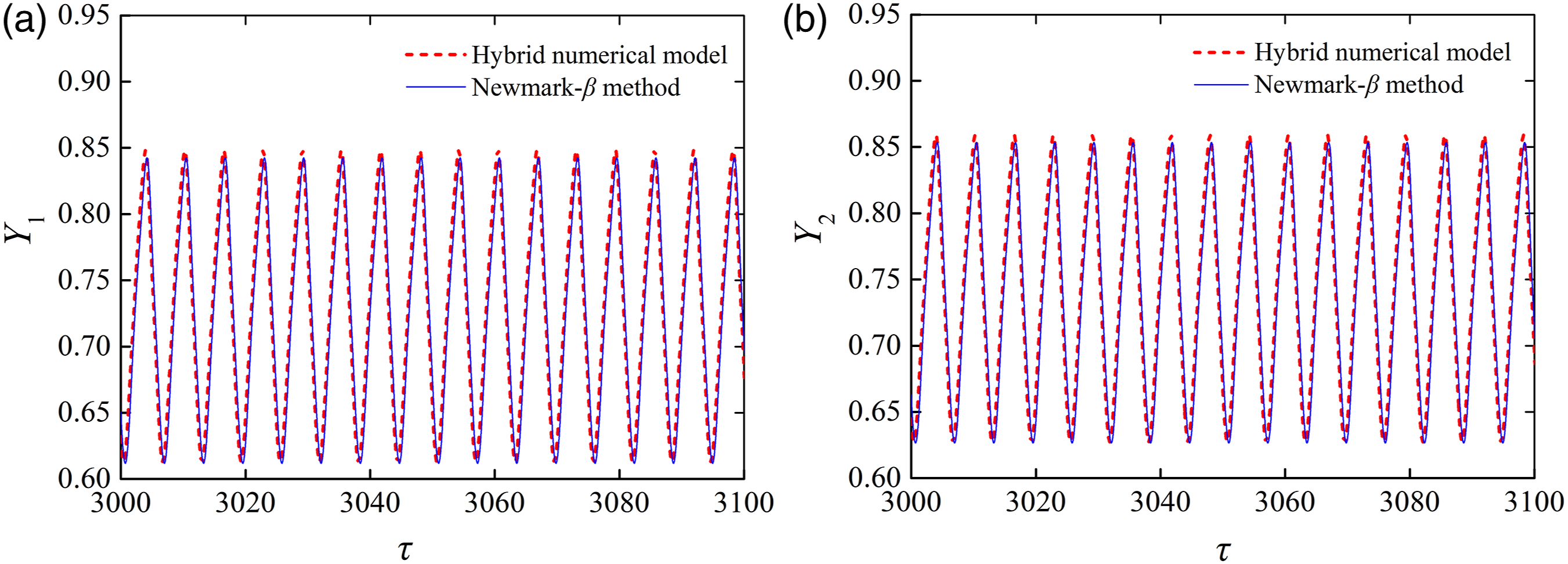
Dynamic response versus rotating speed
The nonlinear dynamic responses of asymmetric rotor system supported by two axial-grooved gas-lubricated bearings are complex and diverse with the change of rotating speed. The bifurcation characteristics of gas-lubricated bearing–rotor system for ω=500–3700 rad/s are shown in Figure 4. It can be seen that the bearing–rotor system has periodic, period-doubling, and quasi-periodic responses. When ω=500–1050 rad/s, the motions of the journal center are quasi-periodic at bearing 1 station. The amplitudes of the trajectories decrease with the increase of rotating speed. When ω=1100 rad/s, the quasi-periodic motion of journal center becomes periodic motion. When the rotating speed increases to 1850 rad/s, the periodic motion bifurcates to period-doubling motion. The period-doubling motion bifurcates inversely to periodic motion for ω=2250 rad/s. When ω=3160 rad/s, the periodic motion bifurcates to quasi-periodic motion, but when ω=3150, 3340, and 3350 rad/s, the motions of the journal center are period-14 motions. When the rotating speed increases to 3475 rad/s, the quasi-periodic motion of gas-lubricated bearing–rotor system turns into period-doubling motion. When ω = 500–3700 rad/s, the bifurcation diagram of journal center at bearing 1 station.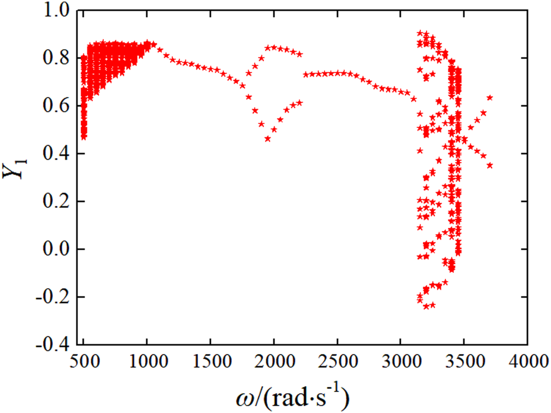
Figure 5(a) and (b) shows the motion bifurcations of gas-lubricated bearing–rotor system, which are from quasi-periodic motion to periodic motion and from quasi-periodic motion to period-doubling motion, respectively. It is worth noting the quasi-periodic motion bifurcates to multi-periodic motion and then turns into quasi-periodic motion; the quasi-periodic motion bifurcates to period-doubling motion with the increase of rotating speed. The bifurcation diagram of journal center at bearing 1 station: (a) ω = 900–1500 rad/s and (b) ω = 3400–3600 rad/s.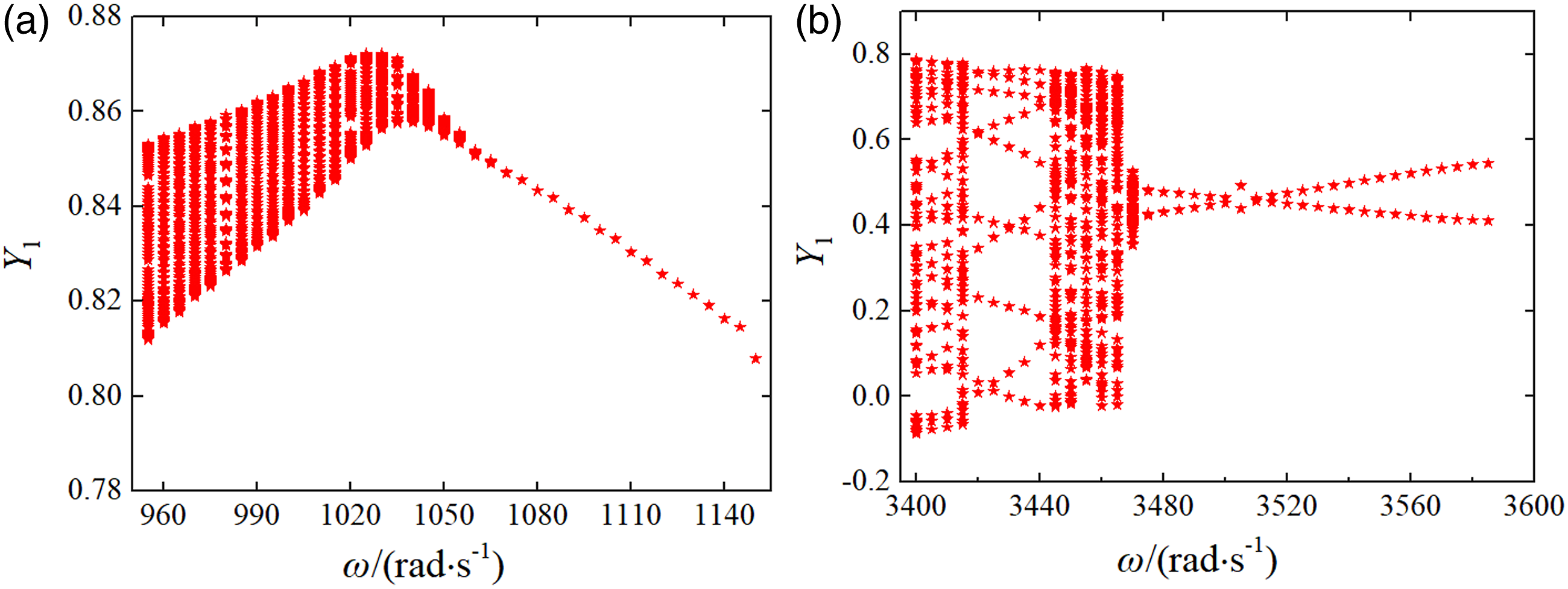
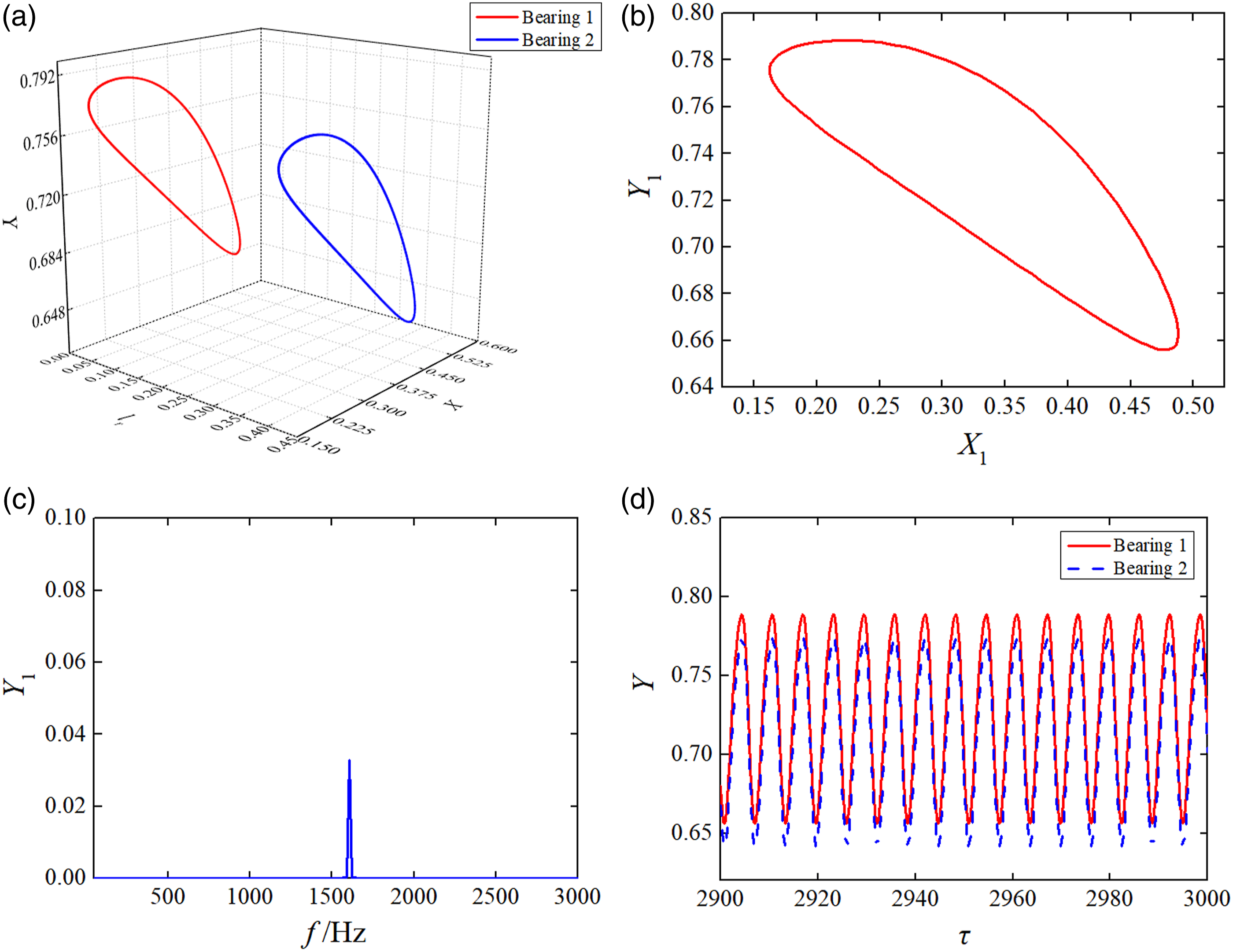
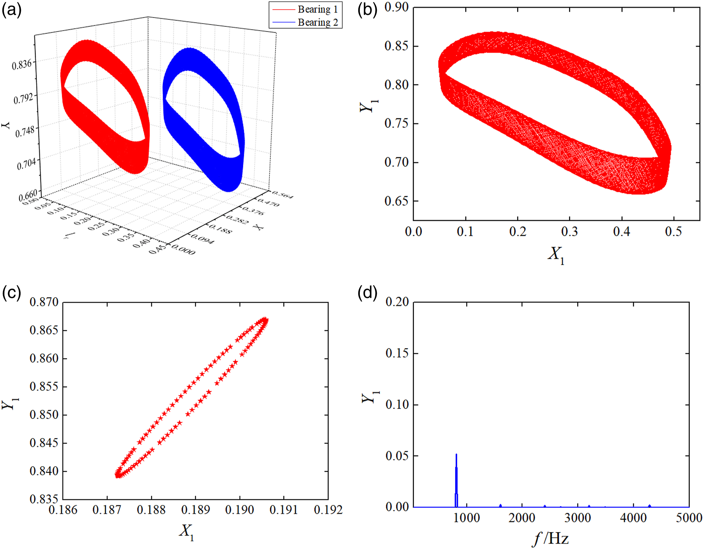
When ω=1000 rad/s, the quasi-periodic motions of the journal centers at bearing 1 and 2 stations are shown in Figure 6. Figure 6(a) and (b) shows the nondimensional trajectories of journal centers; as can be seen, the motions of journal centers are different at bearing 1 and 2 stations due to the gyroscopic effect. Figure 6(c) shows that the projection of the Poincaré map on the X-Y plane is torus attractor, and the spectrum is discrete in Figure 6(d). The time series of journal centers at bearing 1 and 2 stations are shown in Figure 6(e). For ω=1500 rad/s, the dynamic response of gas-lubricated bearing–rotor system is shown in Figure 7(a) at bearing 1 and 2 stations. As shown in Figure 7(b) and (c), the trajectory of journal center is periodic motion, and the spectrum is discrete. When ω = 1000 rad/s, the quasi-periodic motions of journal centers at bearing 1 and 2 stations: (a) Trajectories of journal centers; (b) comparison of trajectories of journal centers; (c) Poincaré map of journal center; (d) spectrum diagram of journal center; and (e) time series of journal centers. When ω = 1500 rad/s, the periodic motions of journal centers at bearing 1 and 2 stations: (a) Trajectories of journal centers; (b) trajectory of journal center at bearing 1 station; (c) spectrum diagram of journal center; and (d) time series of journal centers.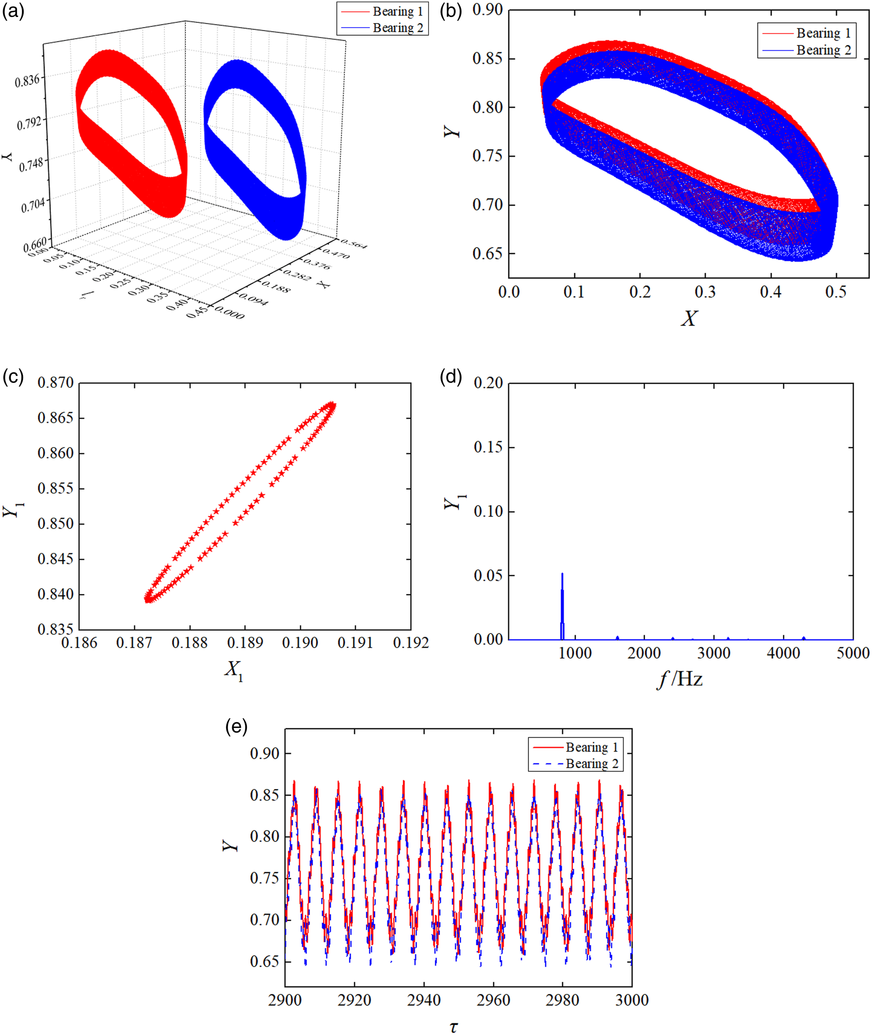
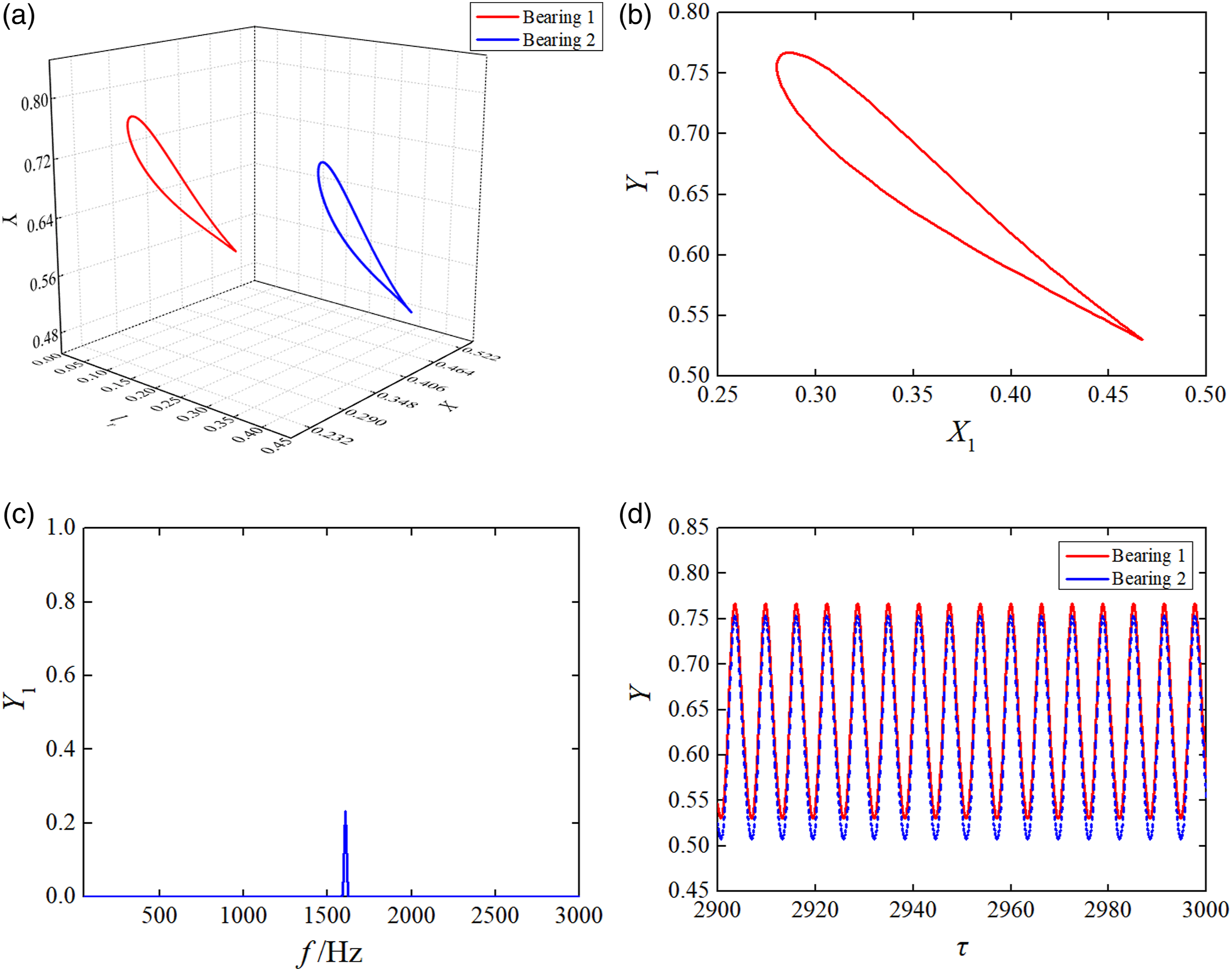
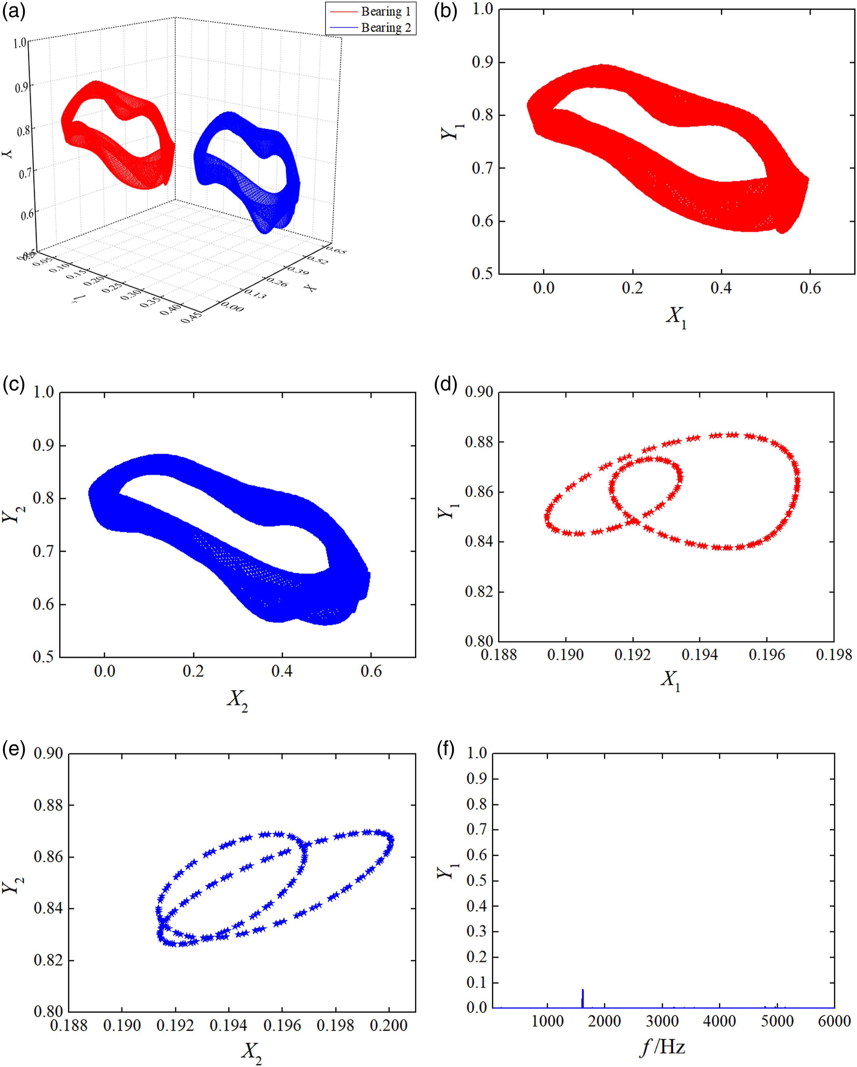
When ω=2000 rad/s, the periodic motions of journal centers bifurcate to period-doubling motions at bearing 1 and 2 stations, which are shown in Figure 8(a) and (b). The Poincaré map has two projection points on the X-Y plane, as shown in Figure 8(c). The spectrum diagram contains two spectral components, as shown in Figure 8(d). For ω=2500 rad/s, it can be seen that the period-doubling motions of the journal centers bifurcate inversely to periodic motions at bearing 1 and 2 stations in Figure 9. As shown in Figure 9(a)–(c), the trajectory of journal center is periodic motion, and the spectrum diagram contains one spectral component. When ω = 2000 rad/s, the period-doubling motions of journal centers at bearing 1 and 2 stations: (a) Trajectories of journal centers; (b) trajectory of journal center; (c) Poincaré map of journal center; (d) spectrum diagram of journal center; and (e) time series of journal centers. When ω = 2500 rad/s, the periodic motions of journal centers at bearing 1 and 2 stations: (a) Trajectories of journal centers; (b) trajectory of journal center; (c) spectrum diagram of journal center; and (d) time series of journal centers.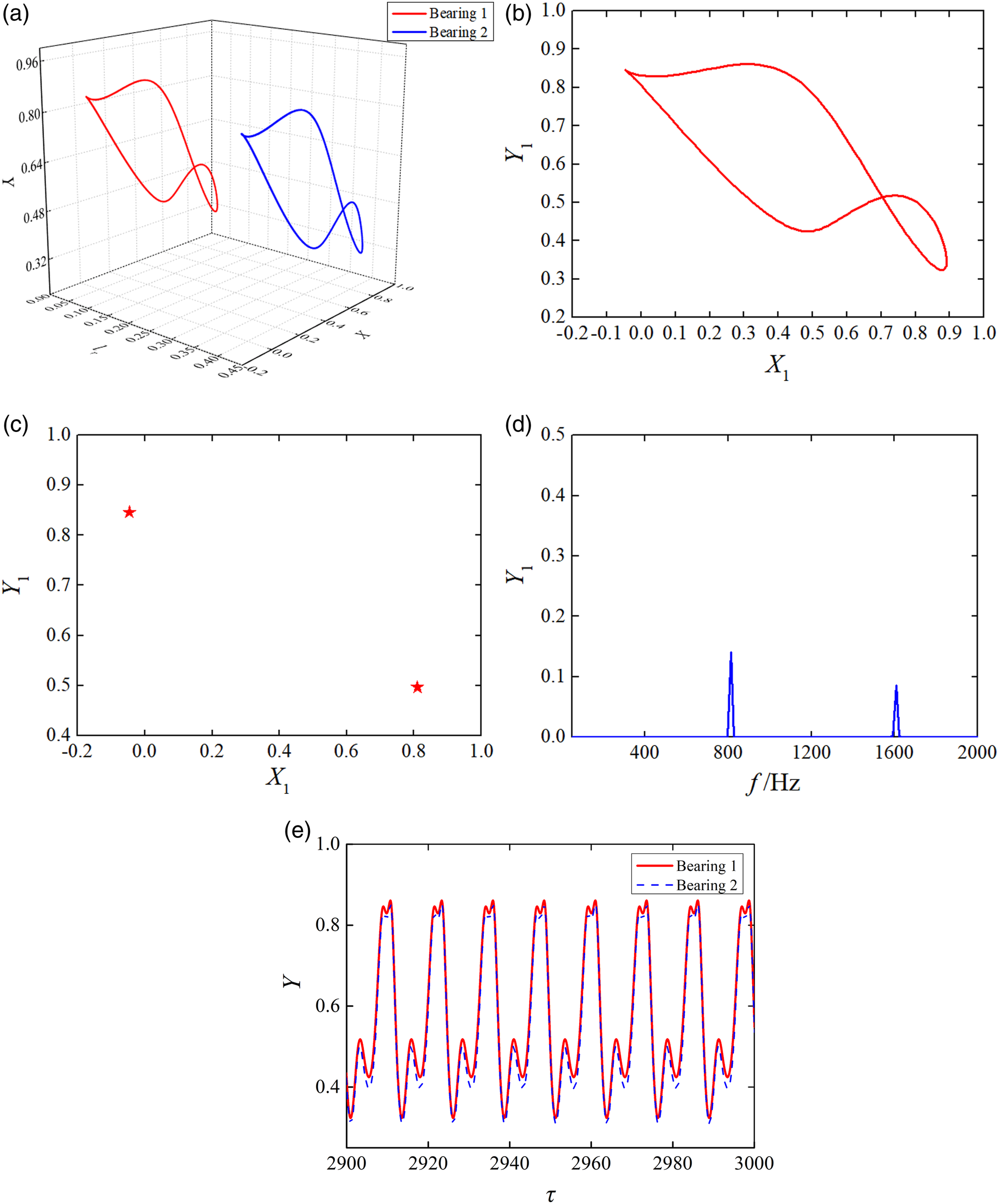
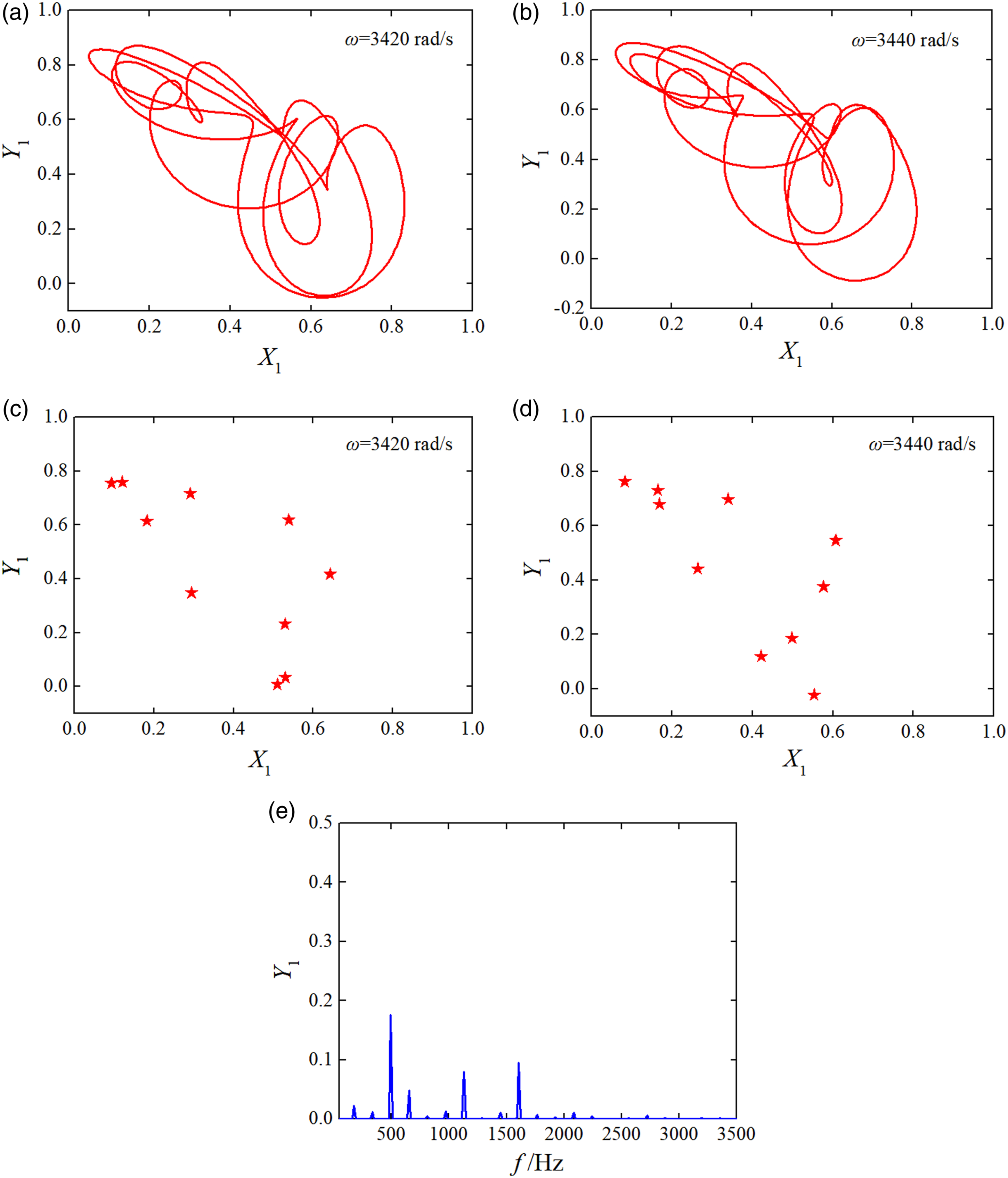
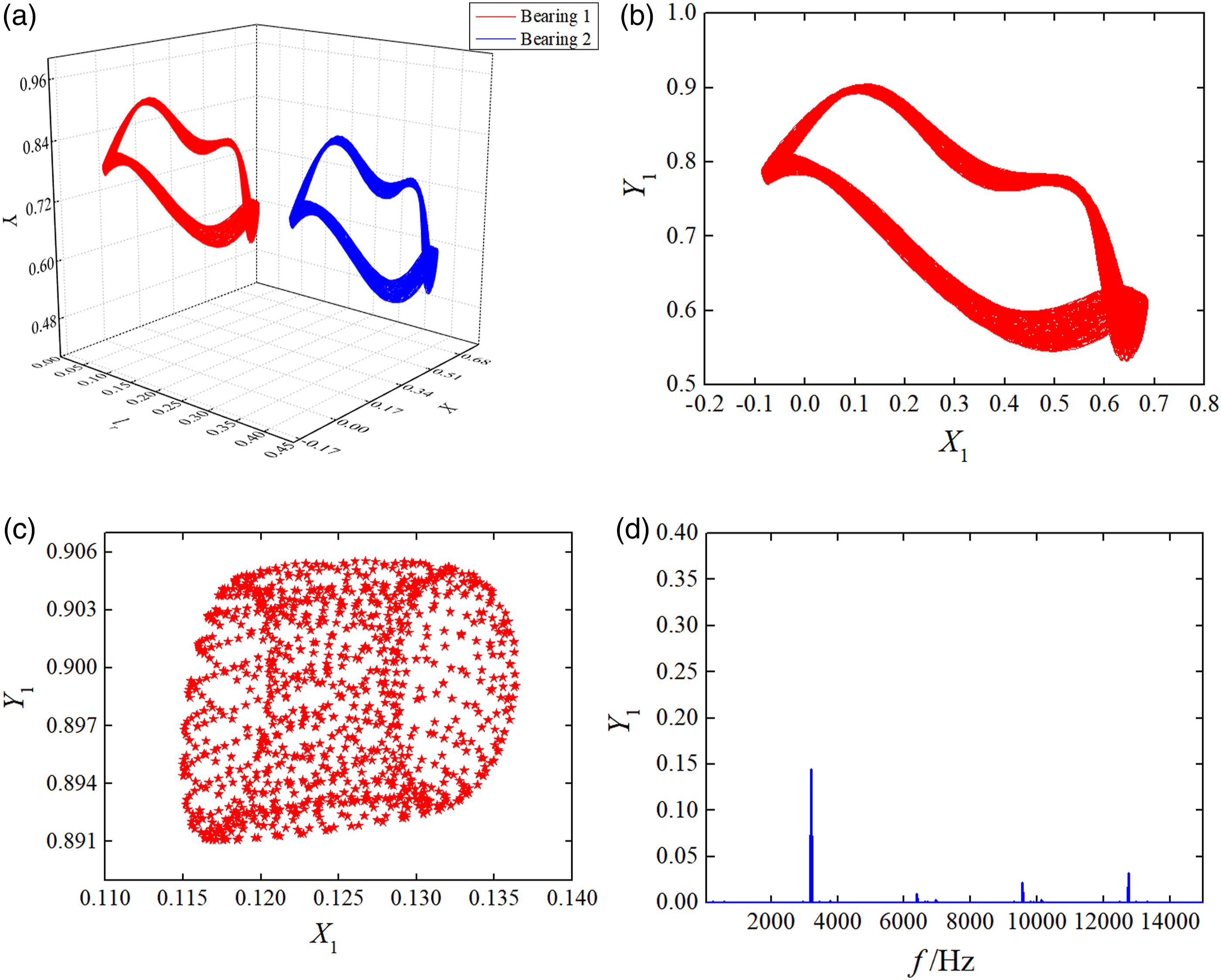
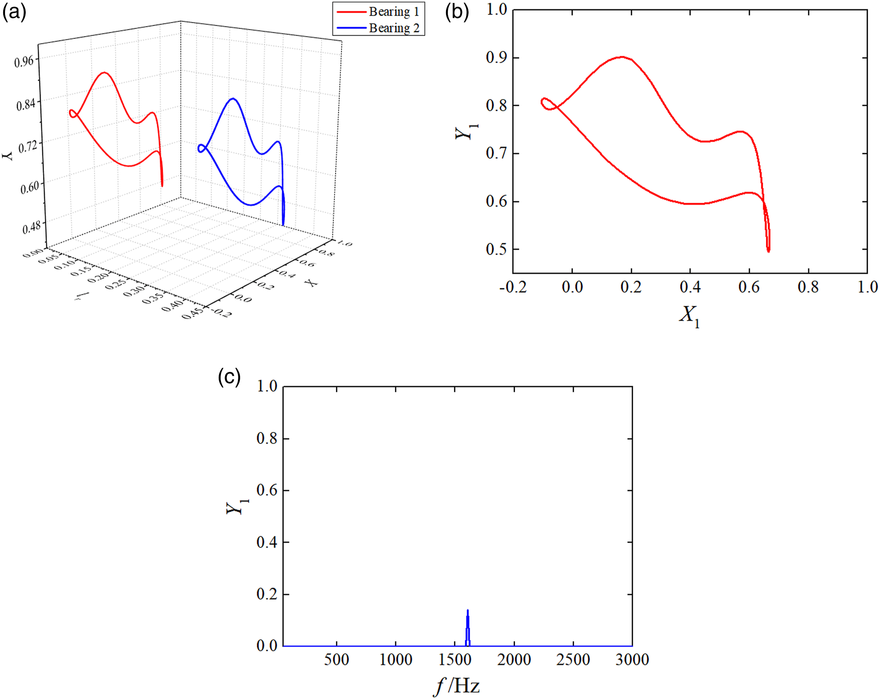
For ω=3400 rad/s, the dynamic response of gas-lubricated bearing–rotor system is shown in Figure 10. The periodic motions of journal centers bifurcate to quasi-periodic motions at bearing 1 and 2 stations, which are shown in Figure 10(a). The trajectory of journal center at bearing 1 station is shown in Figure 10(b), and the trajectory of journal center at bearing 2 station is similar with the trajectory at bearing 1 station. The Poincaré maps of journal centers at bearing 1 and 2 stations are shown in Figure 10(c)–(d), and the projections of the Poincaré maps on the X-Y plane are torus attractors. The spectrum diagram shows as discrete spectrum in Figure 10(e). When the rotating speed increases to 3420 and 3440 rad/s, the quasi-periodic motions become to period-10 motions shown in Figure 11. Figure 11(a)–(d) show the trajectories and Poincaré maps of journal centers at bearing 1 station; the Poincaré maps have 10 projection points on the X-Y plane in Figures 11(c) and (d), and the spectrum diagram is shown as discrete spectrum in Figure 11(e). When ω = 3400 rad/s, the quasi-periodic motions of journal centers at bearing 1 and 2 stations: (a) Trajectories of journal centers; (b) trajectory of journal center; (c) Poincaré map of journal center at bearing 1 station; (d) Poincaré map of journal center at bearing 2 station; (e) spectrum diagram of journal center; and (f) time series of journal centers. When ω=3420 and 3440 rad/s, the period-10 motions of journal center at bearing 1 station: (a) Trajectory of journal center for ω=3420 rad/s; (b) trajectory of journal center for ω = 3440 rad/s; (c) Poincaré map of journal center for ω=3420 rad/s; (d) Poincaré map of journal center for ω=3440 rad/s; and (e) spectrum diagram of journal center for ω = 3420 rad/s.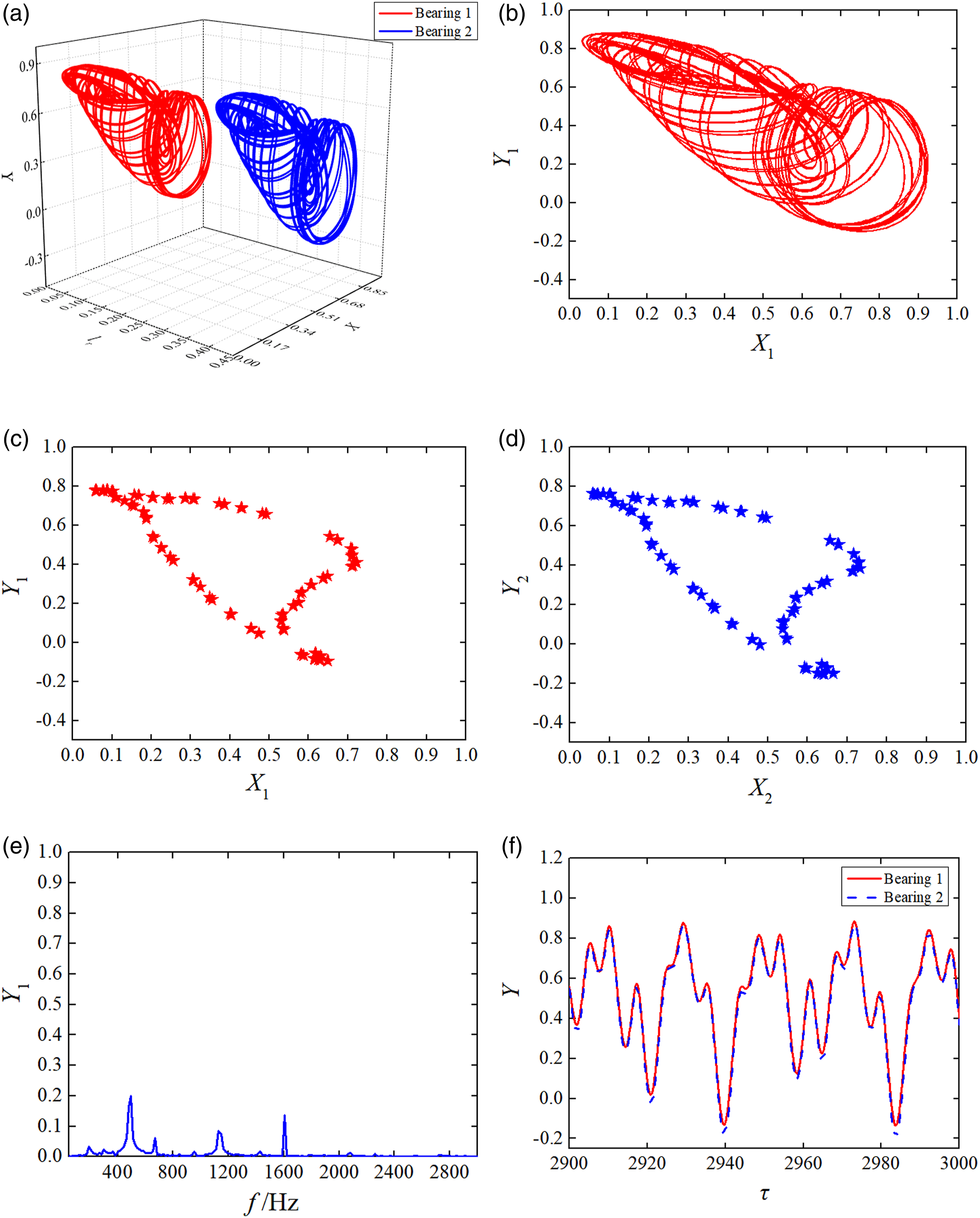
When ω=3500 rad/s, the dynamic response bifurcates inversely to period-doubling motion from quasi-periodic motion, as shown in Figure 12(a). The trajectories of journal centers at bearing 1 and 2 stations are shown in Figures 12(b) and (c). Figures 12(d) and (e) depict the Poincaré map and spectrum diagram of journal center at bearing 1 station; the projections of the Poincaré map on the X-Y plane are two fixed points; and the spectrum diagram contains two spectral components. When ω = 3500 rad/s, the period-doubling motions of journal centers at bearing 1 and 2 stations: (a) Trajectories of journal centers; (b) trajectory of journal center at bearing 1 station; (c) trajectory of journal center at bearing 2 station; (d) Poincaré map of journal center; (e) spectrum diagram of journal center; and (f) time series of journal centers.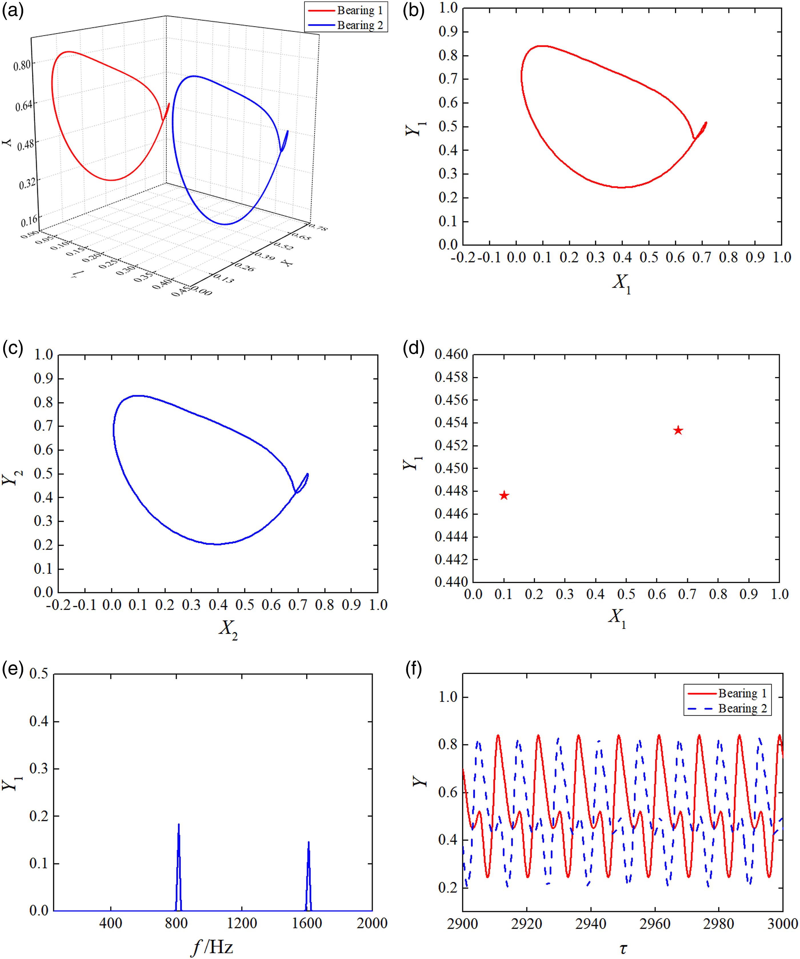
Dynamic response versus mass eccentricity
As can be seen in Figure 13, the bifurcation diagram shows the nondimensional vertical motion of journal center at bearing 1 station, which is plotted versus unbalance mass eccentricities. The dynamic responses of gas-lubricated bearing–rotor system are periodic motions when the mass eccentricities e
x
and e
y
are less than 4.5×10⁻⁷ m, and the periodic motions of journal center at bearing 1 station bifurcate to quasi-periodic motions when e
x
=e
y
=4.5×10⁻⁷ m, with the increase of mass eccentricities. When ω = 1000 rad/s, e
x
=e
y
=0–9×10⁻⁷ m, the bifurcation diagram of journal center at bearing 1 station.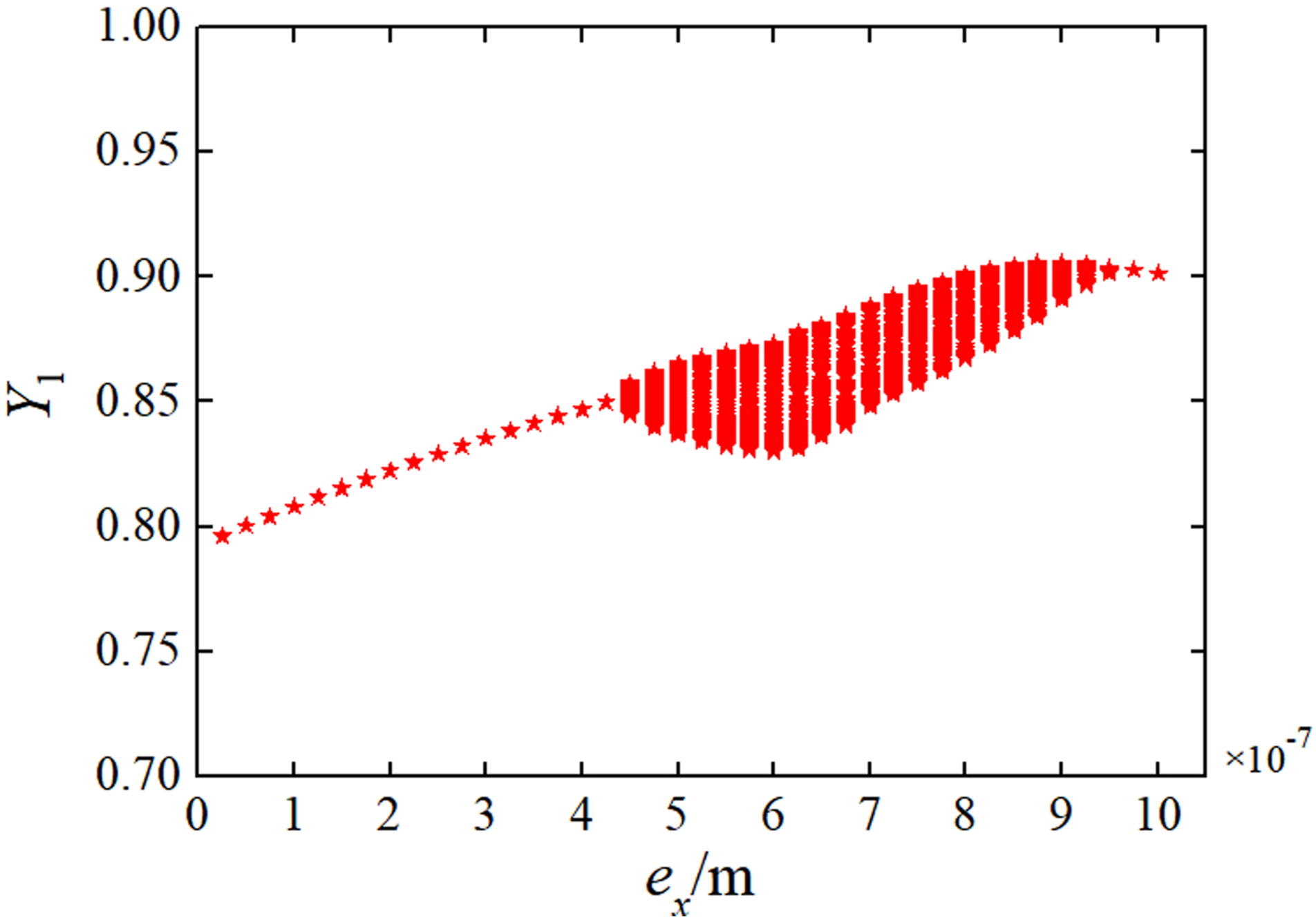
In Figures 14–18, when ω=1000 rad/s, the mass eccentricities e
x
and e
y
are 3×10⁻⁷, 5×10⁻⁷, 7×10⁻⁷, 9×10⁻⁷, and 1×10⁻⁶ m respectively; the dynamic responses of gas-lubricated bearing–rotor system are shown as periodic and quasi-periodic motions. When e
x
=e
y
=3×10⁻⁷ m, the trajectories of periodic motion of journal center are shown in Figure 14(a) and (b), and the Poincaré map has one projection point on the X-Y plane in Figure 14(c). In Figures 15–17, when e
x
=e
y
=5×10⁻⁷, 7×10⁻⁷, and 9×10⁻⁷ m, respectively, the dynamic responses are quasi-periodic motions. Figures 15(a), 16(a), and 17(a) show the trajectories of journal centers at bearing 1 and 2 stations with different eccentricity masses. The projection points of the Poincaré maps on the X-Y plane are torus attractors which are shown in Figures 15(c), 16(d)–(e) and 17(c). Figures 15(d), 16(f) and 17(d) show that the spectrum diagrams are discrete spectrums. Figure 18(a) and (b) show that the quasi-periodic motion bifurcates inversely to periodic motion when e
x
=e
y
=1×10⁻⁶ m. The spectrum diagram contains one spectral component shown in Figure 18(c). When e
x
=e
y
=3×10⁻⁷ m, the periodic motions of journal centers at bearing 1 and 2 stations: (a) Trajectories of journal centers; (b) trajectory of journal center; and (c) spectrum diagram of journal center. When e
x
=e
y
=5×10⁻⁷ m, the quasi-periodic motions of journal centers at bearing 1 and 2 stations: (a) Trajectories of journal centers; (b) trajectory of journal center; (c) Poincaré map of journal center; and (d) spectrum diagram of journal center. When e
x
=e
y
=7×10⁻⁷ m, the quasi-periodic motions of journal centers at bearing 1 and 2 stations: (a) Trajectories of journal centers; (b) trajectory of journal center at bearing 1 station; (c) trajectory of journal center at bearing 2 station; (d) Poincaré map of journal center at bearing 1 station; (e) Poincaré map of journal center at bearing 2 station; and (f) spectrum diagram of journal center. When e
x
=e
y
=9×10⁻⁷ m, the quasi-periodic motions of journal centers at bearing 1 and 2 stations: (a) Trajectories of journal centers; (b) trajectory of journal center; (c) Poincaré map of journal center; and (d) spectrum diagram of journal center. When e
x
=e
y
=1×10⁻⁶ m, the periodic motions of journal centers at bearing 1 and 2 stations: (a) Trajectories of journal centers; (b) trajectory of journal center; and (c) spectrum diagram of journal center.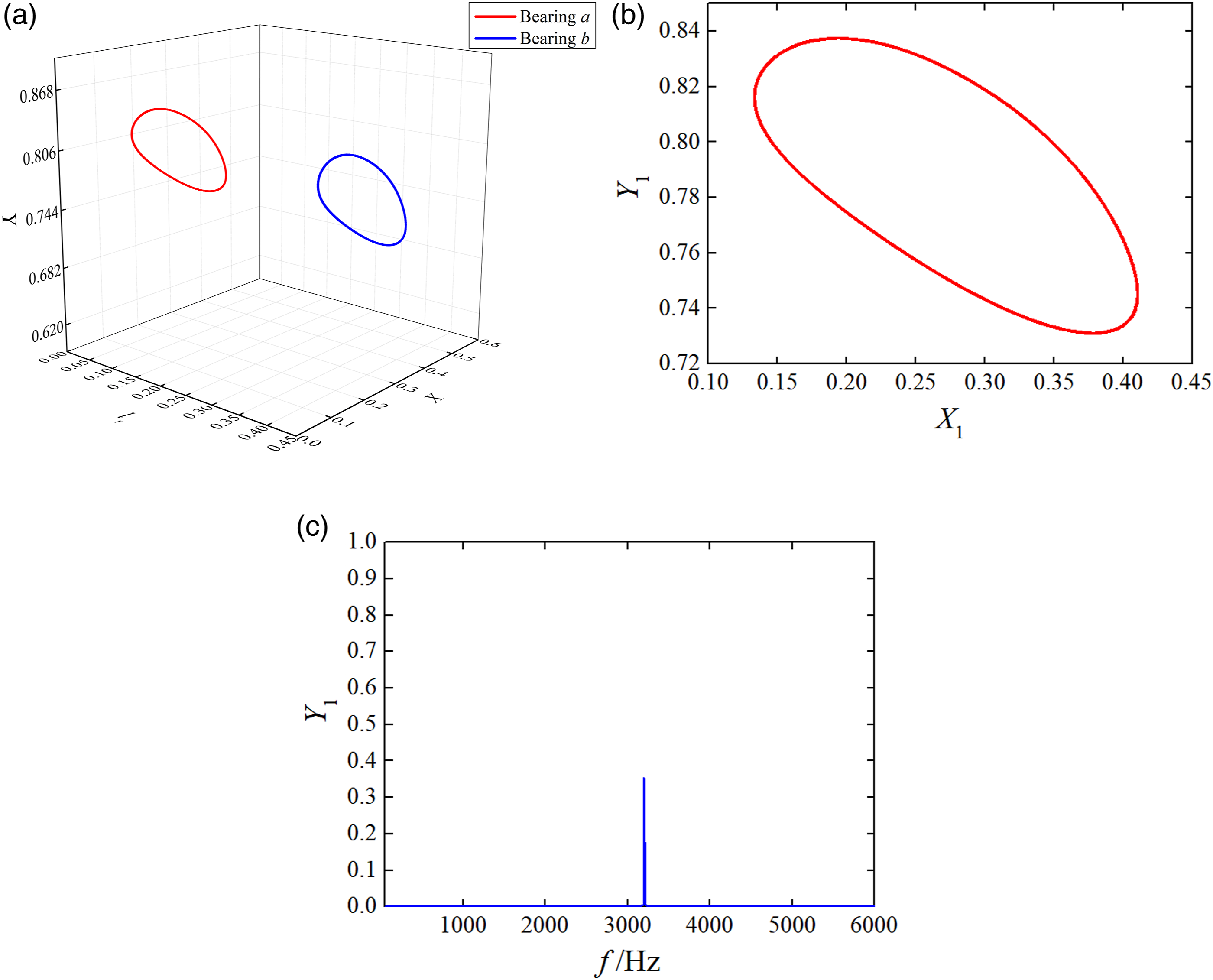
Stability of rotor system
By calculating the subdeterminant of the coefficient matrix of determinant equation, the stability criterions can be obtained. The stability criterions Δ1∼Δ4 are shown in Figure 19(a) and the stability criterions Δ5∼Δ8 are shown in Figure 19(b). The stability criterions Δ1∼Δ4 are greater than 0 for ω=500–5000 rad/s, and the stability criterions Δ5∼Δ8 are greater than 0 for ω=500–3700 rad/s. When ω=3800–5000 rad/s, it can be seen in Figure 19(b), the stability criterions Δ5∼Δ8 are smaller than 0, and the rotor system shows instability. When ω = 500–5000 rad/s, the stability criterions: (a) stability criterions Δ1∼Δ4 and (b) stability criterions Δ5∼Δ8.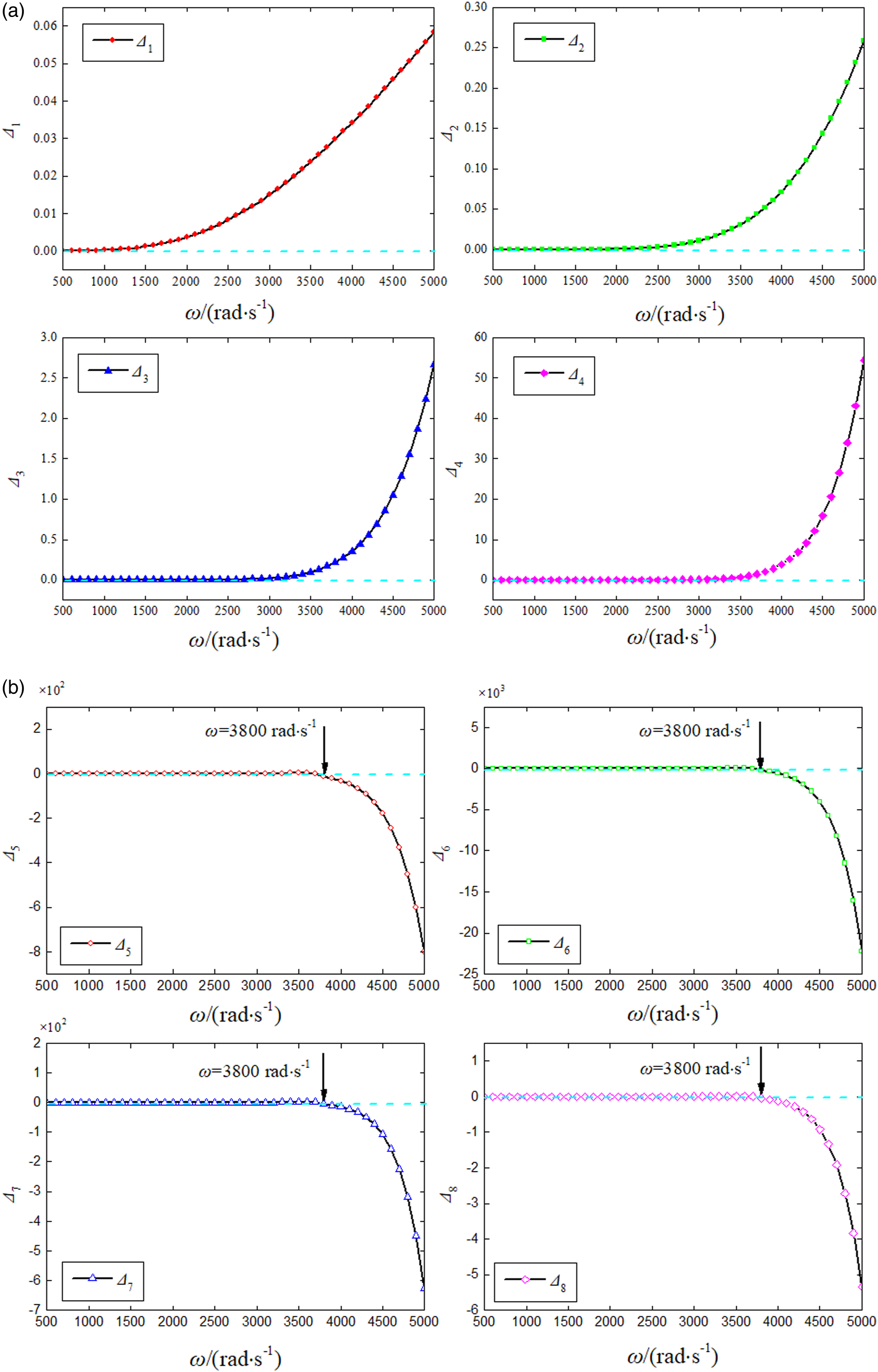
Conclusion
The nonlinear dynamic responses and bifurcation of asymmetric rotor system supported in two axial-grooved gas-lubricated bearings are investigated. A hybrid numerical model is established based on the rational function approximation and motion equation of rotor. The dynamic responses are obtained by solving the proposed model versus different rotating speed, and the computing cost is reduced more than the Newmark-β method. The bifurcation characteristics of gas-lubricated bearing–rotor system are analyzed with the change of the rotating speed and mass eccentricity. 1. The complex number of dynamic stiffness and damping coefficients of the gas-lubricated bearing is approximated as a rational function, which contains a set of rational function coefficients. The rational function coefficients are calculated by the vector fitting method. The rational function model of gas-lubricated bearing is established by using rational function coefficients, which shows the response relationship between nonlinear gas film forces of bearing and motion trajectory of rotor. 2. A hybrid numerical model is established by coupling the rational function model of gas-lubricated bearing with the motion equation of rotor, and the nonlinear dynamic responses of gas-lubricated bearing–rotor system are investigated by solving the proposed hybrid model. The hybrid numerical model avoids the multiple calculations of unsteady Reynolds equation in the dynamics analysis process, and the nonlinear gas film forces can be obtained simultaneously when the responses are solved. The computing cost can be saved. 3. The nonlinear dynamic responses of rotor system supported in gas-lubricated bearings are investigated by trajectory diagrams, Poincare maps, spectrum diagrams, and time series diagrams of the journal centers at bearing 1 and 2 stations. The bifurcation of the nonlinear dynamic response is studied by taking the rotating speed and mass eccentricity as bifurcation parameters. The results show that the unbalance responses of the rotor system have complex dynamic characteristics under different rotating speeds and mass eccentricities. 4. By the Routh–Hurwitz method, the stability of rotor system can be determined by the subdeterminant of the coefficient matrix of determinant equation, and the rotor system shows instability for 3800–5000 rad/s.
Footnotes
Declaration of conflicting interests
The author(s) declared no potential conflicts of interest with respect to the research, authorship, and/or publication of this article.
Funding
The author(s) disclosed receipt of the following financial support for the research, authorship, and/or publication of this article: This work was supported by the National Natural Science Foundation of China (No. 52075438), the Key Research and Development Program of Shaanxi Province of China (No. 2020GY-106), and the Open Project of State Key Laboratory for Manufacturing Systems Engineering (No. sklms2020010).
Appendix 1
The derivation of the relationship between the poles pi of Z(s) and the zeros
According to equations (14), (17), and (20)
The following equation can be deduced because of
Equation (44) shows that the poles p
i
of Z(s) are equal to the zeros
Appendix 2
The coefficients of each order are expressed as follows
The stability criterions are written as