
Abstract
This paper focuses on the steady vibration characteristics of the bladed-disk subjected to the dry friction damping under periodic excitation. The multi-harmonic method and continuation procedure are combined to trace the solution of the nonlinear forced vibration problem. To obtain a stable and fast nonlinear solver, the analytical formulation of Jacobian matrix in frequency-domain is derived for elastic Coulomb friction model with variable normal force. Furthermore, the continuation method is generalized to trace the solution via different parameters, including not only commonly used excitation frequency but also other design parameters of interest. In numerical simulations, a two degrees of freedom system and a lumped parameter bladed-disk model with dry friction dampers are employed to validate the effectiveness and stability of the method. Meanwhile, the effects of damper design parameters on the responses are investigated, especially the effect of normal force is studied to find the optimal solution. The results indicate that the proposed analytical method can provide an accurate quantitative assessment for the optimum design of the bladed-disk dampers.
Introduction
As the turbomachinery turns to higher power, higher rotation speed and larger flow, the blades of machine are subjected to more complex excitations, which makes the vibration mitigation becomes one of the biggest challenges for the blades design.
Friction dampers are widely used in modern steam and gas turbines for the simple structures and effective damping properties. However, due to the strong nonlinearity of the friction dampers including the contact and friction effects, it is difficult to predict the response of the bladed-disks even under a simple periodic excitation. The most widely applied techniques for these nonlinear dynamic problems are perturbation methods1–4 such as Lindstedt-Poincaré method, Krylov-Bogoliubov-Mitropolsky method and multiple scales method. Nevertheless, almost all perturbation methods are based on the small parameters assumption and will result in some limitations of the methods in strong nonlinear systems, especially for large deformation and friction-contact coupled vibration of turbine blade-disks. To overcome the shortcoming of small parameters assumption in strong nonlinear systems, some novel analytical methods have been proposed in last two decades5–14 such as the harmonic balance method (HBM), the homotopy perturbation method, a domain decomposition method, the variational iteration method and the energy-balance method. All these methods have been proved to be effective techniques in some nonlinear systems for large parameters.
The HBM, also known as Fourier-Galerkin method, has been thought as a robust and effective method to analyze the steady-state response of the strong nonlinear system in recently works. This method approximates the unknown periodic displacements with their Fourier coefficients. Then the nonlinear force, which is a function of displacement, velocity and acceleration, can also be expanded as Fourier form by the same number of harmonics analytically. The advantage of this method is that it can transform nonlinear problems from full time-domain into reduced frequency-domain, which implies less unknowns in the harmonic balance method. Meanwhile sufficient accuracy of the steady-state solutions can be achieved with few harmonic numbers for most nonlinear problems. For these reasons, HBM has received increased attention for the last couple of years.
In early works, mono-HBM,15–17 a special form of HBM, also called approximate linear model was adopted, where the friction dampers are linearized to simplify stiffness and damping coefficients during the period time. Wu and Yuan18–20 extended this method to a practical approach for design of blade dampers in industry. However, too few harmonics in approximation has been proved to result in low accuracy near resonance frequencies. Hence, more harmonic numbers must be considered and related researches can be found in literature.8,9,21,22 It is noticed that the robustness and efficiency of a Newton-based iterative solver for HBM nonlinear equations is determined by the accuracy of the Jacobian matrix in the frequency-domain, which can be expressed as the derivative matrix of harmonic coefficients of nonlinear force respected to that of displacement. In previous studies, the Jacobian matrix for nonlinear force, especially for friction and contact forces, is calculated numerically or approximately, resulting in difficulty of convergence or even failure in some special regions. Therefore, it is necessary to derive the analytical formulation of the Jacobian matrix for the friction force in frequency-domain.
On the other hand, the mathematical model of the dry friction force is crucial for the accuracy and reliability of the results. Primary friction models can be divided into two primary categories: those based on Coulomb approach and those established on the bristle analogy. The classical models, 23 such as Dahl, LuGre, stick–slip model, elastoplastic model and the Gonthier model, are widespread engineering friction models. However, it should be emphasized that each model has its own unique parameters and scope of application. In recent years, some new mathematical models24–26 for the description of micro-hysteresis, based on fractal theory, have also been developed for practical applications. It is worth mentioning that Hai-Yan Kong’s friction law provides a simple and effective calculation method based on fractal dimension. 27 Meanwhile, due to the precision improvement of numerical methods, experimental investigations28–30 of friction parameters have also reached a very high level of accuracy. In the study of vibration for bladed-disk systems, the elastic Coulomb friction model is adopted as an approximate model, in which both the computational efficiency and accuracy are considered.31,32
Strictly speaking, the normal force between friction interfaces is non-constant because of vibration and gas-flow impact. When the normal displacement is too large, the contact surfaces can even result in separation during the vibration cycle. The tangential friction performance will be completely different from that of constant normal force model. Yang et al. 33 developed the elastic Coulomb friction model considering contact and separation state of normal directions theoretically and investigated the vibration characteristics of a one-dimension system by mono-harmonic method. This mono-harmonic method was further extended to multi-harmonic method by Petrov and Ewins analytically. 34 Furthermore, the method was generalization in finite element analysis for high-fidelity bladed-disk.35,36
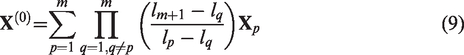
In realistic design practice, there is usually a need to choose sets of parameters of interest that can provide minimum forced response or satisfy other requirements. Moreover, all the parameters of the bladed-disk design problem are subjected to some variations due to operating condition changes. For instance, there exists an optimal normal force on friction interface that can reduce the vibration level under gas-flow excitation condition. But, it is problematical to know how the vibration amplitude varies at some dangerous frequencies in the vicinity of the designed optimal value? And it seems impossible to obtain the variation through a large amount amplitude-frequency response curves. Therefore, the continuation procedure corresponding to excitation frequency should be generalized to an arbitrary parameter, which requires that the derivative forms of solutions with respect to these parameters be derived analytically, especially for multi-harmonic coefficients in frequency-domain.
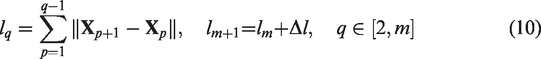
In this paper, the multi-HBM in the frequency-domain is applied to solve the nonlinear forced vibration problem under period excitation, which allows the displacement and the force to be represented by sufficient harmonic components. Several continuation algorithms are employed to trace the solution of the nonlinear equation via different parameters, including not only commonly used excitation frequency but also some design parameters of interest.
To describe the contact and friction states of the dampers more accurately, one-dimension elastic Coulomb friction model is generalized to consider variable normal force or separation state. In order to obtain a stable and fast nonlinear solver for the multi-harmonic equation established above, a concise analytical formulation instead of the finite differential method in frequency-domain is derived in this paper, which includes the Jacobian matrix for nonlinear equations and the derivative vectors with respect to design parameters.
A two degrees of freedom system with dry friction damper is used to demonstrate the effectiveness and stability of proposed method. The result shows enough precision of this method compared with the time marching methods (TMMs). The effects of several parameters on the responses such as excitation level, stiffness coefficient of friction model and two components of normal force are investigated. At last, in order to investigate the optimal design of normal force between the shrouds of blade-disk, a lumped parameter model is applied to simulate a complex bladed-disk system with both root-disk and shroud-shroud dampers. The effects of normal force design value and its fluctuations on the forced response of bladed-disk are discussed.
Multi-harmonic balance equation
The dynamic equation of a bladed-disk system under forced excitations and nonlinear interactions can be written in the form

Then all the time variation vectors such as displacements

For multi-harmonic equations (N is the total number of harmonics), the frequencies of the harmonic components can be expressed as kω (satisfies T = 2π/ω). Let

The –kth harmonic coefficient in equation (3) [

While the velocities and accelerations vectors can be expressed as functions of the vector
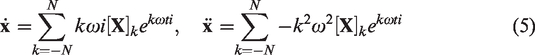
In accordance with the multi-HBM, the expansion from equations (2) and (5) are substituted into the motion equation (1). As a result, the time-domain equation (1) is transformed to the multi-harmonic balance equation in frequency-domain with respect to the solution vector


Continuation procedure
Classical Newton-Raphson method is usually adopted to solve equation (6). However, it always causes difficulty in convergence at resonance frequency points or even fail at turning points and bifurcation points. In order to enhance the stability of the nonlinear solver, it is of interest to trace the loci of the solutions by introducing a continuation parameter λ as shown in equation (8), rather than solving at only one single value of parameter. For example, the parameter λ can be chosen as the frequency of excitation frequency ω, the level of excitation force, or the nonlinear force parameter.

The predicator-corrector technique is used in the sequential continuation procedure with the variation of parameter λ. The first step is the predictor, which is also called solution initialization, for speeding up the iterative convergence at a given step of the procedure. Tangent and secant predicators
22
based on pre-converged solutions are thus used to initialize
The second step is the corrector, which is calculated using the iterative Newton-Raphson algorithm in this paper. The iterative process can be performed by incremental form of equation (8).


The iterations are stopped when a prescribed accuracy
Analytical formulation of nonlinear derivative terms
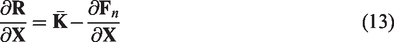
It should be noted that the Jacobian matrix and the derivative vector with respect to λ in equation (11) are required to be updated in every Newton-Raphson iteration. In some problems, the analytical expression of Jacobian matrix is too complex to be obtained or some calculations of the whole matrices require large computational cost. So there is a compromise way to calculate these terms numerically using finite differences with a perturbation, which was utilized in several previous works. However, it turned out that these methods of difference cannot provide a reliable convergence, especially for strongly nonlinear problems. These nonlinear derivative terms are derived by general formulations in this section.
First, the Jacobian matrix
In order to compute the derivatives of Force Fourier coefficients [


The continuation procedure allows solutions of a nonlinear equation to be traced when the parameter λ varied. There are different choices for λ to follow the solution curves under parameters variation, and three patterns as follows are discussed in this paper.
When λ is the frequency of excitation frequency, i.e. λ = ω, the expression of the derivative vector takes this form

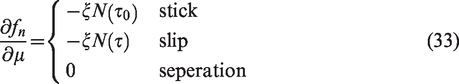
The j-th block of the vector can be calculated by Fourier transformation
2. When λ is a parameter of the nonlinear force vectors


Then nonlinear force 3. When λ is a parameter of modifications of linear components, i.e. λ=q, for example, q can be the design parameters of the stiffness, mass, linear damping matrices or the parameters of excitation levels.
It should be illustrated that all the nonlinear derivative terms in the numerical calculation only need to be computed on the nonlinear DOFs. For contact or dry friction problems, the vector
Dry friction model
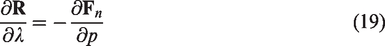
The nonlinear restoring force between the contacting surfaces of a bladed-disk system, such as root-disk joints and shrouds contacts, is usually modeled by one-dimension elastic Coulomb friction model
11
as shown in Figure 1(a). The friction force can be expressed as a unified form


The elastic Coulomb friction model with variable normal force. (a) Contact and friction interface model and (b) Contact and friction states transition.
Due to the vibration or excitation of dampers, the normal force N(τ) is inevitably non-constant in practical bladed-disks. For example, two patterns of hysteresis loop curve with variable normal force are exhibited in Figure 1(b), where the left part depicts the DOF in contact during the vibration period and the right part shows a case where separation occurs.
Considering equation (23), the friction force can be calculated by a semi-explicit form
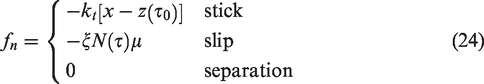
However, it should be emphasized that the term z(τ0) in equation (24) is still implicit and history-dependent for stick state. Therefore, nonlinear force fn depends on not only the relative displacement x but also an implicit variable z(τ0). The component of Jacobian matrix for the nonlinear DOF in equation (14) should be modified as

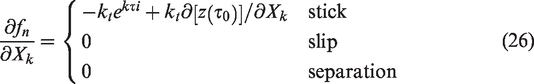
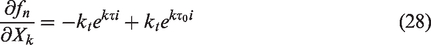
Therefore, only the term of stick state in equation (26) should be considered. It is evident that stick state can be transformed from two states (slip and separation). The first case is the separation to stick transition. Then the friction force at the beginning of stick state has to be equal to the value of the force at the end of separation in order to be continuous over a period, which means that z(τ0) should satisfied equation (27).

Substituting equation (27) into equation (26), we obtain
The second case is the slip to stick transition, still considering the continuity condition of the friction force

Then derivative term for stick state comes into

Also note the differential of equation (29), in other words, the continuity equation of the velocity is

It is interesting that the same form can be obtained as equation (28) when equation (31) is substituted into equation (30), which indicates that the Jacobian matrix can be calculated only by the stick transition time over the period.
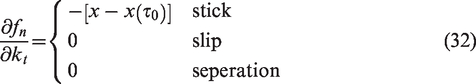
Similar to the above derivation process, When p is the stiffness coefficient When p is the friction coefficient When p is a harmonic coefficient of normal force
All these analytical integrals derived above, involving transformations between time domain to frequency domain, can be calculated by Fast Fourier Transform, which provides an efficient and exact calculation technique in numerical analysis.
Numerical studies
A two degrees of freedom model with dry friction damper
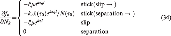
First, a two degrees of freedom system with a dry friction nonlinearity, as shown in Figure 2, is considered with k1 = 4π2, k2 = 2π2, c1 = 0.5, c2 = 0.5, m1 = 1 and m2 = 1. A nonlinearity friction damper located DOF 2 is considered here with default parameters kt=30, μ = 0.3. The excitation force and the normal force for this test is expressed as
Oscillator with two degrees of freedom with a friction damper.
For all calculations, total harmonic number N = 11 is considered and the condition R < 10−9 is used as convergence criteria for iteration process. The forced responses of maximum displacement and harmonic spectrum at DOF 2 with f0=100 N N0=100 N and N1=200 N are shown in Figure 3. Two special cases of the linear system are also plotted in this figure: first is the full-stuck of the friction damper DOF and second is the frictionless of this DOF. A closer look at the low frequency region reveals that the super-harmonic resonances keep at a higher level than first main harmonic, which clearly shows the necessity of multi-harmonic expansion.
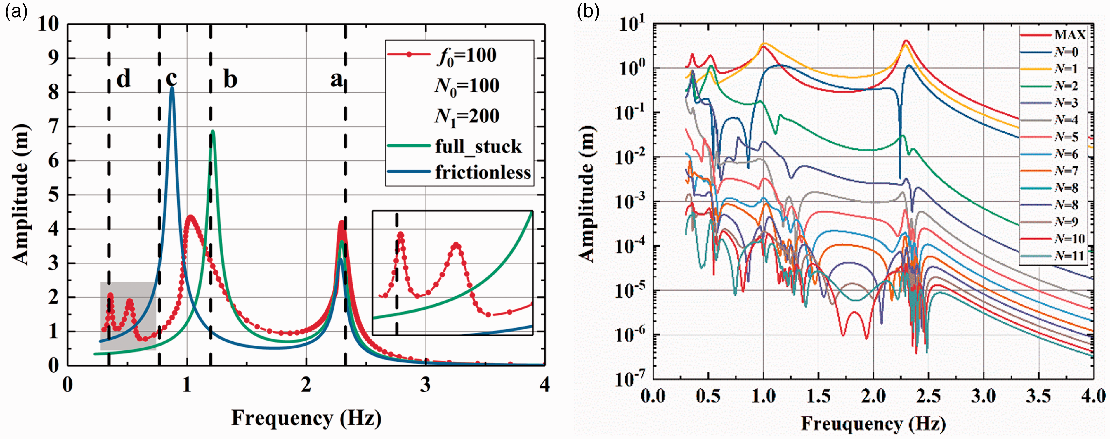
Frequency-domain response results of DOF 2. (a) Frequency-domain forced response and (b) Amplitudes of harmonic components.
Furthermore, the comparisons between the multi-HBM and the TMM (Newmark method applied in this paper) at a, b, c and d points are presented in Figure 4 to validate the proposed method. The time-domain response curves and Hysteresis loops both show that the calculation results with two methods are agreed very well in these 4 points, while the points c and d show significant different harmonic components in two vibration periods. The existence of super-harmonic resonances at frequency 0.769 Hz and 0.346 Hz can be seen obviously in the time-domain curves as shown in Figure 4, it can also be observed in the harmonic spectrum that second and third harmonics are even higher than the first harmonic at low excitation frequency.
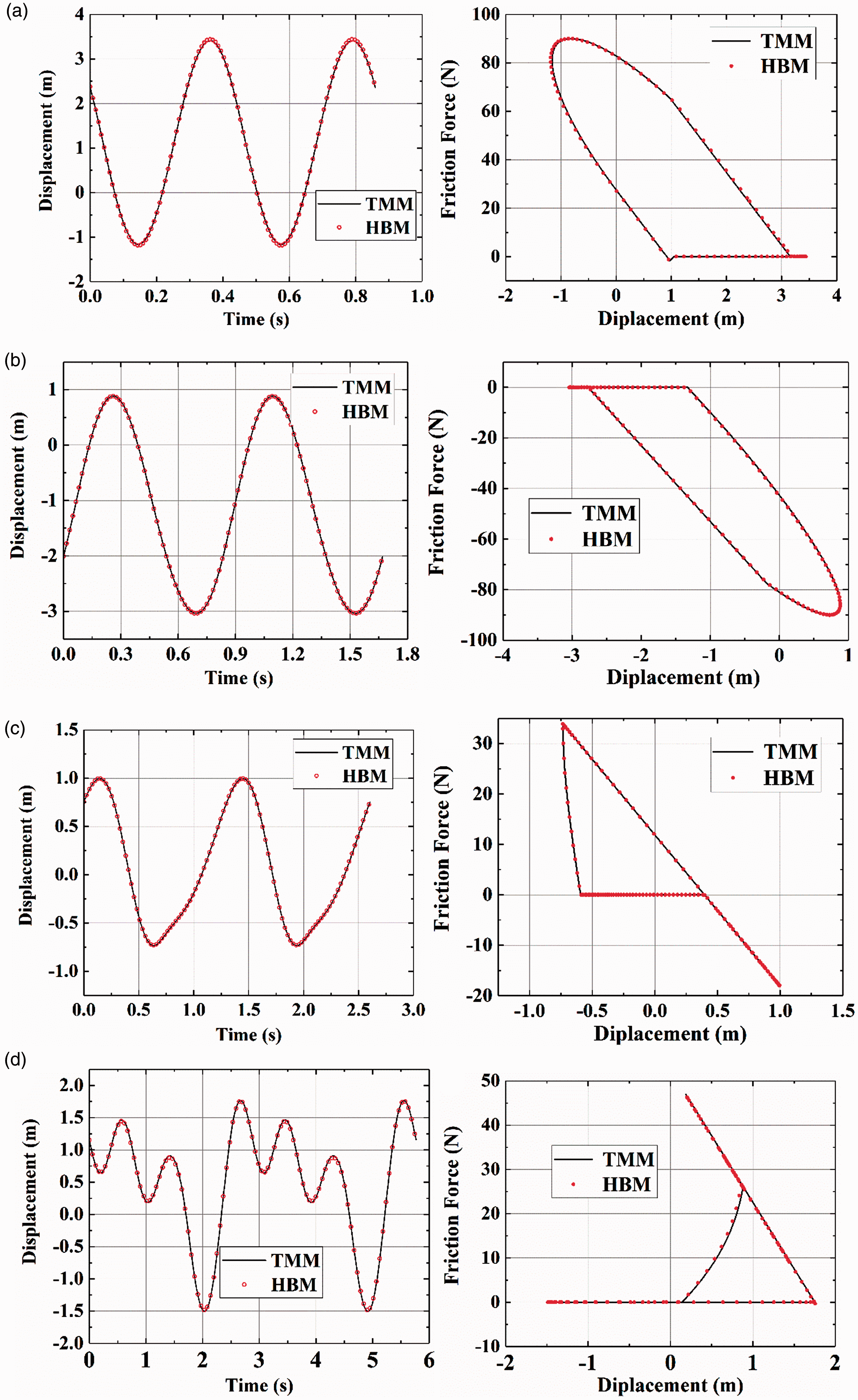
Comparison of results by multi-HBM and TMM. Time-domain response curves and hysteresis loops at frequency (a) 2.328 Hz, (b) 1.198 Hz, (c) 0.769 Hz and (d) 0.346 Hz. TMM: time marching methods; HBM: harmonic balance method.
It is worth noting that the hysteresis loop of the friction DOF shows essentially different form from a general form of friction model with constant normal force, which is a parallelogram. The separation state can be identified by friction force with zero value constantly, and the stick state can be marked easily if the force and relative displacement are linear. When the friction damper keeps slip state, the hysteresis loop is usually a curve due to the valid normal force.
Next, the effects of different parameters on the vibration characteristics of this oscillator are discussed. Four cases are considered as follows in this numerical test.
Excitation levels f0
The forced response amplitude with respect to excitation levels is investigated with N0=100, N1=30 in equation (35). The forced response in frequency-domain is presented in Figure 5 with different excitation levels
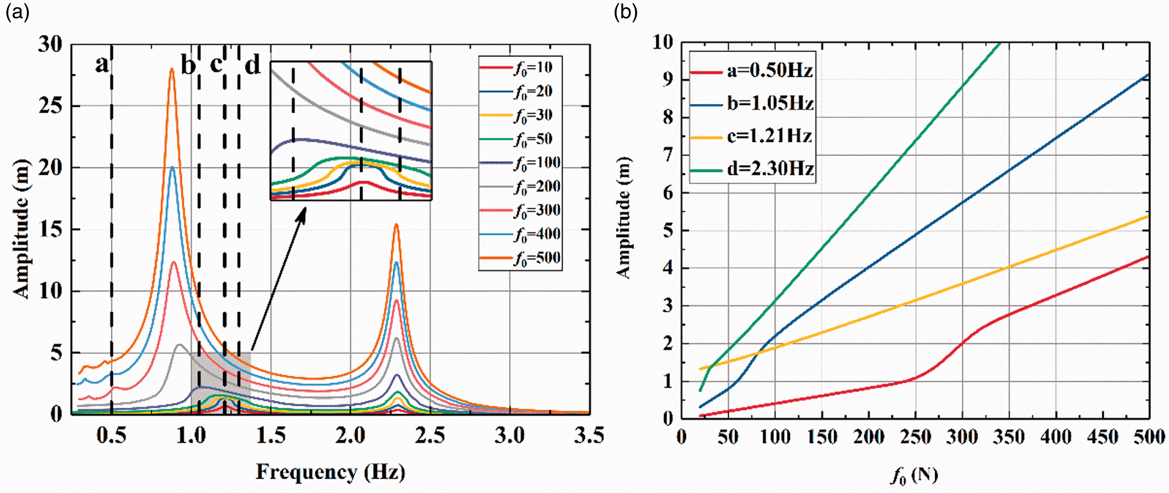
Effect of excitation level f0 on frequency responses. (a) Frequency-domain forced response and (b) Forced response at a, b, c and d frequency.
It can be obtained from Figure 5(a) that major resonance frequency decreases gradually with the increase of excitation level. At low excitation level (f0 < 20 N), the resonance frequency which remains unchanged equals to that of the underlying linear system. When the excitation increases to a certain extent that it can activate the nonlinearity, i.e. introduce some slipping into the friction DOF, the resonance frequency will be closed to frictionless linear model. As a consequence, the resonance frequency gradually shifts from the linear full-stuck model toward the linear frictionless model.
Meanwhile, the force response at point a, b, c and d with respect to excitation level can be solved as shown in Figure 5 by selecting λ as the excitation level f0. Due to the effect of dry friction damper, the response amplitude is not linearly depending on the excitation level.
Tangential stiffness kt
In the same way, the response amplitude corresponding to some parameters of the friction model can be obtained, for example, tangential stiffness kt. As shown in Figure 6, the resonance frequency increases with tangential stiffness kt when all other parameters are fixed, but the resonance peak gradually decreases or even completely suppressed. However, it is usually difficult to determine the tangential stiffness of the friction surface accurately in practical designs. The above analysis can only provide qualitative conclusions.
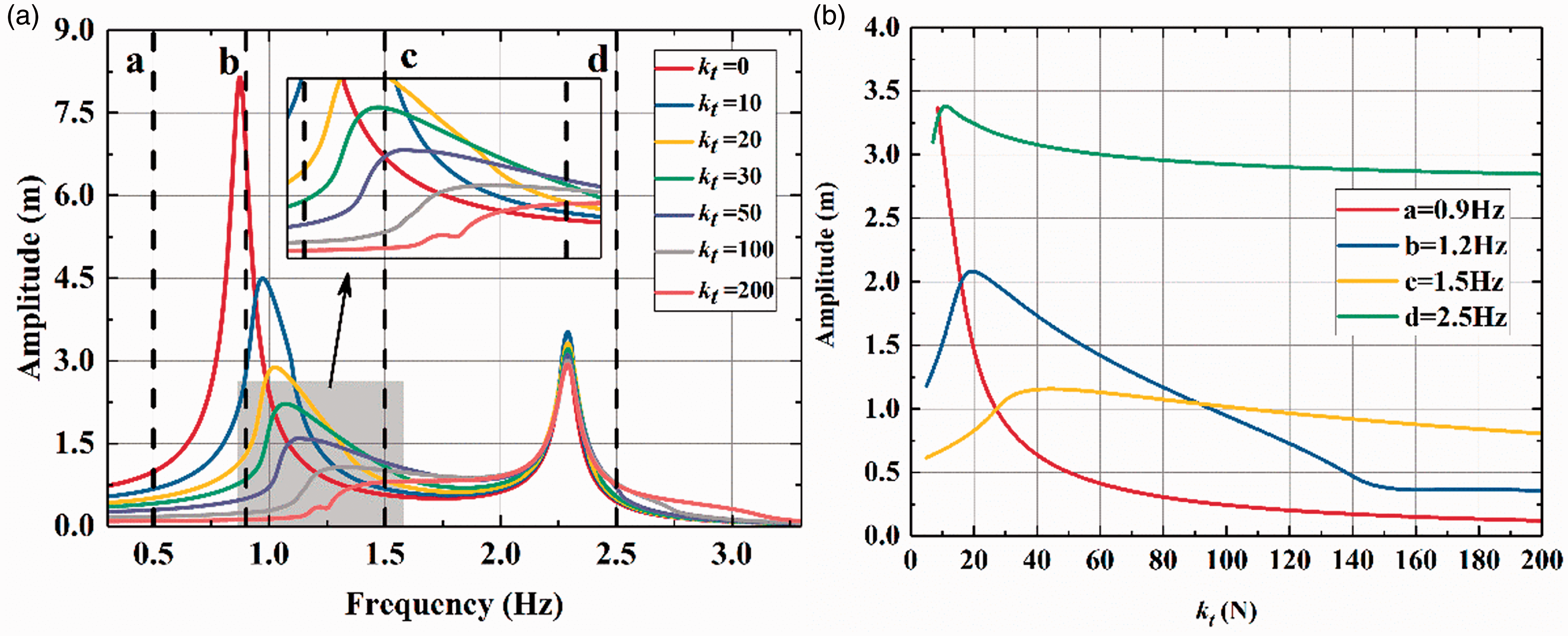
Effect of tangential stiffness kt on frequency responses. (a) Frequency-domain forced response and (b) Forced response at a, b, c and d frequency.
Normal force N0
The optimal value of normal force is a key part in design of friction dampers. That is, the constant component N0 of normal force for minimal vibration response in this case. Let the value of N0 varies from 10 to 500 and N1 is set as 0.3 N0. The frequency response curve is shown in Figure 6, where the two black curves are two linear systems with stuck damper and frictionless damper, respectively. Similar to the increasement in excitation force, it shows that the resonance frequency does not vary with a large normal force, which can be also explained by the system that is equivalent to the linear system with damper in full-stuck state. When the normal force is not large enough to maintain the friction state in full-stuck, the damper comes into stick-slip transition states and the system will approach to the linear system with frictionless damper. It is shown that an optimal load is found when normal force reaches 100 N (dotted line), which results in a minimum forced response amplitude at the blade tip. An accurate quantitative relationship between the amplitude at each frequency point as shown in Figure 7 (a, b, c and d) with different N0 can be obtained, providing a reference for optimization of normal force with regard to vibration mitigation.
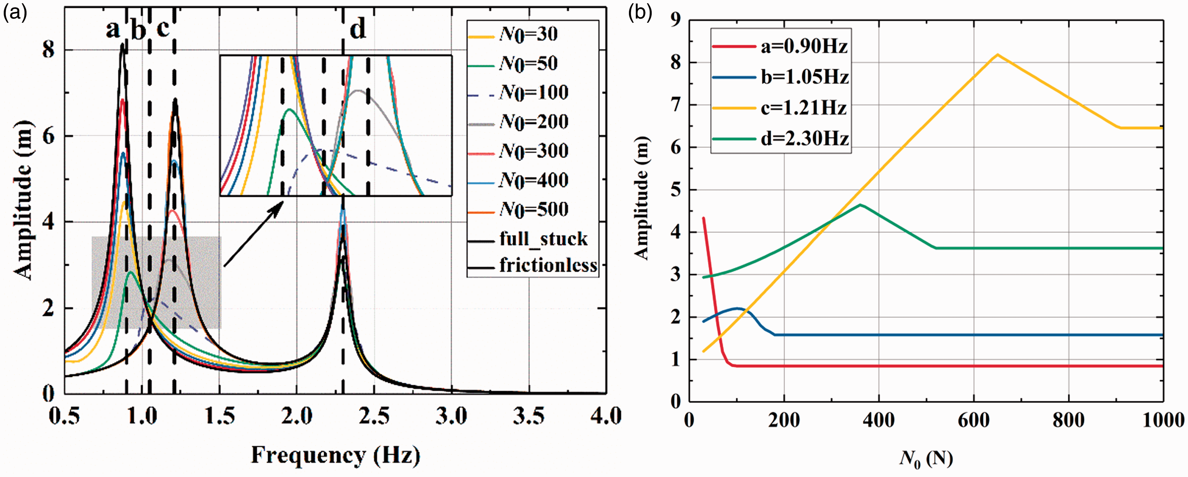
Effect of normal force N0 on frequency responses.(a) Frequency-domain forced response and (b) Forced response at a, b, c and d frequency.
Normal force fluctuation N1
When the normal force N0 keeps an optimal value, the vibration characteristic is studied under different fluctuation components N1 caused by excitation or other periodic changes of working conditions. The normal force fluctuation N1 is set from 0 to 500 N with N0=100 N. It can be observed from the frequency response curve shown in Figure 8 that fluctuation components have little effect on the resonance frequency when N1 keeps a small value. However, a large fluctuation will result in greater amplitude especially when N1 > 50 N, while the increasement will slow down or even decrease as the fluctuation increases. Another interesting phenomenon is that when N1 exceeds N0, that is, the friction damper occurs separated, then super-harmonic responses will appear.
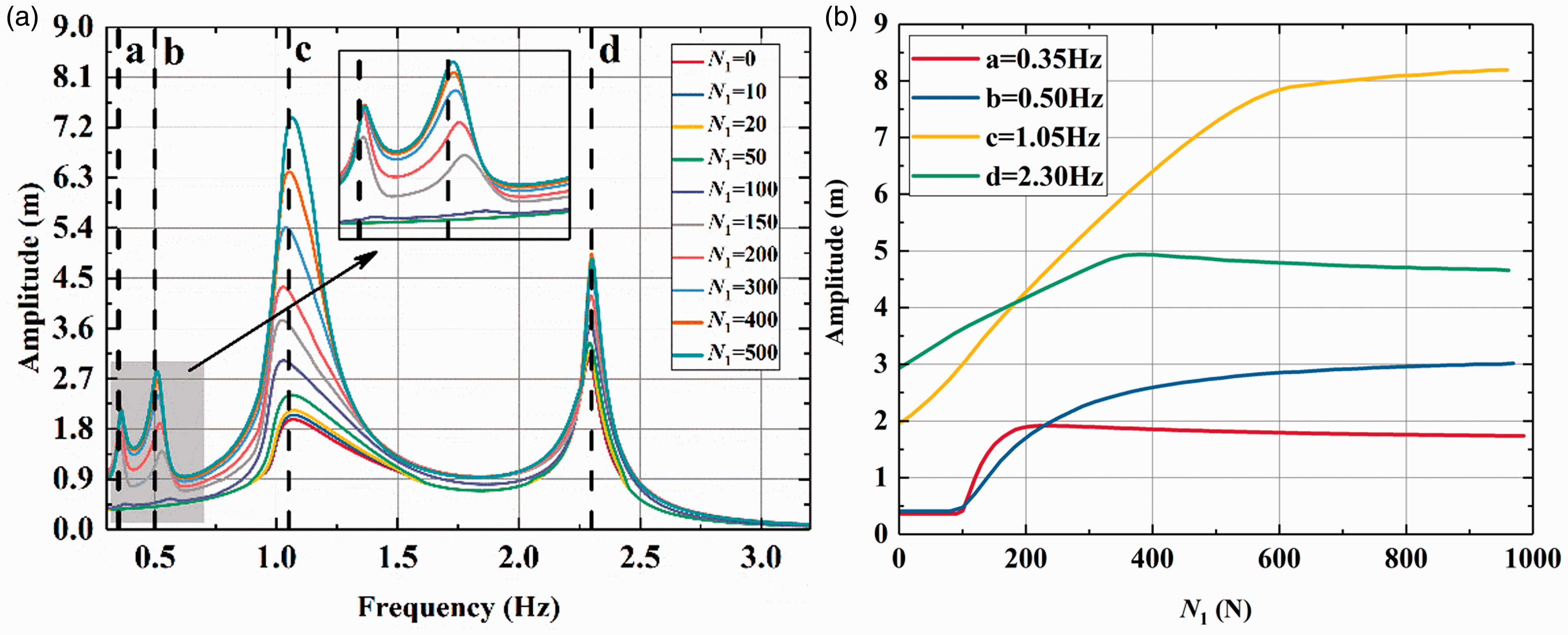
Effect of normal force fluctuation N1 on frequency responses. (a) Frequency-domain forced response and (b) Forced response at a, b, c and d frequency.
A lumped parameter model for a bladed-disk system
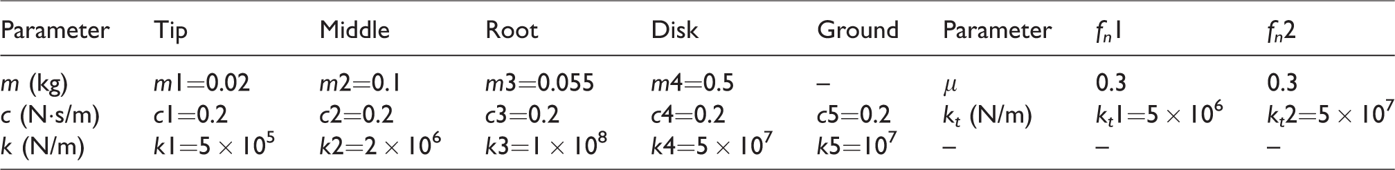
A lumped parameter model (LPM) as shown in Figure 9 simulating the bladed-disk model with high fidelity has been devised to explore complicated phenomena of a bladed-disk system. A total number of eight sectors are retained in this example, and each symmetric sector including the blade tip, middle, root and disk is simplified as 4 DOFs. The response of blade tips is mainly focal point in the bladed-disk. Two adjacent sectors are coupled by the disk DOFs, and the stiffness and damping of ground are both introduced to the boundary condition of system. Based on actual dimensions and material properties of bladed-disk, all the calculated values of mass, stiffness and damping in each section are summarized in Table 1.
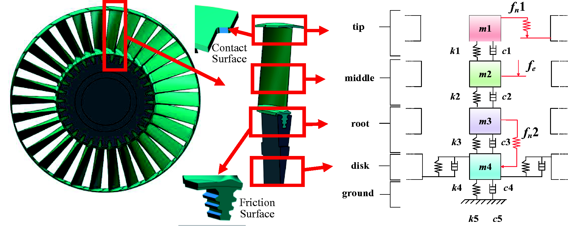
LPM for a bladed-disk with two dry friction dampers.
Parameters values of LPM.
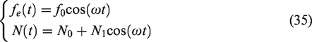
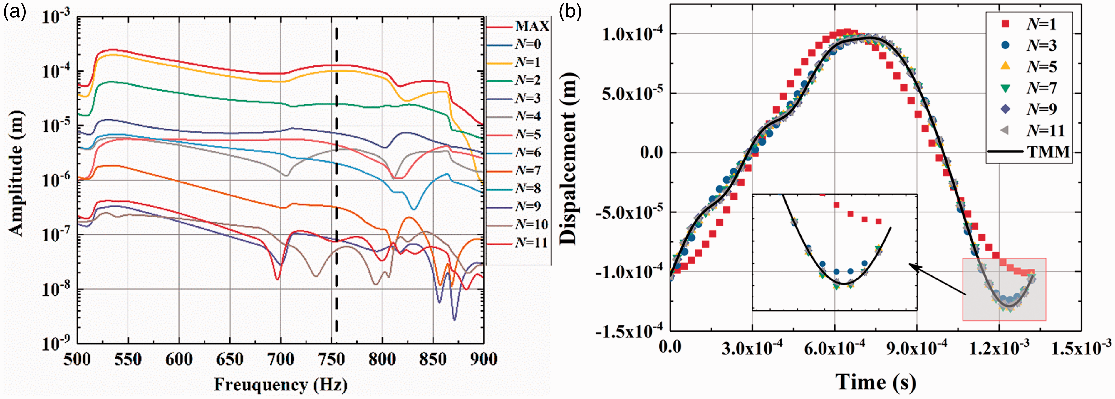
In a turbomachine, the gas exciting force, which is the major external excitation for considered system, can be calculated as a circular periodic excitation simply. Therefore, the excitation fe(t) can be described as a cosine traveling wave with i nodal diameters as equation (36), acting on the blade middle DOF, where f0 is the excitation level coefficient, Nb is the total blade number and j is the index of blade.
Two dry friction force interfaces are considered in this study. The first one is between blade and disk interface, and the second is between two adjacent shrouds. The values of friction parameters are shown in Table 1. It should be indicated that normal force of blade-disk is mainly provided by the centrifugal force of blade, which can be regarded as a constant value during the period time. However, the contact and friction force between shrouds have obvious fluctuations or even separation in one cycle. The optimal normal force is especially important in the damper design. The influence of normal force N(t) between shrouds on system vibration is discussed as follows. Similar to excitation force, N(t) is also expressed as a traveling wave as equation (37)
The natural frequencies in the first family modes for this symmetric bladed-disk are still considered for two special linear cases as above: full-stuck and frictionless interfaces of the shroud dampers. The first frequency family of the frictionless system distributes in the range of 575 Hz–587 Hz, while first-order nodal diameters frequencies are between 755 Hz and 785 Hz for the full-stuck system. The frequency range considered (500 Hz–900 Hz) for the forced response includes a major resonance at first-order nodal diameters.
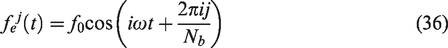
A sufficient number of harmonics (N = 11) are kept to account for the stick–slip-separation transitions occurring at the interface when the nonlinearity is activated. It can be noted from Figure 10(b) that as harmonic number N rise from 1 to 11, the response curves can converge to the solution by TMM gradually. It should be pointed out that, as shown in Figure 10(a), the response of super-harmonics in the entire frequency model is not negligible and the mono-harmonic method (N = 1), which is widely used in engineering design, has obvious limitations.
Forced response of the blade tip (f0 =50 N, N0=200 N, N1=400 N). (a) Amplitudes of harmonic components and (b) Time-domain response at frequency 755 Hz. TMM: time marching method.
Next the vibration characteristics of the LPM bladed-disk under normal force design value N0 and its fluctuation N1 of the shroud surfaces are discussed.
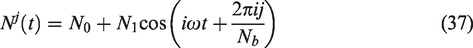
The excitation amplitude value f0 in equation (36) is fixed as 50 N, with an excitation on each blade middle m2 as shown in Figure 11. In the first case, different normal force values N0 (80 N to 3000 N) are set as the contact load between shroud-shroud surfaces. As expected, there exists an optimal load about 200 N, which leads to a minimum of forced response of the blade tips. The effect of damping is significant that the resonance peak of the bladed-disk with the normal force of 200 N is 0.103 mm. As analyzed above for the 2-DOFs system, the resonance frequencies share the same value (755 Hz) for the shrouds dampers at a high normal force and the full-stuck linear system. Once the normal force is below 90 N, which means the friction interfaces will introduce more slipping, the resonance frequency will be close to frictionless linear system (575 Hz). Meanwhile, the amplitude will increase sharply at the resonance frequency.
Forced response curves under different normal force N0. (a) Frequency-domain forced response and (b) Forced response at a, b, c and d frequency.
Moreover, it can be obtained that the vibration amplitude is insensitive to the constant component N0 of normal force in the range of 100 N–1000 N; however, the resonance frequency range will significantly reduce with little amplitude increase, which means a safer vibration performance of the system at N0=500 N in this frequency range. As the N0 further increases, one can observe that the amplitude increases slowly and the resonance frequency range does not change much. As a consequence, a tighter design of shrouds than optimal normal force value is more conducive to vibration mitigation.
The effects of fluctuation component of normal force at N0=200 N are also investigated with the fluctuation N1 varying from 0 to 500 N. It should be noticed that the friction damper DOFs will appear separation during the periodic time when N 1>N0. When the fluctuation N1 keeps a small level, as observed in Figure 12, the maximum amplitude in the frequency interval increases slowly with N1. Besides, it can be noticed that the forced response is insensitive to normal force fluctuation when N1<N0.
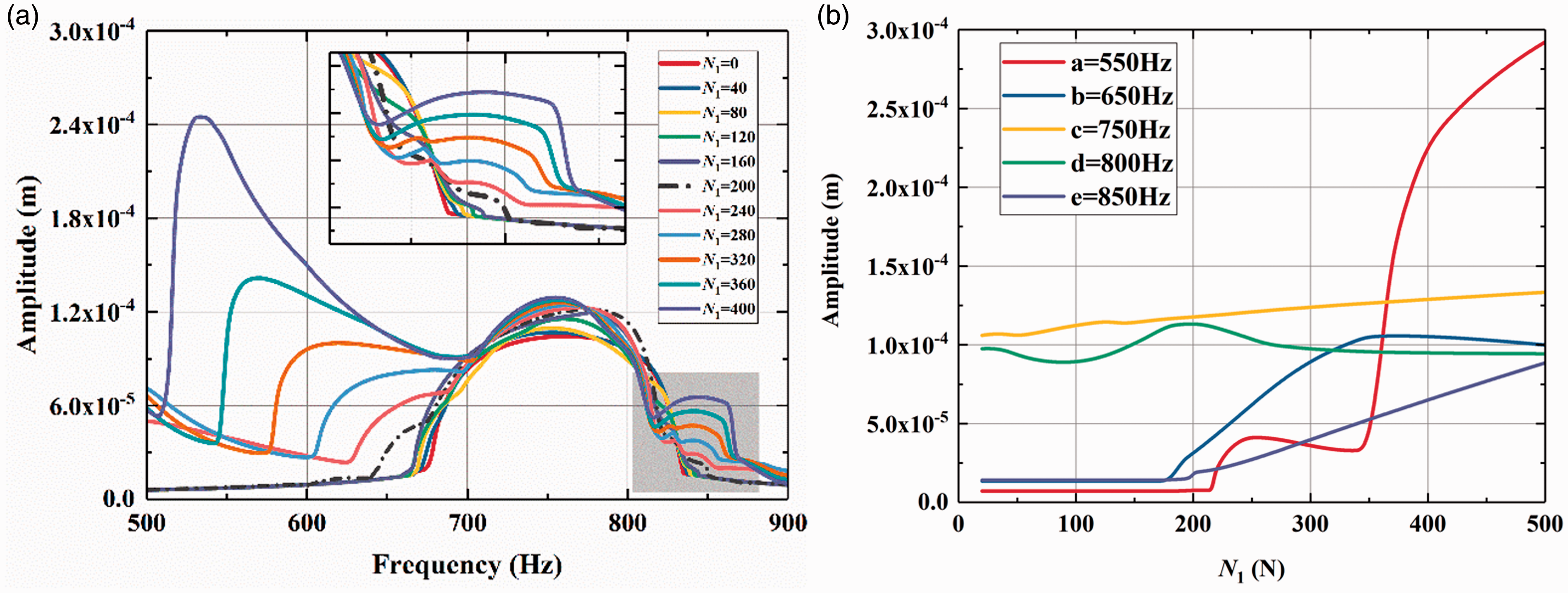
Forced response curves under different normal force fluctuations N1. (a) Frequency-domain forced response and (b) Forced response at a, b, c and d frequency.
As N1 increases above N0, which means the adjacent shrouds occur separated, one can observe completely different forms of response curve. Three peaks can be found in the frequency range, one of which is same as that with no separation of shrouds at 755 Hz. The remaining two resonance peaks are located at 750 Hz, the resonance peaks at lower frequency increase significantly with the increase of fluctuation value. Furthermore, a more elaborate analysis of the response amplitude at different frequencies corresponding to the normal force N0 and N1 is given in Figure 12(b).
To explore the effects of both frequency and normal force, the cloud maps, as shown in Figure 13, exhibit the relationship between the vibration amplitude and the excitation frequency, as well as positive pressure of these two variables. The blue curve shows the maximum response amplitude and the normal force in the frequency interval. For normal force N1, the sharp increase in response to a small normal force can be observed clearly in the graph, however, the amplitude changes slightly when the normal force increases. Therefore, special attention should be paid to the resonance frequency interval in this situation. The dangerous resonant region is significantly reduced, while the amplitude increase is not obvious even if the normal force increases to a large extent. The optimal normal force requires two indicators: risk range of resonance frequency and the maximum response amplitude. As a consequence, this analysis method can not only predict the optimal normal force accurately but also evaluate its sensitivity in frequency-domain.
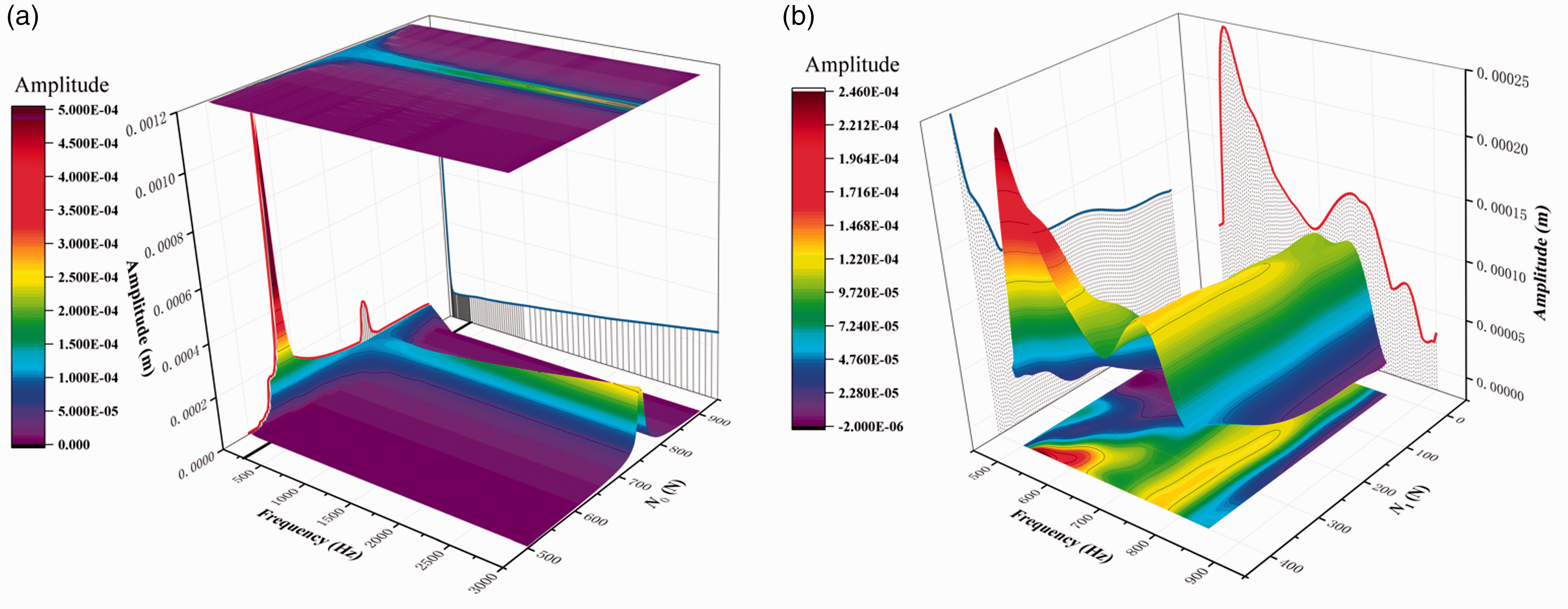
Dependency of frequency-domain response level on different normal forces. (a) Response level with respect to normal force N0 and (b) Response level with respect to normal force N1.
Figure 13(b) reveals a worse effect of friction damping with fluctuation value increase of normal force. Both the resonance frequency range and the response amplitude will expand when N1 is greater than N0. Meanwhile, due to the expansion of the separation-states, the resonance peak will move to a lower frequency. Different from the phenomenon of more slip-states, resonance frequency is even lower than that of the natural first-order nodal diameter, which is closer to the first-order nodal circle (507 Hz) in slip-states of dampers. The results indicate that separation-states of the shrouds should be avoided in the design of the bladed-disk.
Conclusions
This paper focuses on the vibration characteristics of the bladed-disk subjected to the dry friction damping under periodic excitation. The multi-harmonic method in frequency-domain and continuation procedure is combined to trace the solution of the nonlinear forced vibration problem. In order to obtain a stable and fast nonlinear solver, a concise analytical formulation of Jacobian matrix for elastic Coulomb friction model with variable normal force is derived. Furthermore, the continuation method is generalized to trace the solution of the nonlinear equation through different parameters, including not only commonly used excitation frequency but also other design parameters of interest, such as the norm loads and the material properties.
In the numerical analysis, a two degrees of freedom system with a dry friction damper is used to demonstrate the effectiveness of the proposed method, which shows higher precision compared with the approximate linear model widely applied in engineering design. Meanwhile, the effects of several parameters on the response such as excitation level, elastic stiffness coefficient of friction model and two components of normal force are investigated. Finally, a lumped parameter model for a bladed-disk with both root-disk and shroud-shroud friction dampers is employed to investigate the optimal design of normal force. The proposed analysis method can provide an accurate quantitative assessment for the optimum design of the bladed-disk dampers.
Footnotes
Declaration of conflicting interests
The author(s) declared no potential conflicts of interest with respect to the research, authorship, and/or publication of this article.
Funding
The author(s) received no financial support for the research, authorship, and/or publication of this article.