
Abstract
The spherical shell rotor is contained in the multi-degree-of-freedom permanent magnet synchronous motor. When the rated speed of motor is close to the critical speed, the motor will generate multiple resonances, which will affect the normal operation of the motor. The motor rotor must pass through the first-order critical speed and work at the safety range between 1-order and 2-order critical speed. According to the dynamic characteristics of rotor system, a mathematical model of rotor under free state is established, and the result between finite element and analytical methods is comparison. The influence of rotor gyroscope effect on critical speed is analyzed, and the finite element analysis of whether the rigidity of rotor material affects the critical speed is also carried out. The relationship between bending modal and deformation displacement is tested under different rigidity conditions and the stator deformation caused by rotor rotation is analyzed when the stator is filled with different liquids. The relationship between the rotational speed and the amplitude of the spherical rotor is verified by experiments, and the corresponding rules are summarized. The results of the simulation and analysis are referenced by the optimal design of motor.
Introduction
Under the increasingly serious situations of energy shortage and environmental pollution, motors with the advantages of high efficiency, energy saving, and high accuracy attract worldwide attention. In the process of motor operation, the problem of vibration and noise caused by motor running has been attracting more and more attention as people’s requirements for quality of life and environmental awareness have been improving. In order to adapt to the development of modernization and reduce the noise of motor, the motor is not selected to connect with the traditional mechanical transmission, but directly connects the load or the working machine to the required motor and improves the working efficiency.1–4
In recent years, with the development and progress of modern society, the potential use of multi-degree-of-freedom (multi-DOF) permanent magnet motors – which has a very bright foreground in the aerospace, military, and other aspects – is on the increase. 5 In order to reduce the wear and improve the control accuracy of the motor, a hybrid suspension-driven multi-DOF motor has been proposed by researchers. 6 The motor is filled with damping fluid between stator and rotor, so that the motor rotor is suspended in the stator shell, and the stator coils are used to drive the suspension and movement of the rotor and the friction loss of the rotor can be reduced. When the motor is rated, the eddy current loss can cause the temperature rise of the motor, which reduces the efficiency of the motor. 7
The rotor of the PM motor is used as the transmission device of the motor. The design and dynamic analysis of the motor have become a hot research topic both at home and abroad. 8 The rotor system of a multi-DOF permanent magnet synchronous motor (PMSM), because of its small friction loss and high speed, makes the motor speed more likely to close to the critical speed. During the normal operation of the motor, when the rotor speed of the motor is infinitely close to the critical speed of the modal, the motor will have multiple resonances, which causes the motor noise to be too large and strong amplitude. In severe cases, rotor damage or stall can be induced by resonances of motor. In order to avoid the resonance of the rotor during starting and accelerating of the process, the normal operation of the motor will be affect. The modal dynamic analysis is needed for critical speed and mode of vibration of motor rotor, and the accuracy of dynamic analysis is verified by experiments.9–12
The rare earth permanent magnets are usually used as the magnetic materials on the rotor of the hybrid-driven multi-DOF PMSM. The tensile strength of this type of material is relatively low, so it is very necessary for modal analysis and strength analysis of rotor. The multi-DOF PMSM is a kind of spherical motor. The rotor of motor is different from the rotor of ordinary high-speed motors, and a spherical shell is used as the rotor of hybrid-driven multi-DOF PMSM. The rotor of motor is a hollow spherical shell with permanent magnets embedded on its inner surface. According to different requirements, the motor can be divided into output shaft structure and non-output shaft structure. The non-output shaft is also called the rotor insert structure.13,14
The dynamic characteristics of a 1.12 MW, 18,000 r/min high-speed permanent magnet motor rotor are analyzed, and the influence of rotor stiffness is summarized in Du et al. 3 The modal analysis of a 50,000 r/min high-speed permanent magnet brushless motor rotor is carried out in references. The natural frequency and modal of the rotor are compared by finite element method (FEM) and experimental method. 15 The modal analysis and strength analysis of a 20 kW, 20,000 r/min high-speed permanent magnet motor rotor are carried out in Wei et al. 16 In summary, high-power and high-speed motors are mostly studied in rotor dynamics. Compared with other high-speed motors, the rotor of multi-DOF PMSM has greater centrifugal force and easier resonance when it is rotating. In the air gap between the stator and rotor, the oil film seal is used. However, due to the larger centrifugal force, the stable operation of the motor will be affect by the eccentric phenomenon of the rotor. In order to avoid the effect of multiple resonance in the operation of the motor, it is necessary to speed up the rotor of the motor and make the rotor speed through the critical speed of the 1 order mode, which work in the middle of the critical speed of the 1 order and the critical speed of the 2 order, but the scope of this security area is very small. 17 The stable operation of the motor rotor is affected by vibration, so the rotor system must be accurately calculated and analyzed comprehensively.
In order to reduce the motor loss and increase the operation time, the rotor dynamic characteristics are theoretically analyzed, and the FEM is used for mathematical modeling. The deformation of the model under free state and bearing rotor state are calculated and compared. Then, the critical speeds and bending modes of spherical rotors under different stiffness conditions are analyzed. The deformation and displacement of the stator shell caused by rotor vibration are experimentally verified under different liquid conditions. The results of calculation and analysis provide theoretical basis and data for the optimal design and control of the motor.18–20
The structure of motor
Composition of structure
The hybrid-driven multi-DOF PMSM is composed of stator, rotor, stator coils, and liquid oil film between spherical shells. As shown in Figure 1, it is divided into two modes: the model with non-output shaft and the model with output shaft. The periphery of the stator cores are surrounded by the columnar stator coils. The air gap between stator and rotor is sealed by liquid, which is used to adjust rotor damping movement. In the motor rotor dynamic simulation, there are two permanent magnets to adjust the movement mode. 21
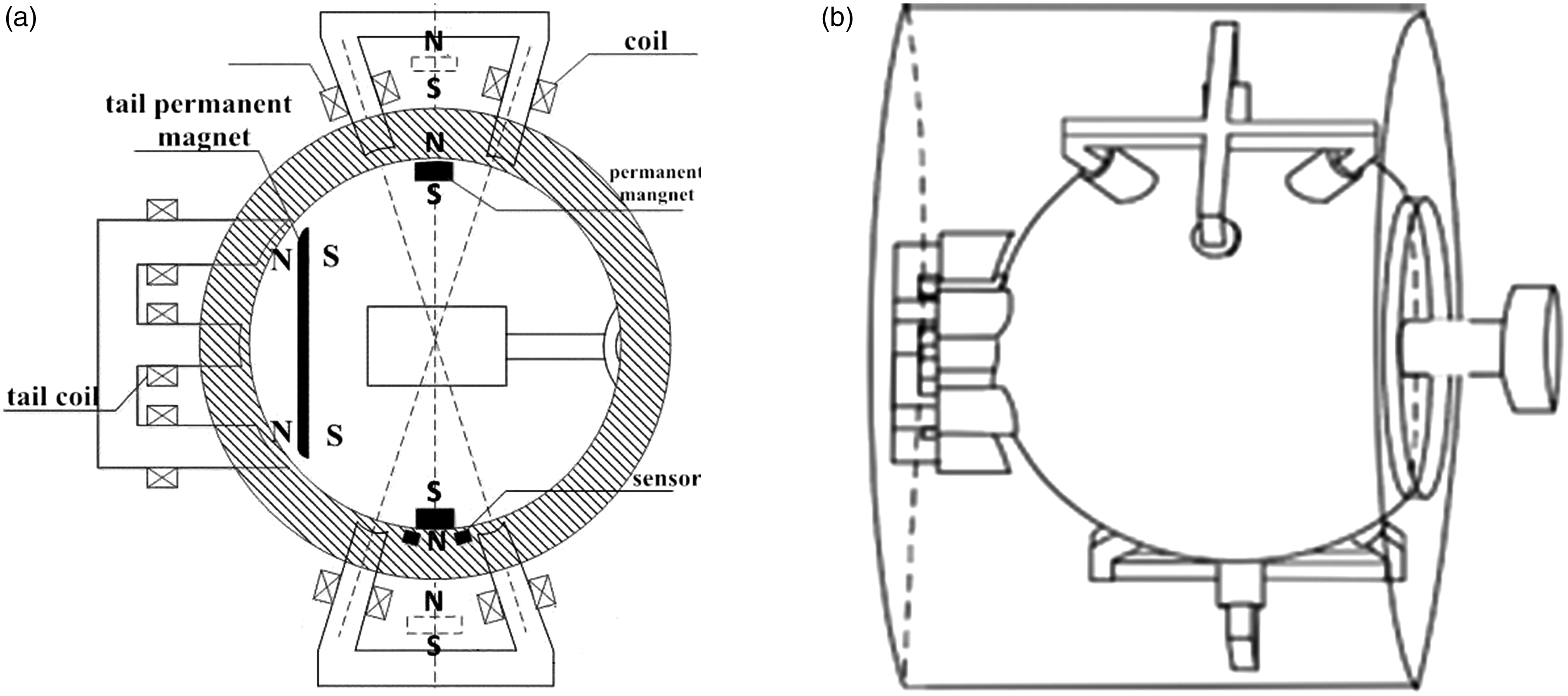
The structure diagram: (a) model with non-output shaft and (b) model with the output shaft.
A large range of adjustable permanent magnet is embedded in the vertical direction of the rotor shell, and a single stage fine-tuned permanent magnet is embedded in the tail. The rotation and deflection of the motor rotor is realized by the combination of two control modes that the control accuracy of the motor is effectively improved. Because gap is filled with liquid oil film between the stator and rotor, it has a certain lubrication effect, which reduces the friction resistance in the rotor rotation. The loss of motor is greatly reduced due to this structure, which is easier to control. According to the structure which is mentioned above, the assumption of a modeling process can be shown as follows: (1) ignore the magnetic circuit saturation; (2) during the research of magnetic field, ignore the eddy current effects caused by magnetic field changes; (3) the magnetic field created by the energized coils only has effects on the rotor magnetic poles which is nearby the coils. The magnetic field has less effects on rotor magnetic poles which is not adjacent to the coils so that the magnetic field can be ignored. (4) The magnetic material is isotropic medium and (5) the inertia force and gravity of liquid oil film can be neglected.
Model building
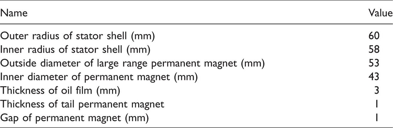
The FEM of multi-DOF PMSM is shown in Figure 2. The non-output shaft rotor structure is adopted by the motor, and the Nd-Fe-B materials are used for permanent magnets. The permanent magnet is fixed on the inner side of the rotor shell, by adjusting the current on the coil and changing the strategy of the electrified coil, the change of the magnetic field on the coil can be controlled, and the permanent magnet and the rotor can be rotated. The materials used for the stator and rotor are all steel structures, the detailed data are listed in Table 1.
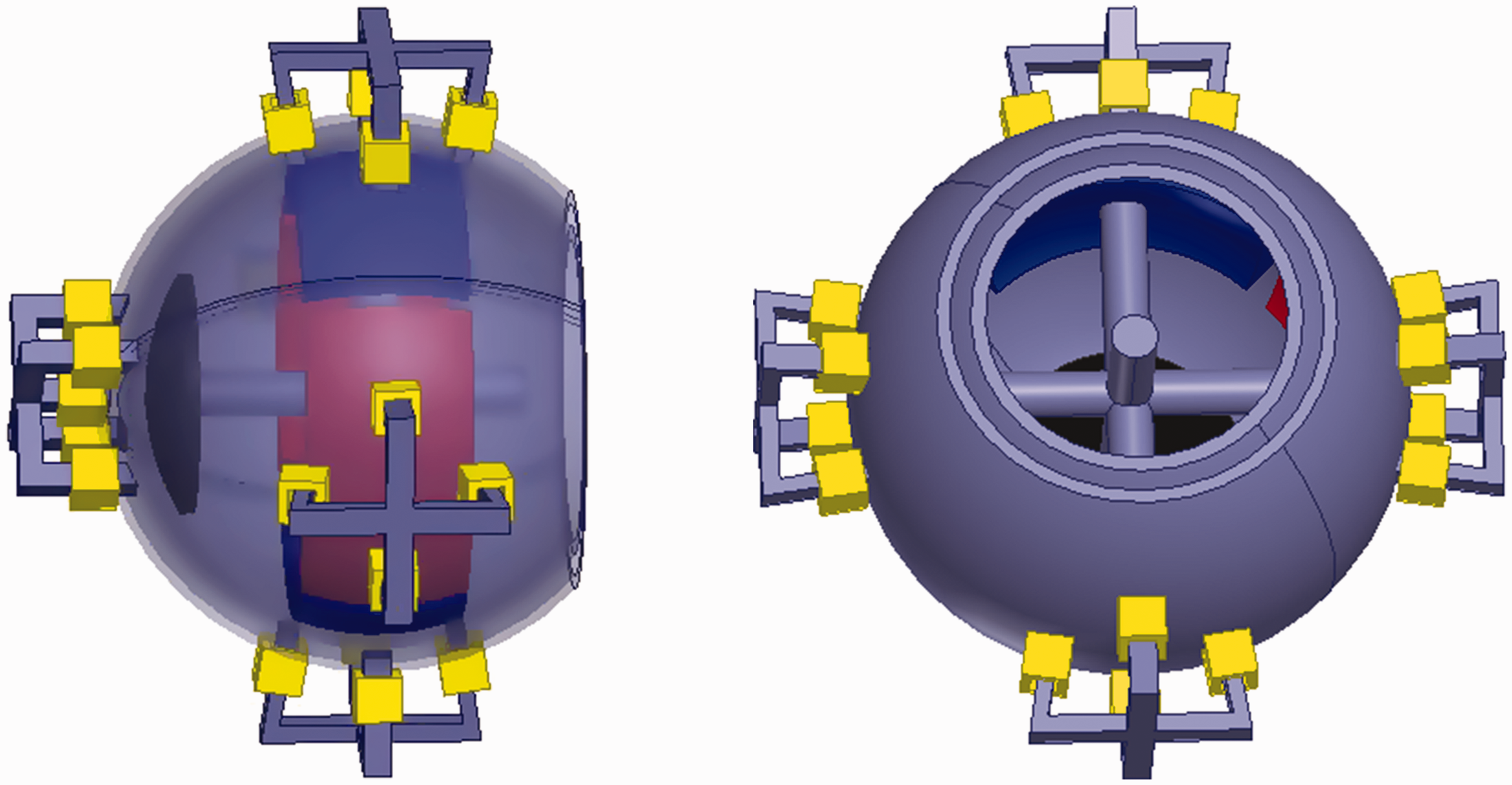
Motor model.
The detailed data.
Theory analysis
Principle of rotor modal
As the eccentricity will occur during the operation of the motor, there is always a difference between the barycenter of the rotor and the rotation center of the rotor. When the mass distribution of the spherical rotor is not uniform, the vibration and eccentricity are caused by rotor rotation, which are particularly obvious. It is one of the factors that affect the normal operation of the motor. According to the finite element theory of elastic mechanics, the equation of motion of the rotor system can be expressed in equation (1)

When the autorotation is only considered for the motor, and the eccentric does not occur on the rotor, the differential equation of rotor dynamics can be expressed in equation (2)
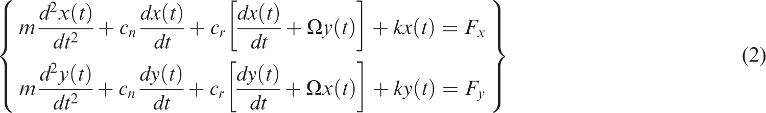
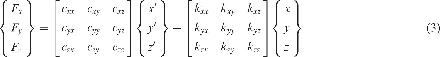
When the rotor is deflected and the force in the Z-axis direction is considered, the differential equation of rotor dynamics of motor can be expressed in equation (3)
In this model, the same stiffness coefficient of bearing can be expressed as K. The displacement of the rotor system of the motor can be expressed in equation (4)


Equation (6) shows the solution of S

From the roots of the equation, it can be seen that S has two roots. The two solutions of the S represent the amplitude and natural frequency of the rotor displacement under free rotation. The rotor is freely rotated with bearing support. Because the external condition of the rotor is idealized and the external damping is negligible, the natural frequency without damping can be expressed in equation (7)

Comparative analysis
When the motor rotor has a uniform density, the rotary axis is the central axis. The rotor with uniform density is removed from the motor, which is regarded as a free state.
17
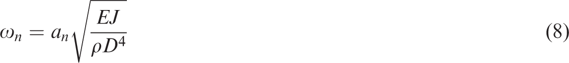
Without bearing support, the natural frequency of the rotor can be expressed in equation (8)
The two methods of FEM and analytical method are used to test the frequency of the rotor in free state. 22 The comparison result is shown in Table 2.
Comparison of the modal analysis results.
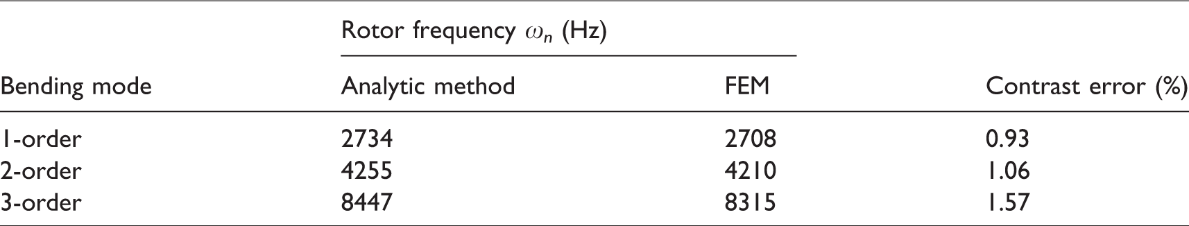
When analytical method is used to verify the dynamic problem of rotor under free state, the conditions are more complicated, so all are idealized models. The following assumptions are put forward: (1) the density of the rotor is uniform with no weld seam; (2) the rotation axis of the rotor is the central axis, and no eccentric will occur; (3) the external damping is ignored and the influence of air resistance is also not considered. As can be seen from Table 2, the contrast error result is within 3%, and the result of the analytical method is slightly larger than that of the FEM. It can be seen that the model established by analytic method is more idealized.
Modal analysis of rotor
Comparative analysis
Modal analyses are carried out on the rotor of the liquid suspension multi-DOF PMSM with the output shaft rotor as the model. In the free state, the first- and second-order modes of the rotor are shown in Figure 3, which belongs to bend deformation mode. In consideration of the bearing bracing, the first two order modal of the rotor analysis diagram with bearing rigidity is shown in Figure 4, and the first two order deformation is also bending deformation. In the free state, the natural frequencies of the rotor are all greater than the natural frequencies of the rotor with bearing support, under the same order modal.
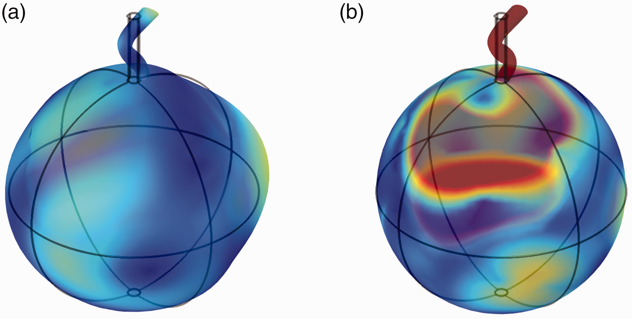
The rotor modals in free state: (a) the 1-order modal and (b) the 2-order modal.
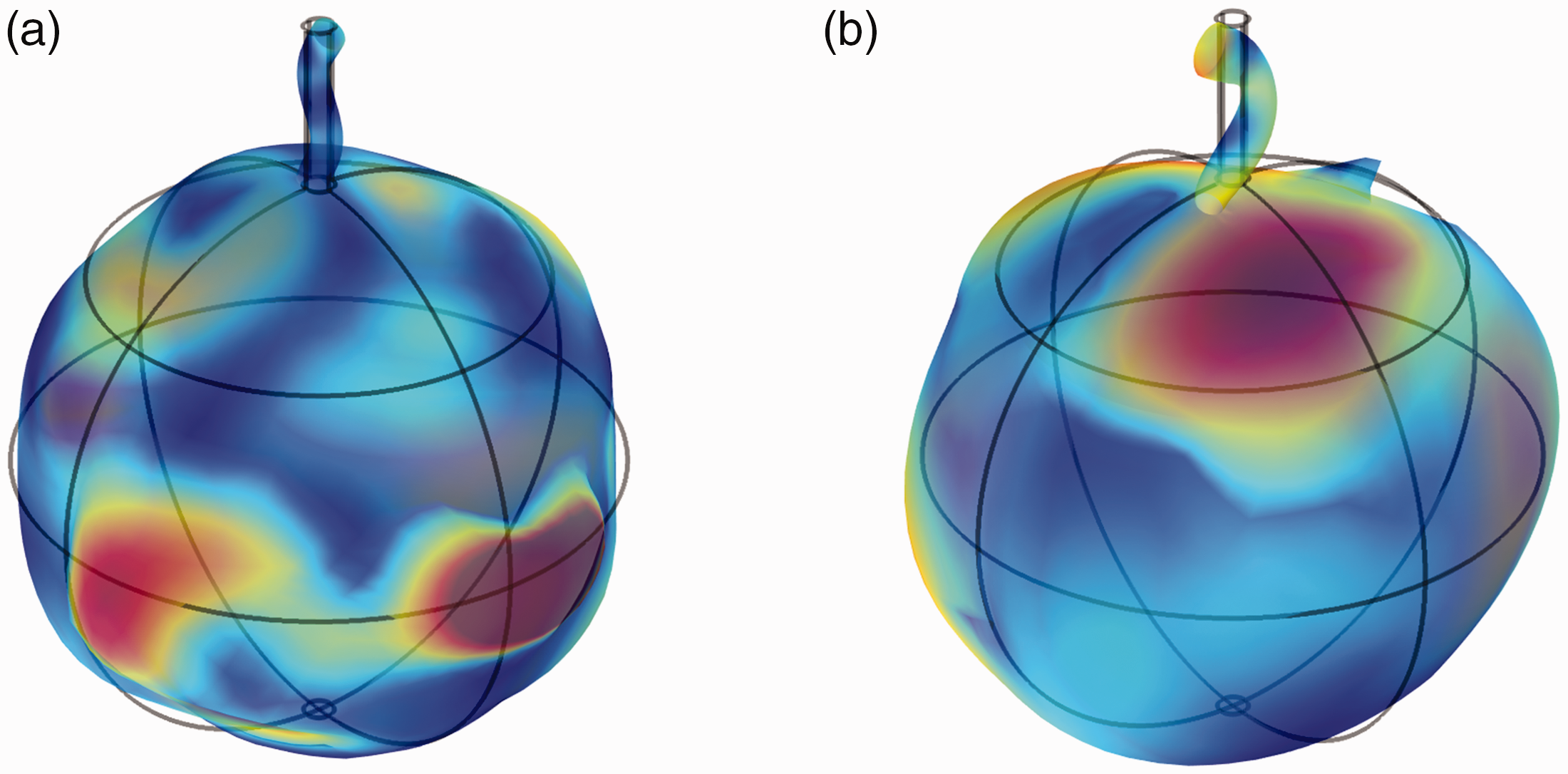
The rotor modal of magnetic bearings: (a) the 1-order modal and (b) the 2-order modal.
From Figures 3 and 4, in the free state, it can be seen that the force deformation of the first two order modes are mainly distributed near the connection between the spherical shell and the output shaft, which shows that deformation occurs easily and more stress is created near the rotor joint. In the state of bearing support, stress and deformation of the 1-order mode of rotor are mainly distributed in the vicinity of the rotor equator. Under the 1-order modal, most of stress and deformation of the rotor is caused by the centrifugal force on the equator of rotor. When the rotor speed is increased and exceeds the critical speed of 1-order modal, the position of the force deformation is also changing, which gradually moves to the junction of between the shaft and the spherical shell from the equator of the rotor. It shows that if the motor speed is too large, the material strength of the rotor connection is strengthened.
The effect of the gyroscopic effect on the critical speed
When the motor is in operation, the rotor speed will not be affected greatly, when the external loads change because the gyroscopic effect will maintain the rotating inertia of the rotor. However, the critical speed of the motor will be influenced by the gyroscopic effect of rotor. In the rotor dynamic simulation analysis, the gyroscopic effect of the rotor should be considered to prevent the inertial force from affecting the normal operation of the motor. The FEM can be used to test whether the rotor gyroscopic effect will affect the operation of the motor. As shown in Figure 5, the Campbell diagram of the modal frequencies varies with the different speed.
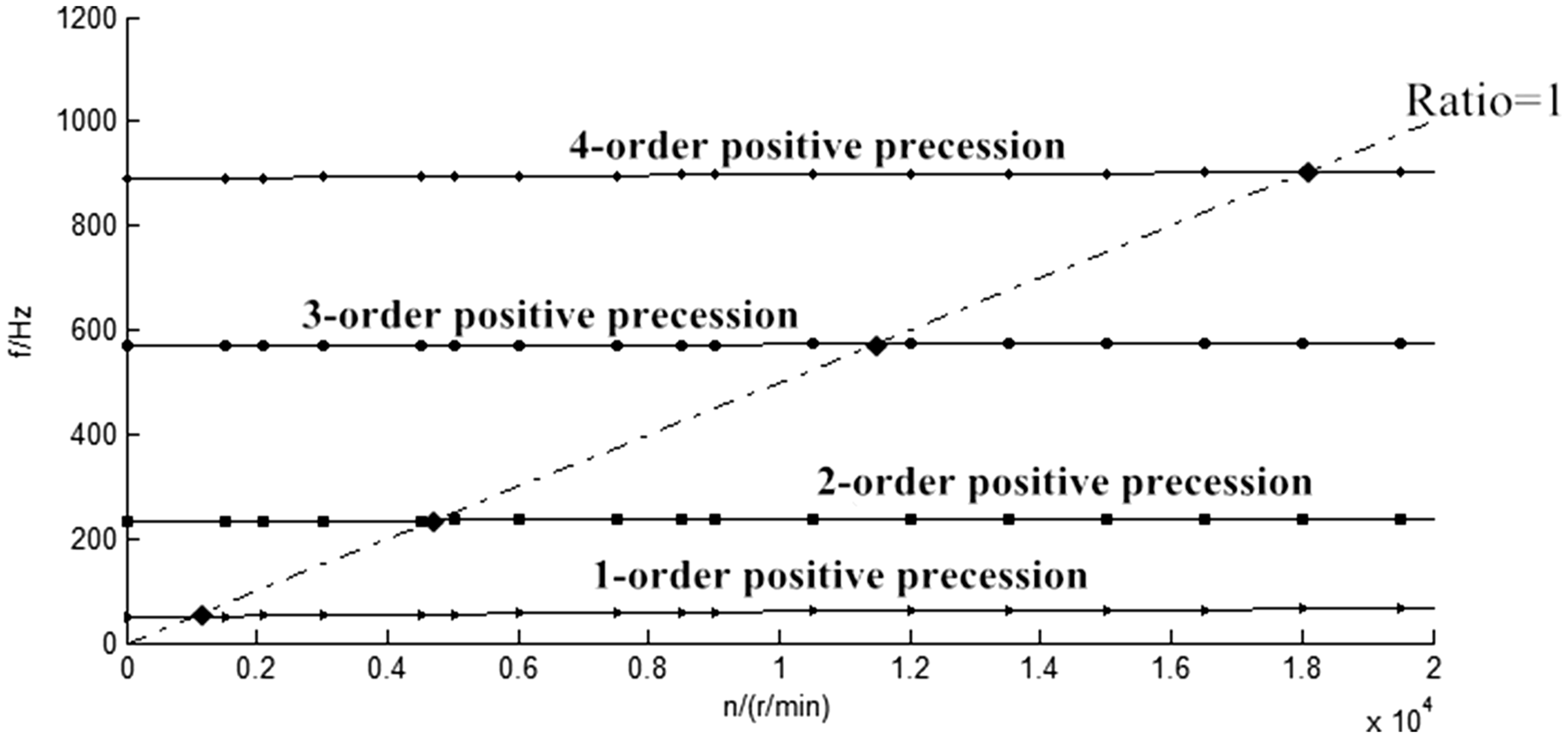
Campbell graft.
As shown in Figure 5, the dotted line of ratio = 1 is defined as a curve that the critical speed is equal to the motor speed. As shown in Figure 5, the rhombus intersection is the intersection point between the curve of ratio = 1 and the natural frequency curve of positive precession of every order mode. It is also called the critical speed of motor rotor at different rotational speeds, under gyroscopes effect. After the gyroscopic effect is taken into consideration, the rotor modes of motor are divided into two parts: forward precession and backward precession. Figure 5 is the forward precession of the rotor modal. The forward precession frequency of rotor will increase with the increasing speed, but the amplitude of rise will be smaller, which is within 5 Hz. It is shown that the speed is increasing, but the first four-order mode frequencies of the rotor will not change in large range. It is indicated that the influence of gyroscopic effect on critical speed can be neglected during designing and optimizing of the motor.
Influence of rotor rigidity on critical speed
The critical speed of the rotor will be influenced by many factors, such as rotor material stiffness, rotor size, and so on. Therefore, many factors should be considered when optimizing the design of motor. As shown in Figure 6, the influence of rotor material of different stiffness on critical speed of motor rotor is discussed.
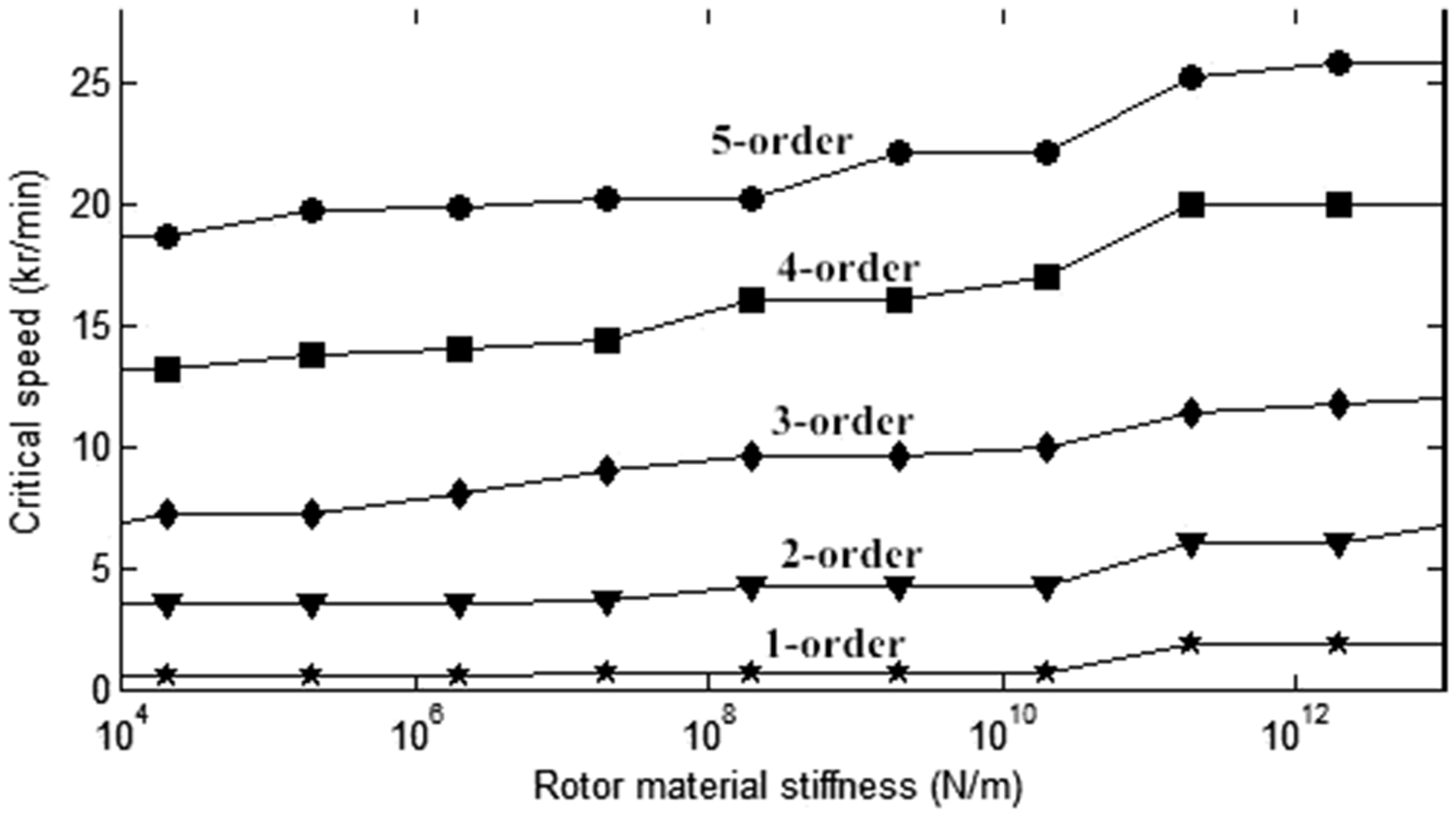
The influence of the rigidity of the rotor material on the critical speed.
It can be seen from Figure 6 that the change of critical speed with material stiffness is small when the rotor runs in 1-order and 2-order modes, but the variation range of critical speed of the 3–5-order rotor is greatly affected. When the stiffness of rotor material is less than 106 N/m, the 1–5-order mode critical speed basically does not changed. When the material stiffness is greater than 108 N/m, the critical speeds of every order mode are increasing. When the stiffness is greater than 1010 N/m, the critical speed of each order mode increases significantly. When the rotor stiffness is greater than 1012 N/m, the critical speeds of all modes basically tend to be stable and with only small variations. Not only the critical speed of each order mode will change with the stiffness of the rotor material but also the bending mode of the rotor will be affected by the stiffness of the material. Because the spherical rotor is used in the multi-DOF PMSM, it will be subjected to different directions in the operation, so that the rotor will undergo bending deformation. Therefore, based on the rotor dynamic problems of motor, the deformation and displacement of rotor’s bending modes under different stiffness should be considered, as shown in Figure 7.
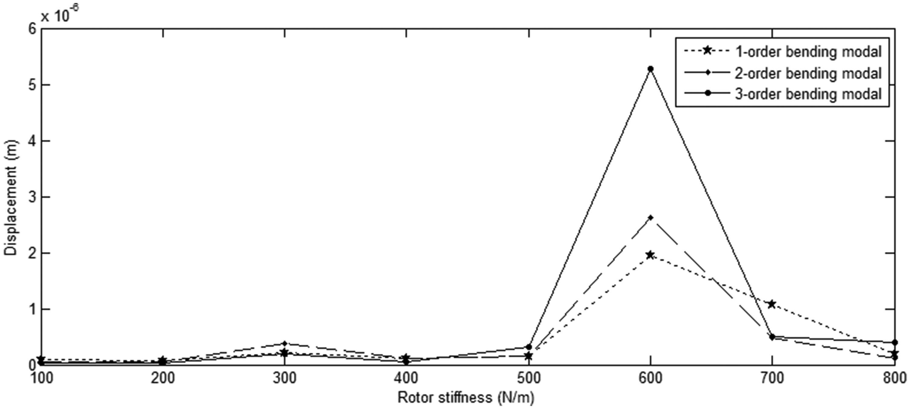
The influence of the rigidity of the rotor material on the amplitude of the bending modal.
Figure 7 shows the influence of rotor stiffness on bending modal displacement. In the first-order bending mode, it can be seen from the diagram that the influence of rotor deformation is mainly that the stiffness is greater than 108 N/m. Before the bearing stiffness is less than 108 N/m, the displacement and deformations of the 2- and 3-order bending mode have little influence. When the rotor stiffness is between 108 N/m and 1010 N/m, the displacement of the first three order bending modes will first increase and then decrease. The deformation displacement will reach the peak at the rotor stiffness of 109 N/m. Although the deformation and displacement values are very small, resonance problems may be produced at this point, which will affect the normal operation of the motor.
Analysis of experimental results
Vibration analysis experiments were carried out on the stator shells filled with different liquids. The experimental platform is shown in Figure 8. The rotor with output shaft is experimentally studied using vibration displacement sensor TIME7231, motor driver, and rotor spherical shell. The rotor is rotated at different speeds, and the weak deformation on the stator shell under different liquid conditions is tested.
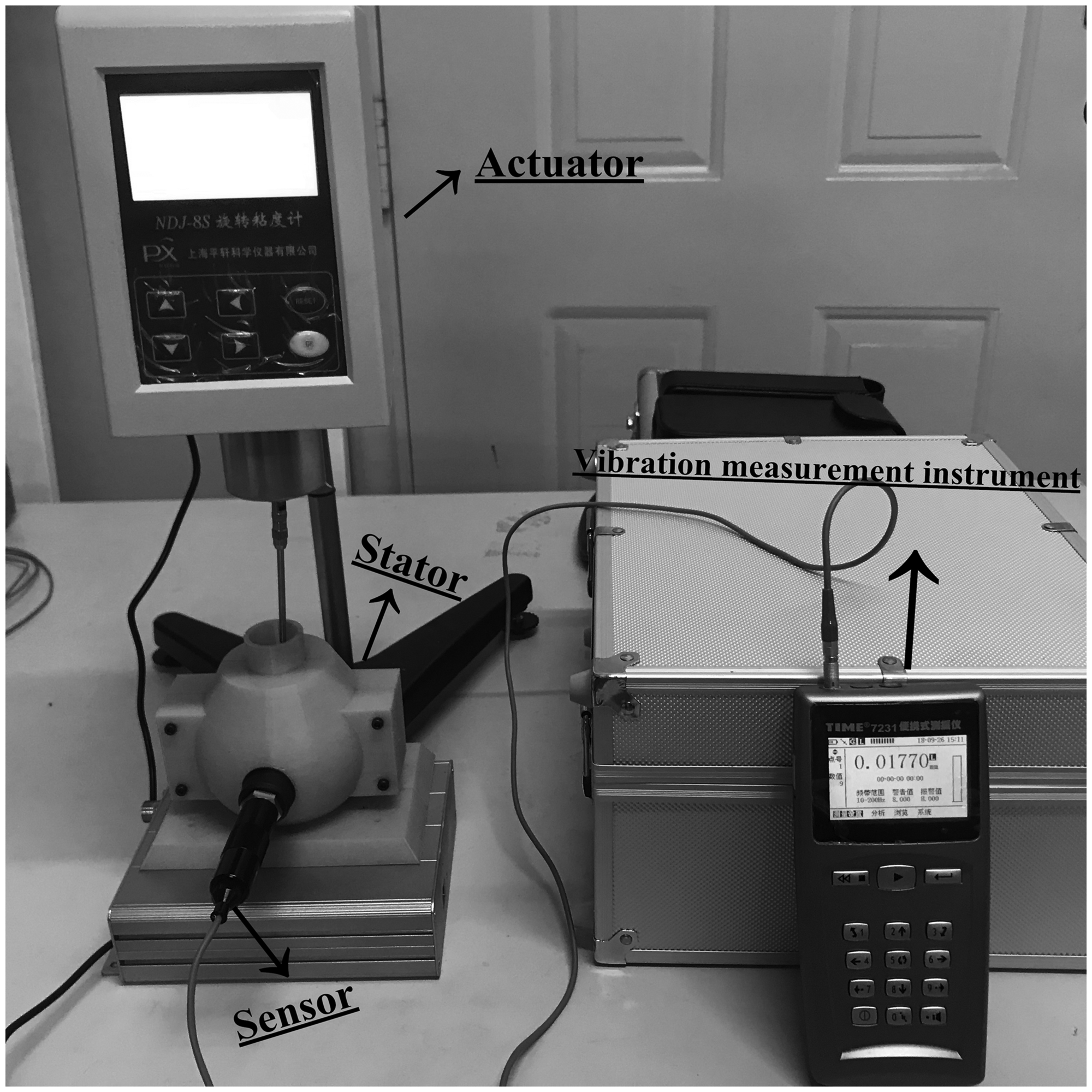
The experimental platform.
As can be seen in Figure 9, the rotor speed increases gradually under different liquid conditions, and the deformation displacement of the stator shell caused by the flow of the liquid also increases gradually. Within the speed of 20 rad/s, water and oil are filled into the stator shell, and the difference of deformation displacement is not obvious. When the rotational speed is greater than 20 rad/s, the deformation displacement of the stator filled with oil film is obviously smaller than that filled with water. This indicates that the oil film can play a role of lubrication and shock absorption between the stator and the rotor.
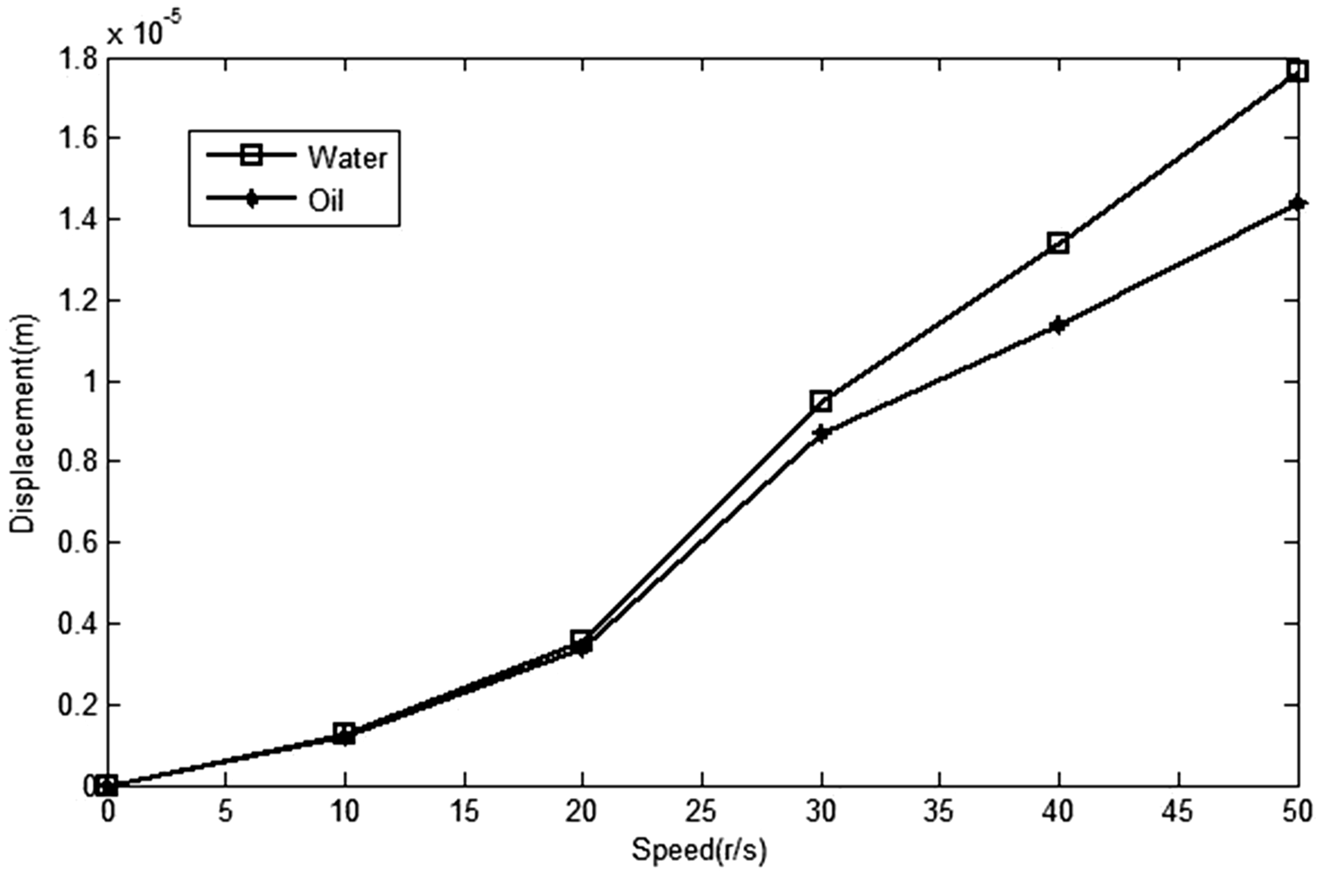
Deformation in different liquids.
The relationship between the rotational speed and the vibration amplitude of a rotor spherical shell with a stiffness of 1012 N/m is tested. According to Figure 4(a), the force of the rotor in the 1-order modal is concentrated near the equator of spherical shell. So the sensor is attached to the outer equator of the spherical shell, and the vibration amplitude of the rotor is collected and processed. Then the motor driver is used to change the speed of the motor, and the vibration amplitude at the equator of the spherical rotor is observed and recorded at different speeds.
Through the experimental platform, the relationship between the rotor speed and the deformation displacement is obtained from the output data of the sensor, as shown in Figure 10.
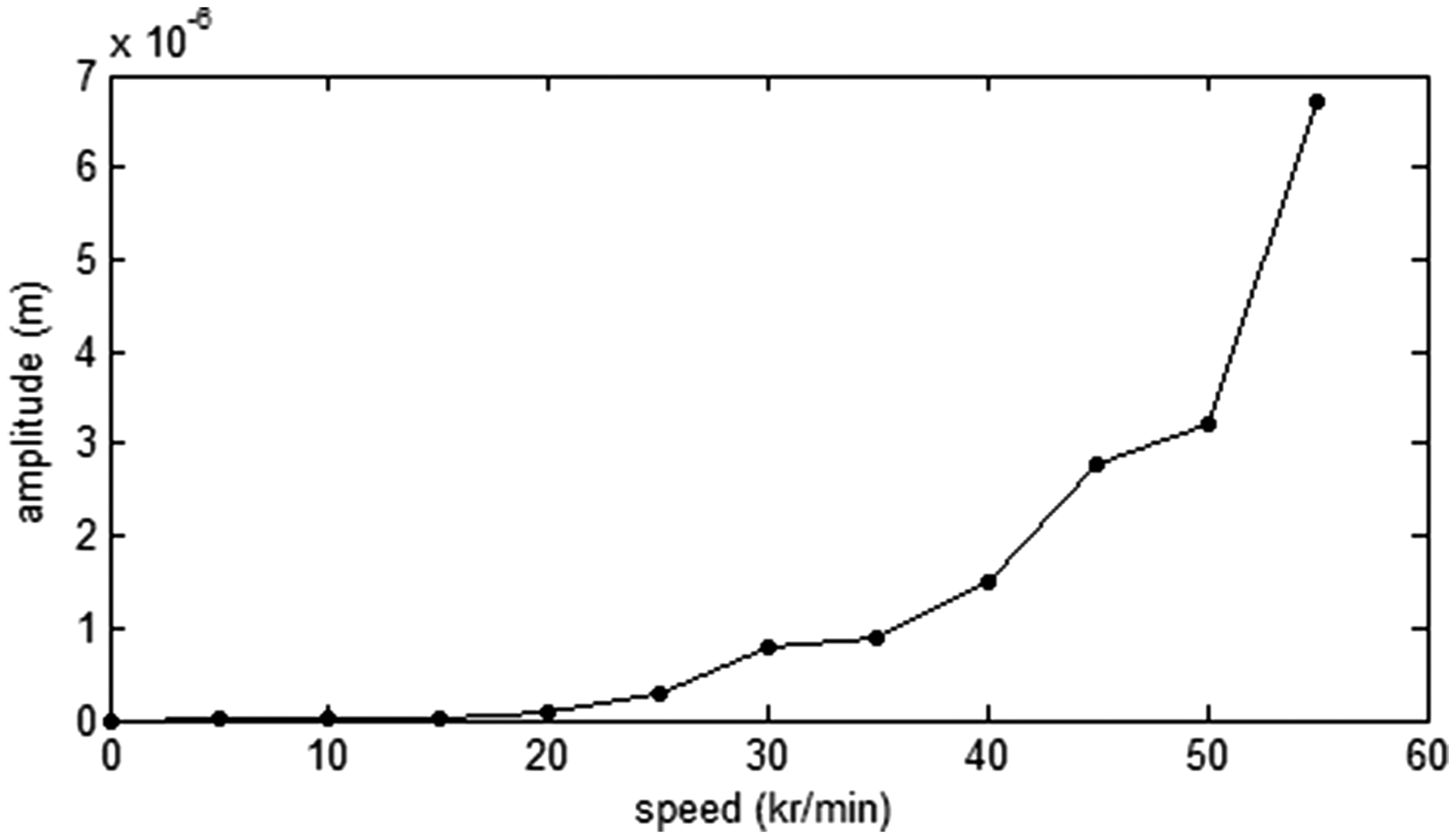
Vibration experimental results.
Under the free state, it can be seen from Figure 10 that the vibration amplitude of the rotor is very small, when the rotor speed is less than 1.2 kr/min. When the rotor speed is increased from 0 kr/min to 1.2 kr/minn, the change of amplitude is also very small. It is indicated that the rotor is relatively stable in this section. When the speed is greater than 1.2 kr/min, the vibration amplitude of rotor is also increased. When the speed is up to 3 kr/min, the vibration and displacement of the rotor reach the maximum value, and the speed reaches the critical speed of 1-order mode. In the free state, the first-order modal critical speed of rotor measured by FEM is basically consistent with the data obtained by experimental method.
Conclusion
The rotor dynamics of a liquid solid suspension multi-DOF PMSM is analyzed. Based on the FEM and analytical method, combined with the rotor dynamic analysis method, the following conclusions can be drawn:
The accuracy of the FEM is verified by comparing and analyzing the data of FEM and the analytical method. It is concluded that the finite element results are closer to the actual situation and the error range is calculated. When the motor is rotating, the gyroscopic effect of the rotor is considered, and the Campbell diagram of the rotor is calculated. The gyroscopic effect of motor rotor has little effect on critical speed, so the effect of gyroscopic effect on the critical speed in design can be ignored. The relationship between the critical speed and the stiffnesss of the rotor bearing is studied. It is shown that the critical speed will increase in the process of the rotor stiffness change from 103 N/m to 1013 N/m. When the stiffness reaches 1012 N/m, the increasing trend of the critical speed decreases and tends to be stable. Based on the 3-DOF rotor experimental platform, the vibration amplitude of the rotor at different speeds is measured. The critical speed of the 1-order is about 3 Kr/min, which is consistent with the conclusion of the FEM.
The results of calculation and analysis provide theoretical basis and data for optimal design and control of motor.
Footnotes
Declaration of conflicting interests
The author(s) declared no potential conflicts of interest with respect to the research, authorship, and/or publication of this article.
Funding
The author(s) disclosed receipt of the following financial support for the research, authorship, and/or publication of this article: This research was funded by the National Natural Science Foundation of China (Nos. 51577048, 51877070, 51637001), the Natural Science Foundation of Hebei Province of China (No. E2018208155), the Overseas Students Science and Technology Activities Funding Project of Hebei Province (No. C2015003044), the Hebei Industrial Technology Research Institute of Additive Manufacturing (Hebei University of Science and Technology) open projects funding, the National Engineering Laboratory of Energy-saving Motor & Control Technique, Anhui University (No. KFKT201804), key project of science and technology research in Hebei provincial colleges and universities (ZD2018228).