
Abstract
When running in idle condition, the vehicle has no speeds and road excitation, and the engine vertical self-vibration is the main excitation source. In this paper, a five-degree-of-freedom half-vehicle suspension model with double-delay feedback control is proposed to improve the vibration performance in idle condition. First, according to the system amplitude–frequency characteristic, the multiobjective function combining the vehicle body acceleration and pitching angular acceleration is established. Then, utilizing particle swarm optimization in optimizing and analyzing, the optimal feedback gains and time delays of the suspension system are obtained. Subsequently, a new frequency scanning method is utilized to analyze the stability of the controlled suspension system with the optimal feedback parameters. Finally, numerical simulations in the Matlab/Simulink environment are conducted to validate the performance of time-delay reducing vibration control on different engine feedback condition. Simulation results indicate that the active suspension with time-delay feedback control based on engine acceleration has better reducing vibration performance, and the root mean square of vehicle body and pitching angular acceleration are, respectively, reduced 87.37 and 80.01% than that without time delay. The research on vehicle suspension system with time-delay feedback control can improve the vibration performance effectively compared to the conventional one.
Introduction
Many scholars have done a lot of theoretical and experimental research in vehicle semi-active suspension and active suspension1–3 since the active control theory was proposed. With the continuous improvement of the suspension system, the accuracy of control system has been improving rapidly. However, in actual engineering, the realization of active control strategy depends on the sensors and processors. In order to achieve better suspension performance, it is necessary to demand more efficient signal processing and the time delay between signal collection and action execution should be considered. Therefore, it is of great theoretical and practical value to design the active suspension control system with time delay to ensure the stability of the control system and improve the vibration performance of the suspension.
Olgac and co-workers4–7 presented the new concept of active vibration absorption for dynamic structures, which found the vibration behavior can be controlled with time delay and the mechanism was utilization of a controlled time delay into the feedback loop. When the proper selection of time delay and feedback gain converted the absorber into a resonator at a desired absorption frequency, the dynamic response of the main system would be completely absorbed. To demonstrate the validity of the multiple dynamic responses, Jalili and Olgac 8 studied a combination of two identical dynamic responses on a 3-DOF structure and gave the critical stability region under the time-delay controlling. Xu J and Sun Y 9 by applying experiment verified the effect of system vibration with time delay or not. Zhao and Xu10,11 studied the effect of time delay on linear and nonlinear dynamic absorbers and adjusted the vibration effect by optimizing feedback gain and time delay. Tootoonchi and Gholami 12 and Tomáš et al. 13 applied the system’s time-delay acceleration feedback to reduce the main system vibration response. However, in the study of ride comfort, the additional dynamic absorber is often limited by the layout of the vehicle structure. In recent years, with the improved requirements of ride comfort, the automobile manufacturing industry has paid more and more attention to the vibration characteristics in idle condition. Besides, most scholars studied the engine vibration response by changing the natural frequency characteristics of the suspension system,14,15 which only stayed in the level of optimizing the stiffness and damping of the engine suspension. Therefore, optimizing the engine suspension system and reducing the vibration performance have become an important development trend currently.
In idle condition, engine self-vibration is the major excitation source. For four-stroke engines, Crankshaft’s speed in working stroke is obviously higher than the rest and the periodic variation causes itself rigid vibration and flexible vibration of the power assembly mounting system, which is the main reason for the engine vibration.14,16,17 Besides, the abnormal combustion of gasoline, parts impact, flywheel, and other eccentric rotation 18 also lead to engine vibration in a certain frequency. The engine vibration transmitting through suspension system causes a series of first and second resonance, 14 which result in vehicle body structural fatigue and noise problems. Furthermore, the development tendency of vehicle technology puts forward higher requirements for the power assembly suspension system, which is mainly reflected on lightweight of automobile body. So it is very important to design reasonable engine suspension system.
Although the engine suspension system is complex multidegrees of freedom dynamic model, the vehicle does not have the running speed and vibration excitation from road surface in idle condition. Therefore, the main vibration comes from the self-engine vertical excitation. When the engine is symmetrically distributed along the central axis of the vehicle, the vibration response is symmetrical, and so the five-degree-of-freedom half-vehicle model 19 can effectively reflect the whole vibration characteristics in idle condition. In this paper, the double-delay feedback control is introduced to the suspension model based on the theory of time-delay dynamic absorber. Select reasonable weight coefficients and utilize the multiobjective function on the vehicle body acceleration (BA) and pitching angular acceleration to obtain optimization parameters and analyze the system stability. Finally, numerical simulation in the time domain and frequency domain, respectively, under the Matlab/Simulink environment validates the effect of vehicle vibration.
Mechanical model
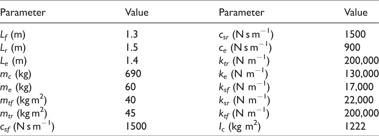
Vehicle suspension is a complex multi-degree-of-freedom vibration system, which has any amount of time-varying, nonlinear and uncertain factors. In order to facilitate the analysis of time-delay suspension system in idle condition, the vehicle is simplified as a linear dynamic model. Figure 1 is a simplified five-degree-of-freedom model, 19 which mainly considers vertical and pitch movement of the body mass, the vertical movement of front and rear wheels, and the vertical movement in self-engine. The parameters 19 of the model are shown in Table 1, where Lf and Lr are the distance from the center of mass of the vehicle body to the front and rear axles, respectively; Le represents the distance from the center of mass of the vehicle body to the center of the engine; mc and Ic represent body mass and moment of inertia, respectively; mtf, mtr, and me represent the front wheel mass, rear wheel mass, and engine mass, respectively; in Figure 1, xc, xtf, xtr, xe, and ϕ, respectively, represent the vehicle body displacement, front wheel displacement, rear wheel displacement, engine displacement, and vehicle body pitching angle; ksf, csf, ksr, and csr are the stiffness and damping coefficient of the front and rear suspension system, respectively; ke and ce, respectively, represent the stiffness and damping coefficient of the engine suspension; ktf and ktr, respectively, represent front and rear tire stiffness.
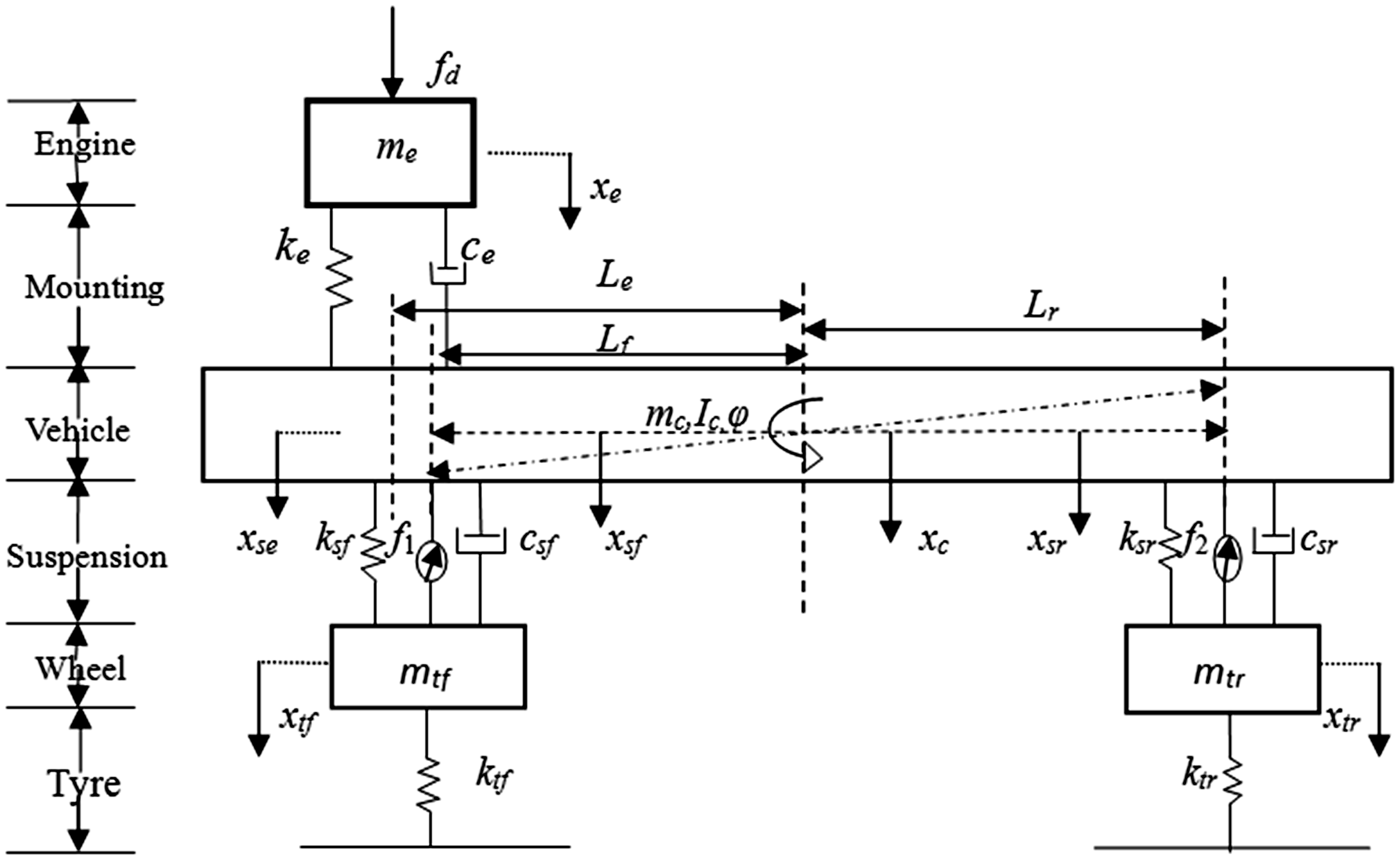
Five-degree-of-freedom half-car model in idle condition.
Model parameters of vehicle suspension.
It should be noted that choosing the right number of cylinders and crank arrangement can effectively reduce or eliminate the interference force and torque. According to the characteristics of the four-stroke four-cylinder gasoline engine of the passenger car in Ye,
14
Yuan et al.,
15
and Zhang
16
it can be shown that when the crank angle choose 180° and firing order is as 1–3–4–2, there is only the second-order reciprocating harmonic inertia force in the vertical direction. The exciting force can be written as

Here, m is the mass of single-cylinder piston and part of reciprocating motion; r is the crank radius; λ = r/l, that is the ratio of the crank radius to the length of the connecting rod; ω = n/60, that is the crankshaft rotation speed; n is the engine speed.
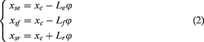
As the body pitching angle is small, it can be approximated as
According to the Newton’s second law, the differential equation can be established.
The vertical motion equation of vehicle engine is shown as

The vertical motion equation of vehicle body is shown as

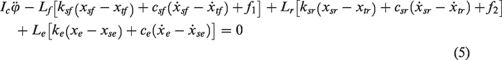
The body pitching motion equation is shown as
The vertical motion equation of the front wheel (nonsprung mass) is shown as

The vertical motion equation of the rear wheel (nonsprung mass) is shown as

The time-delay feedback control force is defined as

The optimization of controlling parameters
The multiobjective function is used to measure the vibration effect. The basic method is the original multivariate objective function that is constructed as a new evaluation function by linear weighting.20–23
If the excitation force has the Laplace transform form of 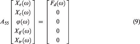
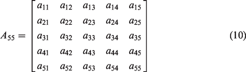
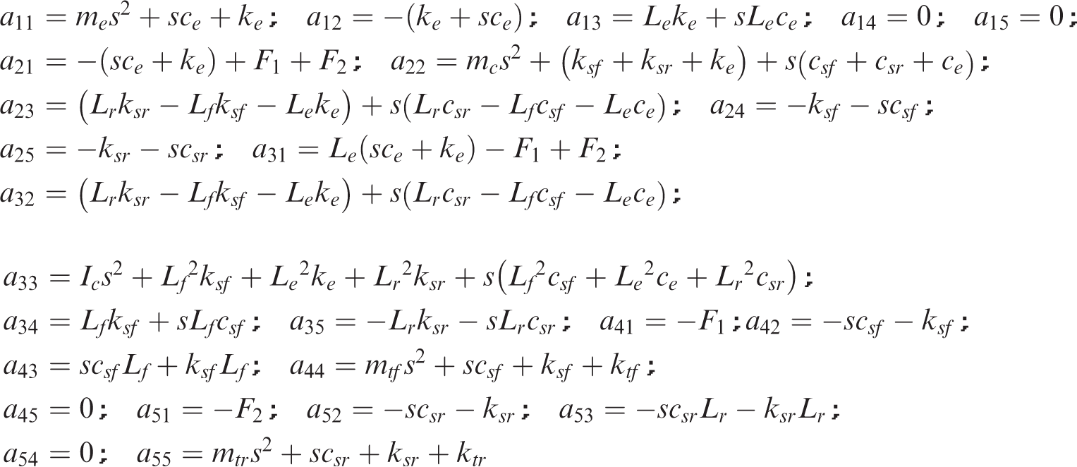
Here, A55 is a 5 × 5 matrix with time-delay feedback parameters, as follows
When the engine vibration displacement is used as feedback control variable, When the engine vibration velocity is used as feedback control variable, the feedback control force of the front and rear suspension can be written as
When the engine vibration acceleration is used as feedback control variable, the feedback control force can be written as


For the half car model, the vehicle BA and pitching angular acceleration are the most important characteristics to measure the vibration effect of vehicle suspension system. Taking the frequency response functions of the car BA and pitching acceleration (PA) as performance characteristics, the new multiobjective function J(g1, g2;τ1,τ2) is established, as shown in equation (11)
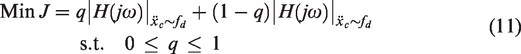
In which, considering the normal circumstance of driving, the values of weight coefficients are taken as q = 0.7 in this paper.
According to the evolutionary behavior of particle swarm optimization (PSO)24,25 in every iteration process (the code is shown as Appendix 1), the feedback variables are optimized and updated to get the optimal global control parameters of the front and rear suspensions in
When the engine vibration displacement is used as feedback control variable, after optimization, the control parameters are obtained as
When the engine vibration velocity is used as feedback control variable, after optimization, the control parameters are obtained as
When the engine vibration acceleration is used as feedback control variable, after optimization, the control parameters are obtained as


It can be concluded that the feedback gains have great difference based on different control strategies, and the feedback gain coefficients are the largest based on the engine displacement feedback and the feedback gains are the smallest on the engine acceleration feedback.
Stability analysis of time-delay system
It is well known that when time-delay feedback control is introduced, the unreasonable choice of feedback gains and time delays would destabilize the system. Therefore, it is necessary to analyze the stability of vehicle time-delay active control system.26,27
The characteristic equation of the system is obtained by equation (10) in

When the time delay τ > 0, the form of equation (12) can be written as

Furthermore, for the 
According to the theory of frequency domain scanning, if existing
Substituting
Therefore, the time delay is

For a purely imaginary root, i.e.
According to the above basic theory, substitute the feedback gain parameters into equation (12) and get the cross frequency, as shown in the following figures.
When the engine vibration displacement is used as feedback control variable, substitute the feedback parameters, i.e. g1, g2, and τ1, into equation (12) and implement frequency domain scanning in the interval
Figure 2(a) demonstrates that the system does not have cross frequencies, and the time-delay system is always stable. According to Figure 2(b), it is indicated that the system has one cross frequency, i.e. ω = 12.67, which indicates that the root is always crossing the virtual axis into the right half plane and the numbers of unstable root are increasing. Then the
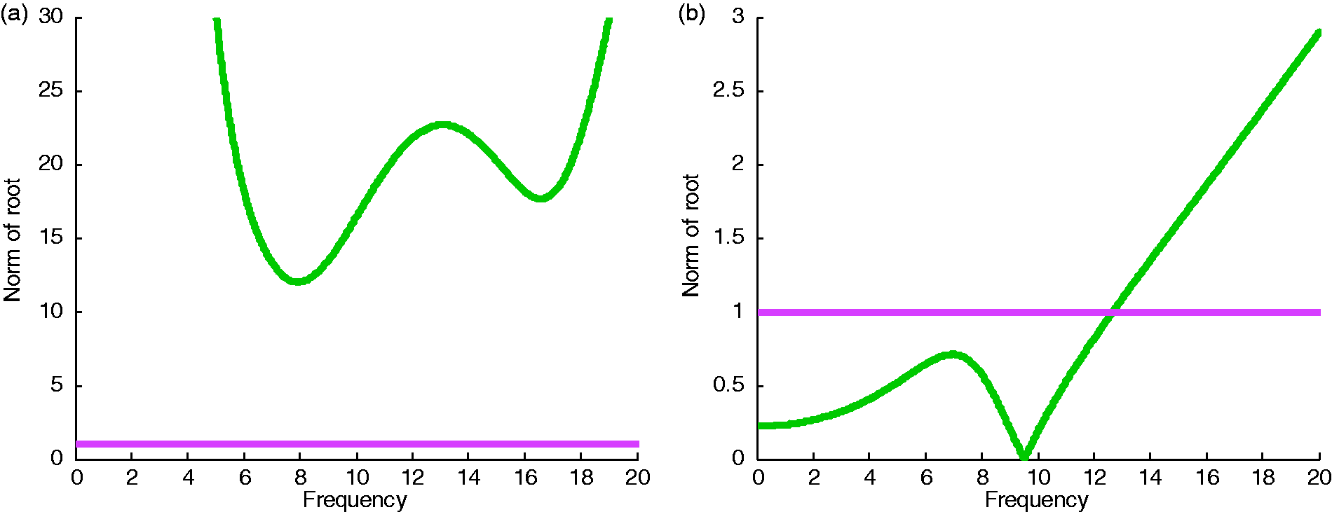
Norm of Z on displacement feedback. (a) τ2 unknown scanning image and (b) τ1 unknown scanning image.
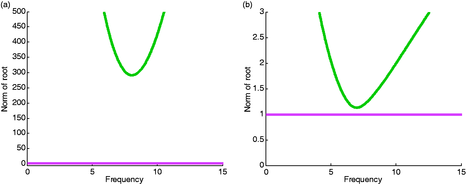
Norm of Z on velocity feedback. (a) τ2 unknown scanning image and (b) τ1 unknown scanning image.
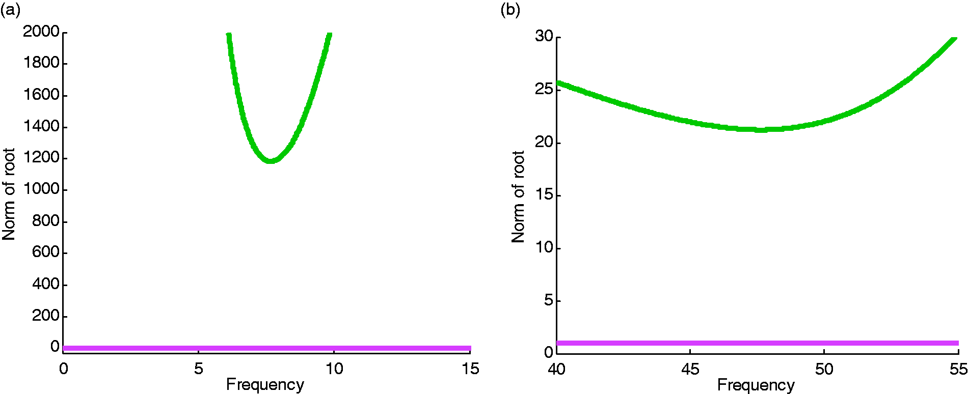
Norm of Z on acceleration feedback. (a) τ2 unknown scanning image and (b) τ1 unknown scanning image.
In summary, from the above analysis, the whole system is unstable.
2. When the engine vibration velocity is used as feedback control variable, the corresponding optimal values g1=1268 N m−1, g2 = −14 N m−1, and τ1=0.087 s, and then the scan theory is applied to get Figure 3(a). Similarly, substitute the feedback values, i.e. g1, g2, and τ2 and get Figure 3(b). The figures demonstrate that the system does not have cross frequencies, and the time-delay system is always stable. 3. When the engine vibration acceleration is used as feedback control variable, Figure 4 is obtained based on the above stable theory. The figures have no intersection, so the time-delay system is always stable.
Analysis of system vibration characteristics
In “Stability analysis of time-delay system” section, the stability of controlled system with the optimal time-delay control parameters is elaborated for different feedback control strategies. In this section, we will validate the superiority of the time-delay feedback control in the frequency and time domains.
Frequency domain characteristic
Taking the feedback gains g1 and g2 and time-delay value τ1 and τ2 into the system equation (11), the amplitude–frequency characteristic curve of the multifunction response can be obtained on different engine idling condition, as shown in Figure 5.
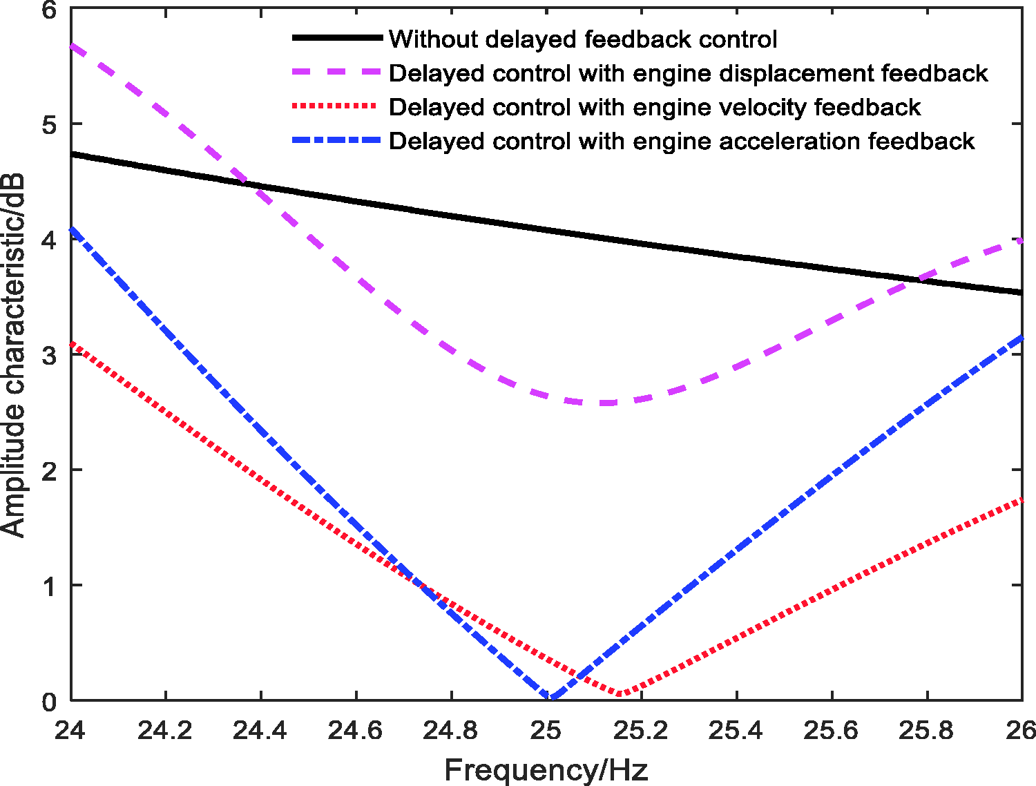
Feedback frequency domain.
It can be seen from Figure 5 that the time-delay feedback has a great influence on the objective function. Compared with the no time-delay control, the amplitude of the objective function has a different degree of increase and decrease in the frequency range. The curve changes smoothly based on the engine displacement, and the curve changes sharply based on the engine velocity or acceleration. In the frequency of 25 Hz, the curve based on the engine acceleration has the lowest point, which indicates the better performance after optimization.
Numerical simulation in frequency domain indicates that the time-delay feedback system can optimize the smooth performance of the vehicle compared with the passive system. There are different vibration effects on different feedback state and it is necessary to reasonably choose the feedback condition of the engine to match the time-delay system.
Time domain characteristic
Compared with the passive feedback control, the vibration responses with time-delay feedback in the time domain are shown in Figures 6 to 8.
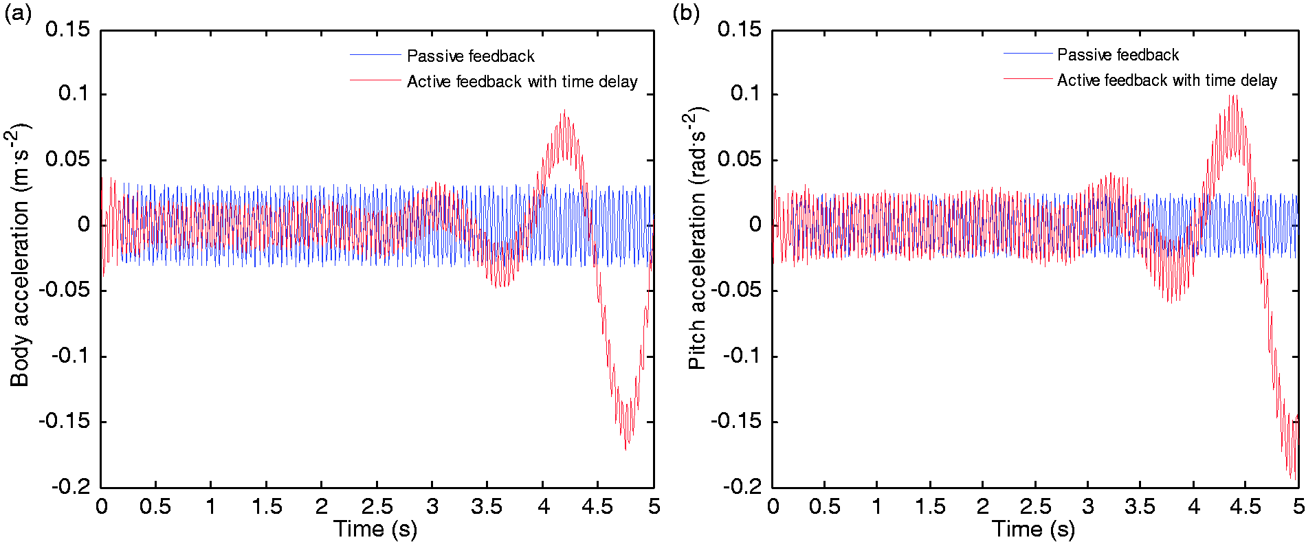
Response on engine displacement feedback. (a) Vehicle BA response and (b) vehicle pitching angular acceleration response.
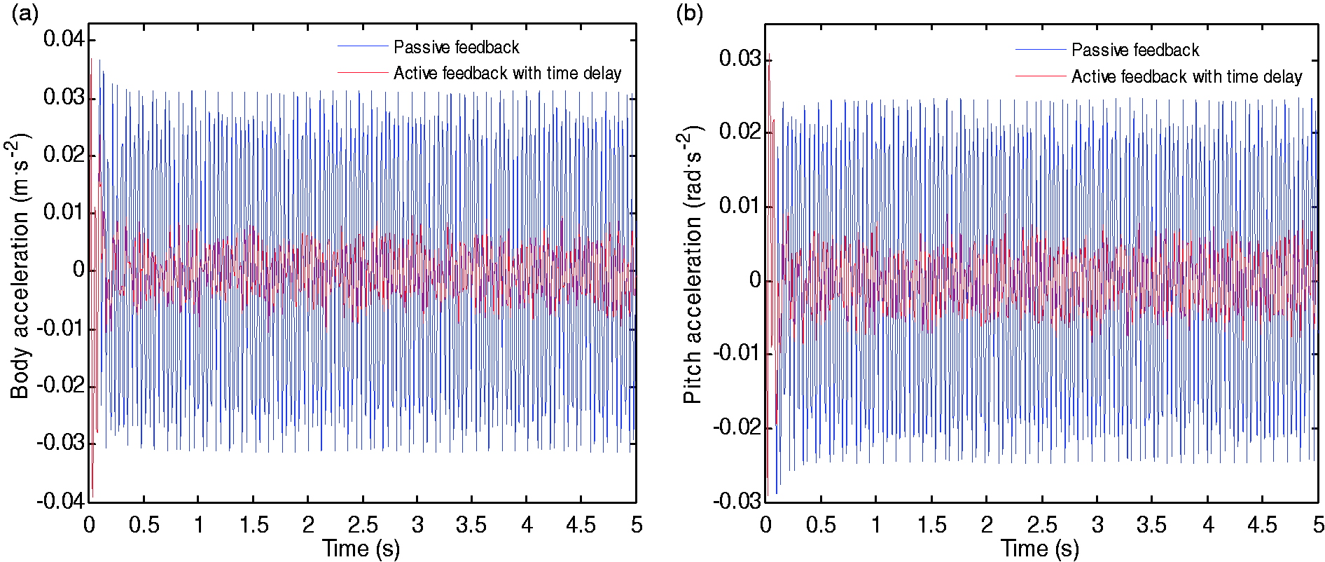
Response on engine velocity feedback. (a) Vehicle BA response and (b) vehicle pitching angular acceleration response.
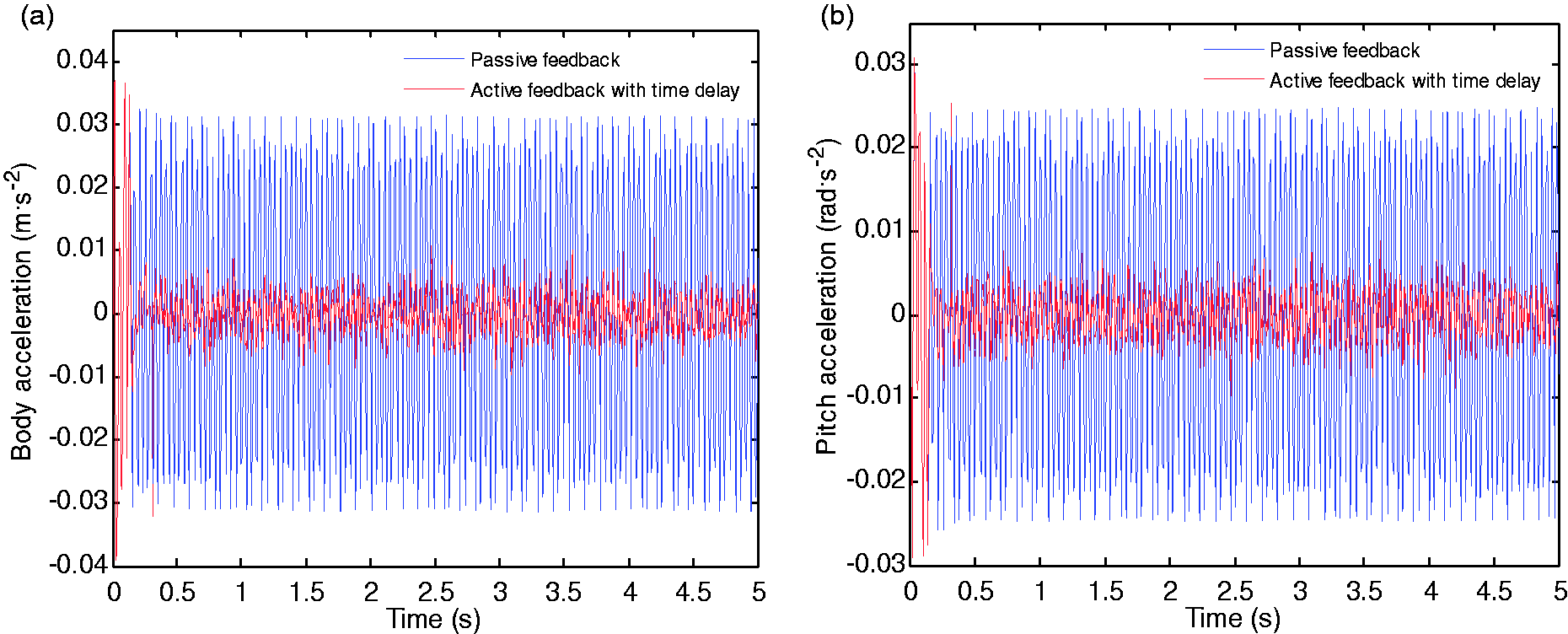
Response on engine acceleration feedback. (a) Vehicle BA response and (b) vehicle pitching angular acceleration response.
As displayed in Figures 6 to 8, when the responses of vibration tend to be stable gradually, the corresponding smooth performances of vehicle suspension system with time-delay feedback control are reduced dramatically. Compared with the passive feedback control, the active suspension with delay control makes the response of the vehicle BA and PA reduced significantly. When based on the engine displacement feedback, the response of the vehicle BA and PA is effective in a short time due to the system self’s response delay, but with the continuous response of the system, the whole system is losing stability and cannot achieve normal control. In Figure 2, we have obtained the reason of system instability based on displacement feedback through stability analysis. When based on the engine velocity feedback, the root mean square (RMS) of the accelerations is reduced from 0.0198 m s−2 and 0.0156 rad s−2 to 0.0028 m s−2 and 0.0035 rad s−2, respectively, and the damping efficiency as 85.86 and 77.56%; when based on the engine acceleration feedback, the RMS of the accelerations is decreased to 0.0025 m s−2 and 0.0032 rad s−2, respectively, and the damping efficiency as 87.37 and 80.01%, as shown in Table 2. According to the aforementioned statement, it is indicated that the vibration with the engine acceleration feedback has the best reducing effect.
Performance index.
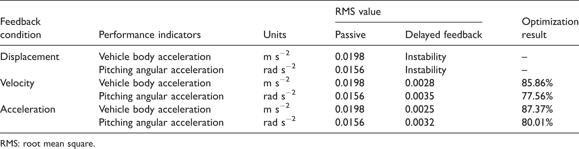
RMS: root mean square.
Conclusions
In this paper, choosing the different feedback strategies of the engine on displacement, velocity, and acceleration in the five-degree-of-freedom half-vehicle model under idling condition, there are different vibration effects. Compared with the passive feedback, reasonable feedback parameters in the active suspension with delay control can significantly reduce the response of the vehicle BA and PA and effectively optimize the suspension system and improve the vibration performance. When based on the engine acceleration feedback, the RMS of the accelerations is reduced, respectively, by 87.37 and 80.01% and the vibration characteristics are the best. All these results will provide a new theoretical basis and design reference for the development and research of suspension system.
Footnotes
Declaration of conflicting interests
The author(s) declared no potential conflicts of interest with respect to the research, authorship, and/or publication of this article.
Funding
The author(s) disclosed receipt of the following financial support for the research, authorship, and/or publication of this article: The supports of the National Natural Science Foundation of China (Grant No. 51275280) and Shandong Province Natural Science Foundation of China (Grant No. ZR2015EL048) are much appreciated.