
Abstract
Gear system is characterized by high efficiency, compact structure, and transmission ratio stability, and it has been extensively applied in various industrial equipment. This paper presents a novel preliminary estimate method for gear reducer noise radiation and vibration characteristics, and systematic researches on radiation characteristics of gear reducer are made. In the noise analysis process, the influence of time-varying mesh stiffness, error excitation, and tooth flank contact feature are comprehensively considered, the linear vibration model and nonlinear vibro-impact model for transmission system is set up, and then the dynamic load of the gearbox is obtained by solving the model. The dynamic load of bearing is taken as an excitation, the finite element method/boundary element method is adopted to analyze vibration and noise radiation characteristics of the gear reducer. The time domain response and field point noise spectrum at sound field are obtained, and the influence of harmonic components in excitation on vibration noise radiation of gearbox are discussed. The dynamic characteristics and sound radiation characteristics of gear reducer under different operating conditions are calculated, the change pattern of frequency component of the bearing dynamic load and noise radiation based on operating condition are obtained, and some interesting conclusions are observed from research that the gearbox produce the linear vibration and noise under the heavy load condition. Meanwhile, the nonlinear vibro-impact and noise is appeared under light load condition. The distribution of the gearbox radiated nose is uniform in various conditions, but noise takes sub-harmonic components as fundamental frequency and more peaks in the noise spectrum are observed. With the increase of the rotary speed, the noise tallies with the trend described by Kato formula except that under the gear system resonance speed. The impact force between teeth flanks shall be on the increase with the increase of rotary speed, and gear pair vibration experiencing a course from irregular vibration to regular periodic rattle vibration. With the increase of load, the noise of reducer changes with load as the variation of logarithmic function. For the noise in the process with load on the increase from no-load (the load is 0), the gear reducer vibration condition experienced both sides collision, single-side collision, and normal meshing in three stages. The radiated nose is increased gradually, but the abrupt change happened in critical positions between both sides collision and single-side collision as well as single-side collision and normal meshing in the process. The conclusions of this paper will offer theoretical basis for reducer to reduce vibration and noise.
Introduction
Gear system is characterized by high efficiency, compact structure, and stable transmission ratio, having been widely applied in various industries. During the operational process, under the action of inevitable meshing stiffness and error excitation, gearbox vibration is generated. The strong vibration of gearbox is not only adverse to stability of system but also radiates noise to outer space, resulting in noise pollution and affecting the operation of equipment in terms of comfort. Accordingly, vibration noise of reducer has attracted more and more attention.
Noise control level of gear mechanism is not only to embody comprehensive strength of a manufacturing enterprise, but also subjected to environmental law and regulation. Therefore, reducing the noise of reducer has been a major problem to be solved in this field. The research of gear reducer vibration and noise began a century ago; however, vibration noise as a major factor to evaluate performance of a mechanism began in the middle of 1960s. In early stage, based on much research of experiments and tests, scholars obtained empirical formula for estimating noise intensity of gear pair.1–3 The appearance of numerical methods (such as finite element method (FEM) and boundary element method (BEM)) has substantially supported research of reducer’s vibration and noise. The FEM/BEM method is the prevailing method applied to the numerical analysis for the reducer vibration and noise. Abbes et al. 4 adopted structural-acoustic coupling method to analyze acoustic radiation of the simple gearbox structure under the action of time-varying stiffness excitation. Kato et al. 5 made a study to analyze the vibration and noise radiation of single-stage gearbox by using the FEM/BEM method. The effectiveness of the FEM/BEM method is proven through comparing the analysis results with test results. 5 Yinghou et al. 6 adopted the FEM/BEM method to analyze the vibration noise of the planetary gear reducer, and then the accuracy of the theoretical analysis method was verified. Tuma 7 analyzed major excitation component, and a new method was presented to reduce the vibration and noise through optimum gear geometry and gearbox stiffness. Lu et al. 8 considered the effect of internal excitation in gear system to analyze the dynamic characteristic of marine gearbox in rated operating condition. Sellgren and Åkerblom 9 analyzed the dynamic response of gearbox discussing the influences of various bearing connections on the dynamic response.
According to the vibration characteristics, the gear reducer vibration may be divided into gear whine noise and gear rattling noise. Gear whine noise means gear vibration produced by the action of time-varying meshing stiffness and error excitation, then it is transmitted to gearbox by transmission system (shaft and bearing) resulting in noise radiation. 10 Gear rattling noise means repetitive impact (contact, separation, and contact again) between gears due to backlash in light load and high-speed condition, resulting in intense vibration and noise radiation. 11 Barthod and Hayne 12 described gear rattling principle in a more intuitive way, indicating that rattling vibration noise shall intensify with the increase of frequency and amplitude of excitation. Dogan et al. 13 showed that the influencing factors of reducer rattling noise contains geometric parameters (such as module, number of teeth, helical angle, backlash, etc.) and operating parameters (such as angular acceleration, excitation frequency, etc.). Younes et al. 14 took impact load into consideration, and his research showed that the gear rattling is also an effect with coefficient restitution for impact (related to structural material, contact shape, and lubrication state). And now, there have been few documents with focus on research of transfer process between gears impact vibration and mesh vibration for gear reducer.
This paper presents both the linear vibration model and impact model of gear transmission system set up by using the lumped mass method. Taking bearing dynamic load of the gearbox as excitation, the FEM/BEM method is used to analyze the vibration and acoustic radiation characteristic of the reducer, and the dynamic characteristic and acoustic radiation characteristic of the gear reducer in various operation conditions are researched.
Vibration noise analysis process
Calculation method of dynamic excitation of gear reducer
In the meshing process, the dynamic gear excitation is transmitted to gearbox causing vibration of gearbox, and therefore proper solution to dynamic excitation of gear meshing is the key to solve the radiation noise of gearbox. Duan et al.
15
and Tengjiao et al.
16
presented a simple way to synthesize dynamic excitation in gear, as shown in the following equation

It is a convenient method to calculate the internal excitation of gear, but it cannot figure out the influence of flexible component such as shaft and bearing of the system.
Computational multi-body dynamics is a theoretical method to research complex mechanical system in terms of statics, kinematics, dynamics, and control system analysis. Many scholars have adopted multi-body dynamics to simulate contact process of gear teeth. Zhou et al. 17 set up multi-body dynamic model for vehicle transmission system, in which the Hertz contact theory is adopted to simulate gear meshing process, then the forced torsional vibration under the accelerating condition is carried out to verify that multi-body dynamic method is able to truly reflect inherent characteristics of the system. In order to reflect gear flexibility better, Ebrahimi and Eberhard 18 introduced elastic elements between gear teeth and gear body along the tangential direction of circumference, and then the gear rigid-flexible coupled multi-body model was set up. Multi-body dynamic method has unique advantage to simulate the characteristics of gear transmission system in terms of kinematics and dynamics. However, gear teeth in a majority of the existed models are considered as rigid body. Meanwhile, this method is not easy to reflect the effect of the gear’s error effectively.
In order to induce the action of gear’s dynamic excitation with a proper way, the paper adopts gear system dynamics to solve dynamic excitation of gearbox. Gear system dynamics studies the dynamical behaviors of gear system in power transmission and operation process, and its research areas include dynamic meshing force, dynamic load coefficient, vibration and noise characteristics. Tuplin put forward the first type of gear dynamic model 19 in 1950, and then researchers started to take more parameters (such as gear error and time-varying meshing stiffness) into models. The acoustic response can be obtained truly by the calculation of the equivalent dynamic model with the consideration of the dynamic characteristics of the system and proper excitation component.
In addition, with the development of gear system dynamics, various gear excitations and relevant influencing factors are constantly integrated in system model, with the gear system dynamics developing from linear dynamics into nonlinear dynamics gradually, and time-invariant system develops into time-varying system. So gear system dynamics becomes a foundation for more actual simulation of transmission system vibration and calculation of dynamic excitation of gearbox.
Vibration noise analysis method of gearbox
In the sound field analysis process by using the BEM, it is necessary to take normal vibration acceleration on structure surface as boundary condition, which is obtained by other numerical methods (such as FEM) or test. The vibration noise analysis method for the gear reducer is as shown in Figure 1, the whole analysis process is composed of four parts namely, the gearbox dynamic excitation calculation, gearbox vibration analysis, boundary element model building, and acoustic radiation analysis.
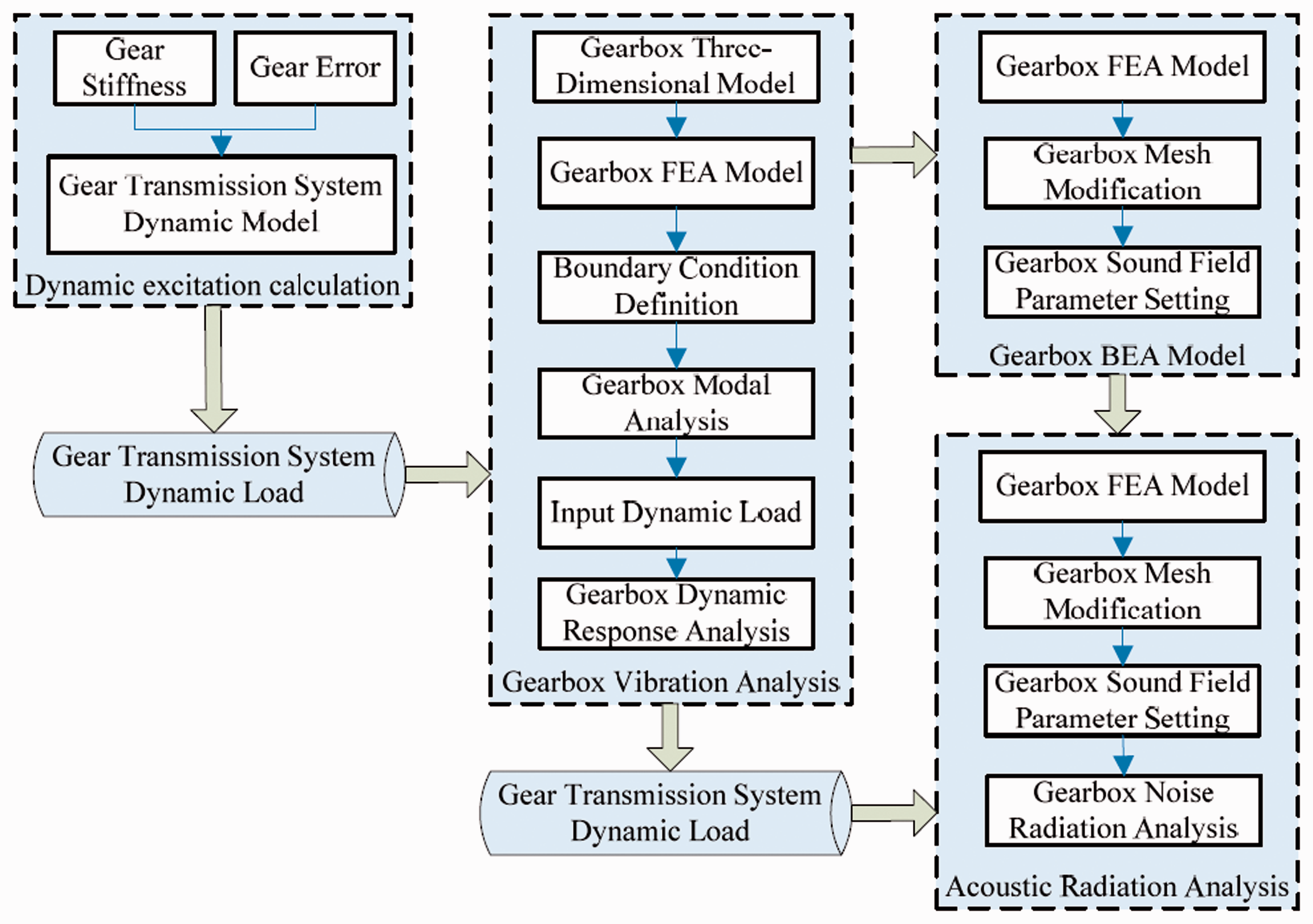
Analysis process of noise radiation of gearbox.
Gearbox dynamic excitation calculation
Analytical model is established by using lumped mass method. In the model, the influence of the time-varying meshing stiffness, gear error, and flexible support of shaft is considered. Then the dynamic load of bearing and inherent characteristic of transmission system are obtained through calculate the system model. Finally, the dynamic load should be exported for the calculation of the dynamic response of gearbox.
Gearbox vibration analysis
According to the gear reducer assembly relation, boundary condition should be applied to gearbox FE model. With gearbox modal analysis, the natural frequency and vibration mode are obtained. Then dynamic load of the bearing is imported and applied on the gearbox FE model. In order to reduce the computing resource, the mode superposition method is used to solve the dynamic response of the gearbox structure. Lastly, the vibration acceleration of the gearbox surface is obtained.
Boundary element model building
The gearbox FE model is used to set up acoustic boundary element model as follows: extracting the surface elements of gearbox FE model, and then filling up the hole (such as bearing hole, bolt hole) on the surface of the structure by using shell element. Finally, the gearbox boundary element model is obtained by remeshing the surface elements of gearbox.
Acoustic radiation analysis
In this process, the fluid (in this paper is air) attribution of outside gearbox should be defined, and field point (the key point in sound field forobserving) of gearbox sound field must be picked out. Then transfer vector between vibration of gearbox surface and sound field is built. Taking normal acceleration of the gearbox surface as boundary condition to analyze noise radiation of gearbox, the acoustic response at every field point is obtained.
With using the above mentioned process, the gearbox vibration and noise radiation shall be able to solve.
Gear transmission system dynamic model
Three-dimensional model of gearbox
The object of analysis in this paper is a single-stage gear reducer, whose model is as shown in Figure 2, which is a single-stage straight toothed cylinder gear reducer, and the minor chamfering and feature in structure is simplified in the model.
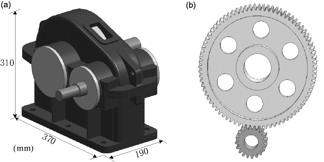
Gear reducer model: (a) assembly mode of the reducer; (b) gear pair model.
The parameters of gear transmission system area are as shown in Table 1.
Parameters of the analytical model.

Building of lumped mass model for transmission system
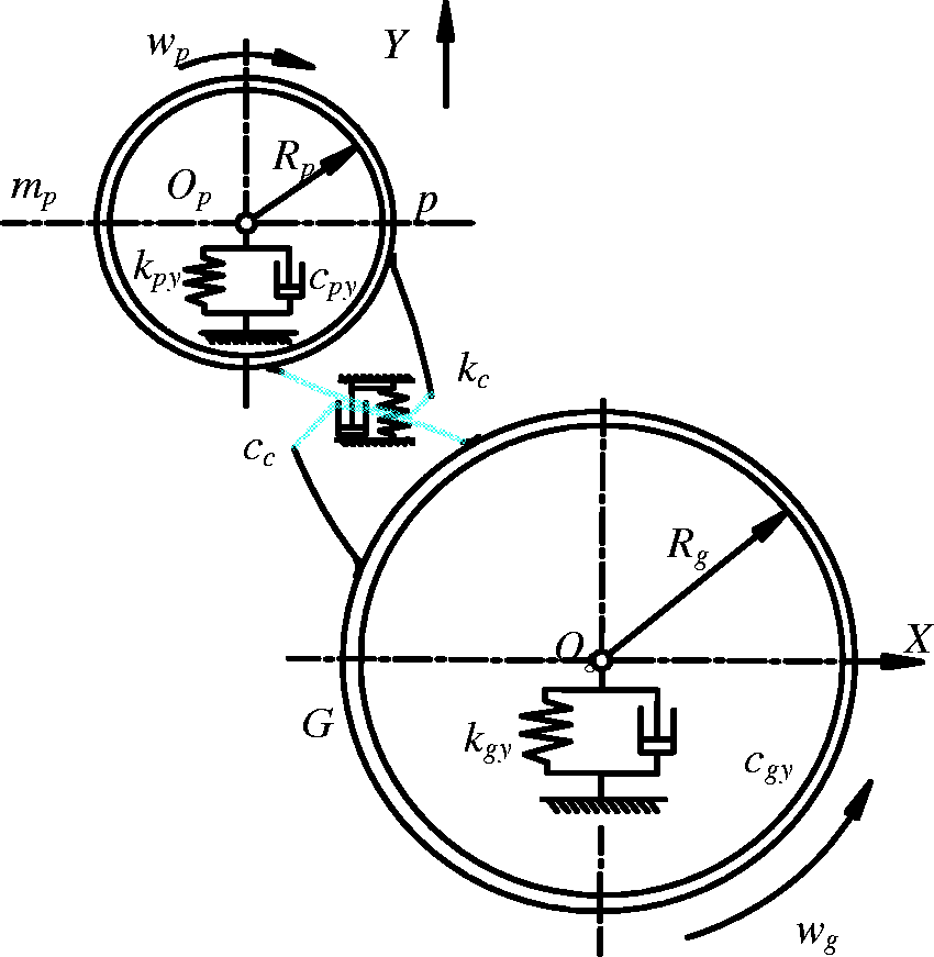
In case the gear pair is under heavy load condition, two tooth flanks of gear pair in the meshing process may keep contact all the time, and it is advisable to adopt lumped mass model to set up gear transmission system dynamics model. The action of friction force is not considered in modeling, the component which have large elasticity but smaller mass (such as shaft, bearing) in transmission system is simplified into spring structure, and the component which have larger mass but lesser elasticity (such as gear) therein is simplified into mass block. The dynamical model for straight cylindrical gear pair is shown in Figure 3, in which p is the drive gear, g is the driven wheel, and Y is the direction of action line. In the model, the vibration mode of the transmission shaft is not considered, and therefore support stiffness and damping for shaft, bearing, and box are indicated by combined constant values: kpy and kgy as well as cpy and cgy.
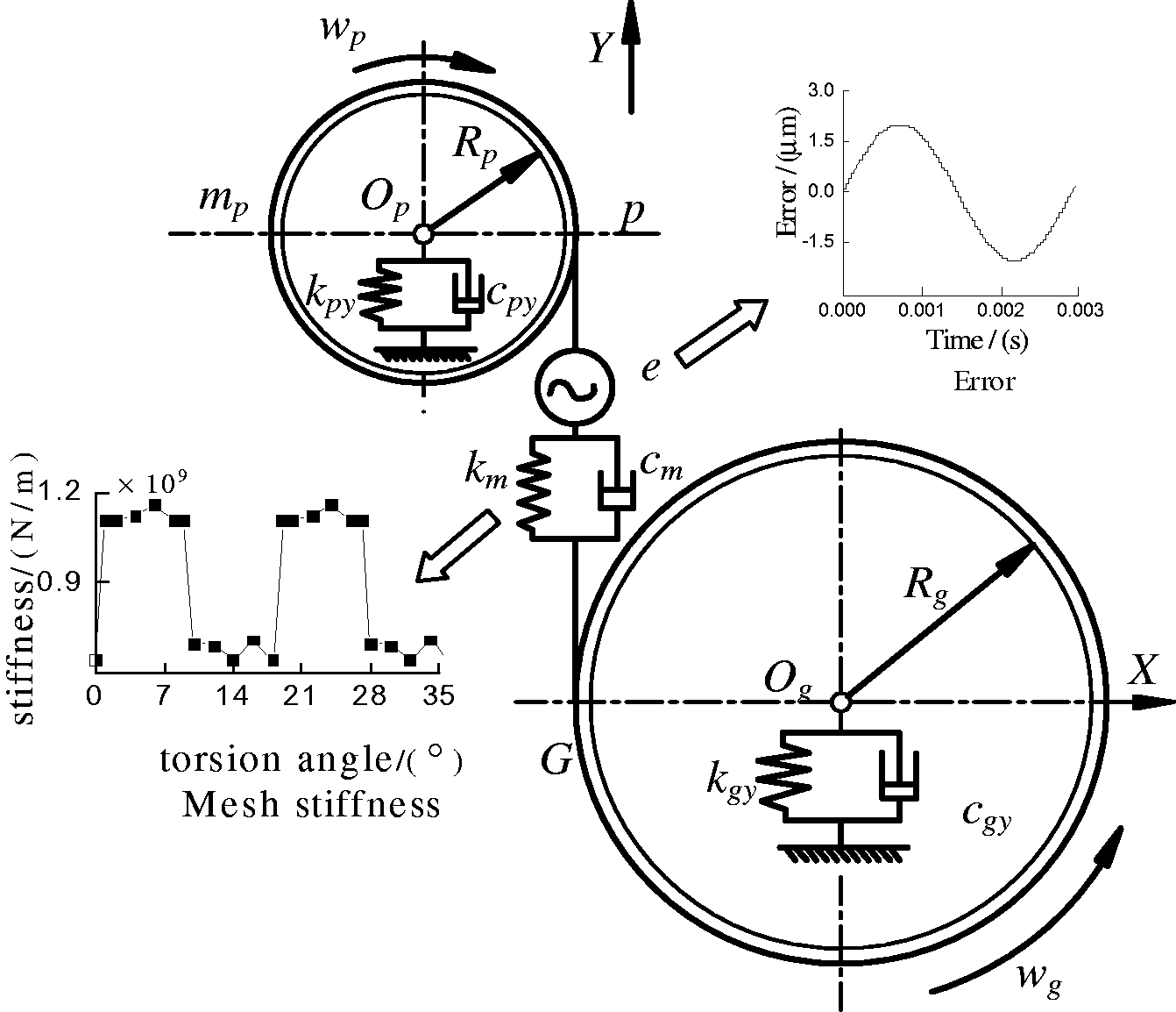
Dynamic model for gear pair.
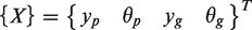
It is observed that the dynamic meshing force is along the direction of gear pair action line, therefore, the model has four degrees of freedom (DOF), namely rotation DOFof driving and driven wheels, the translation DOF along Y direction. Then the generalized displacement vector of system may be expressed as
Meshing force and damping force for meshing of gear pair may be expressed as follows
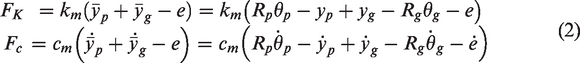

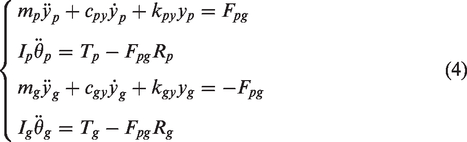
According to the loading condition on every part, the differential equation of the system is obtained as
Building of impact model for gear pair
In case the transmission system is under lighter load or no-load condition, the gear pair cannot always keep contact, and therefore the driven gear accelerates instantaneously and separates from the driving gear in such a reciprocating way.
20
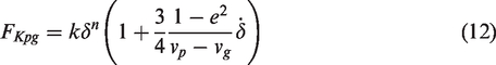
In this process, the gears produce the impact force by mutual impact between gear teeth, and the paper adopts Hertz contact mechanics to describe elasticity between contact surfaces. At this point, the acting force of gear pair is no longer Fpg as shown in equation (3), and it is necessary to rebuild impact model for gear pair as shown in Figure 4, in which two tooth flanks of gear pair are connected by contact spring,
Impact model for gear pair.
It is observed from two gear teeth in gear impact process that the mutual collision has normal direction on the contact surface in the direction of path of contact, and the generalized Hertz formula is given as follows


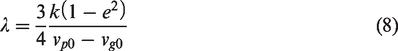
And, in order to determine the relation of hysteresis damping coefficient 
Recovery coefficient and hysteresis damping coefficient satisfy
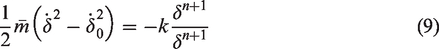
In case that the speeds before and after impact are known, the maximum amount of indentation deformation δ
m
and contact time are determined, the motion equation for two masses at compression stage is
The above-mentioned formula is subject to integral at compression stage, then
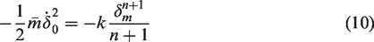
So as to solve out
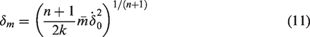
The contact force is equivalent to
The above mentioned formula reveals relation among contact force and recovery coefficient as well as speeds before and after impact.
Analysis of vibration noise of reducer
Dynamic characteristics of the reducer
Analytical model for gearbox vibration is set up by using finite element method, as shown in Figure 5, the model is meshed by tetrahedral element, with 38,634 nodes and 146,238 elements. The material for gearbox is cast steel, modulus of elasticity E = 207 GPa, Poisson’s ratio υ=0.3, density ρ=7800 kg/m3. Dynamic load acting on output and input shafts are transmitted to gearbox by bearing, so we built the central nodes in the bearing hole, and coupled the central nodes and surface nodes of the bearing hole. Then dynamic loads are applied on the central nodes. The semispherical sound field is set up in the place 1 m away from center of gearbox. For calculation, the sound speed is taken to be 341 m/s, air density 1.21 kg/m3, and step pitch 10 Hz.
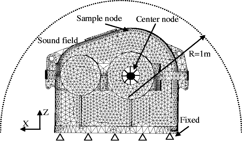
The gearbox FEM model.
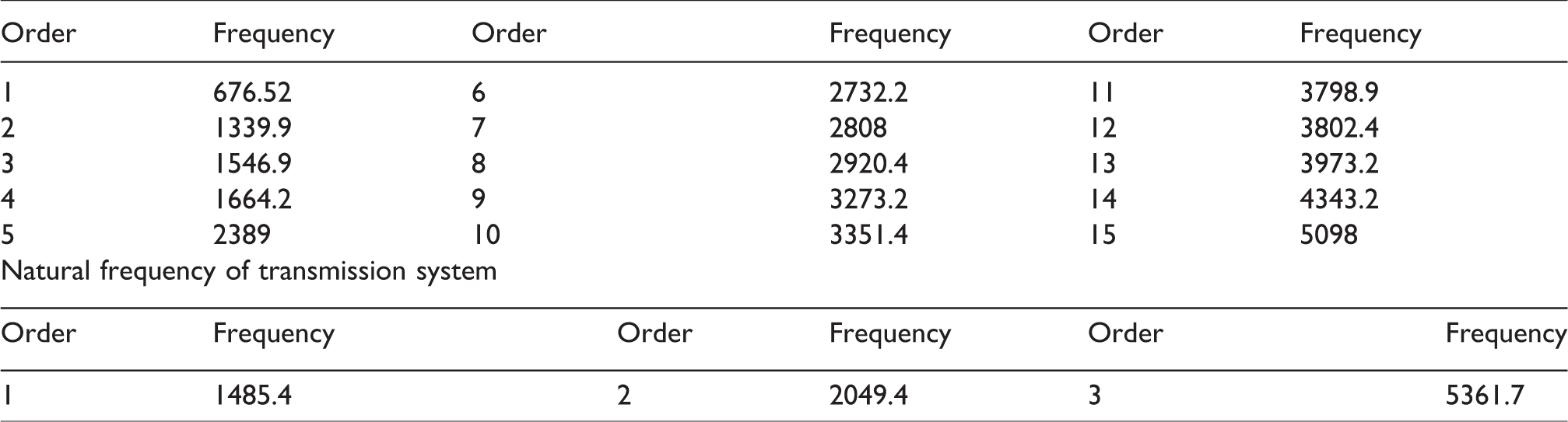
The Lanczos method is adopted to carry out modal calculation of gearbox, and the natural frequencies of gearbox are shown in Table 2.
The gear reducer natural frequencies (Hz).
The first eight natural vibration modes of the gearbox are shown in Figure 6, and since the lower part of gearbox is restricted, its vibration amplitude is smaller, but the vibration on the upper part of gearbox is more intense. The first-order mode of vibration is horizontal swaying on the upper part of gearbox; the second order and the sixth order show torsional vibration, with input end and output end of gearbox experiencing horizontal vibration respectively and without vibration in the middle of gearbox; the third-order mode of vibration is the axial vibration on bearing pedestal at output end; the fourth-order and the fifth-order modes of vibration are swaying on front end and rear end of the upper part of gearbox, the seventh order and eighth order are complex mode of vibration.
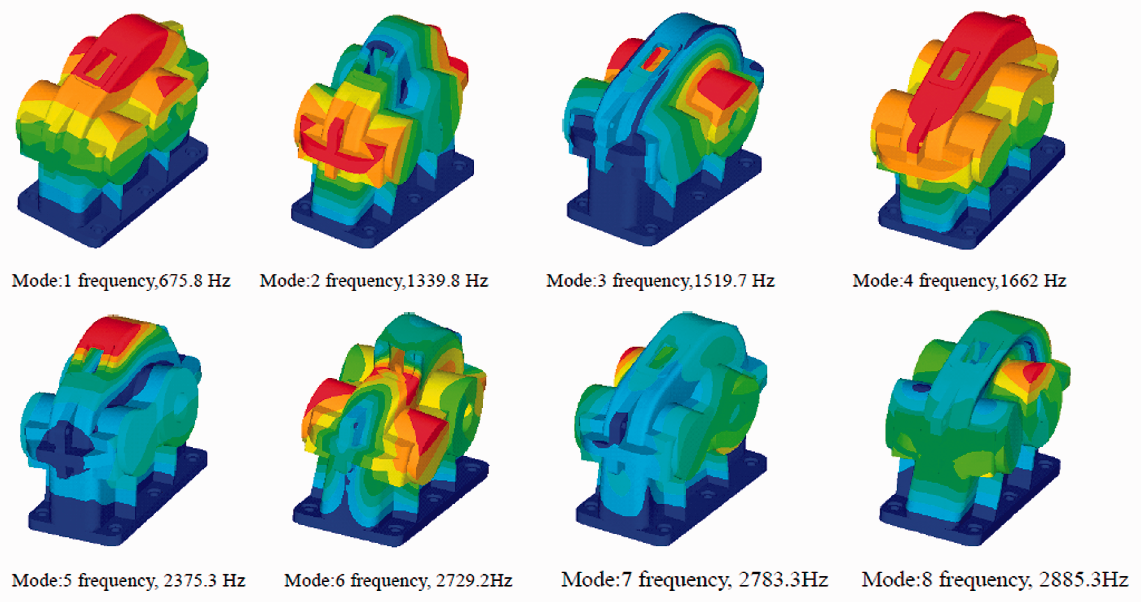
Mode of vibration of gearbox.
We developed the calculation method for solving the dynamic response of structure (solution process is as shown in Zhou and Wenlei 21 ), and then the normal vibration acceleration on the external surface of gearbox is taken as boundary, and BEM is adopted to solve the noise radiation of gearbox.
Noise radiation of gear reducer under heavy load condition
When input power is 10 kW and rotary speed is 1000 r/min, Newmark time domain integral method is adopted to solve the model, and then the dynamic force of bearing is obtained as shown in Figure 7. It is observed that the main frequency components of the bearing load at input end are 3-times, 4-times, 5-times, and 6-times frequency of meshing frequency (333 Hz) of gear pair, in which 5-times frequency component is the largest in energy.
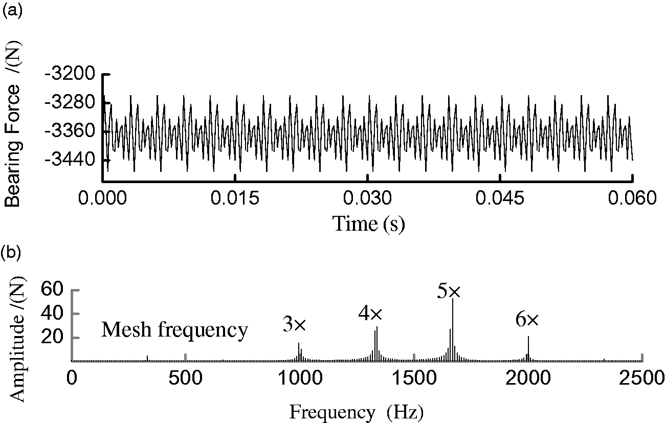
Dynamic load on the pinion bearing: (a) the time history of dynamic pinion bearing force; (b) frequency spectra of dynamic pinion bearing force.
Hemispherical sound field is defined outside of the gearbox and is shown in Figure 5. Three representative field points are selected in the sound field, which are located at the top of the gearbox (field point a), and the left and right sides of the gearbox (field points b and c). The frequency response of sound pressure level is shown in Figure 8.
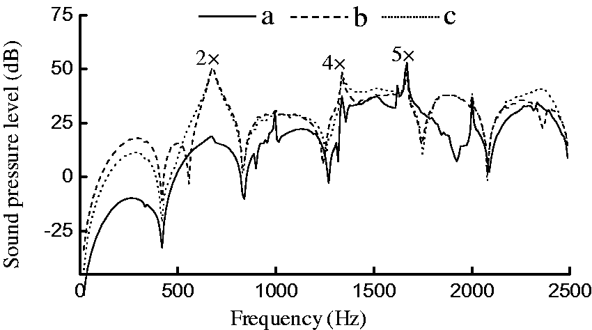
Noise spectrum of gearbox at different sound field points.
Since most of the mode shapes is torsional, vibration and normal vibration on top of the gearbox is not so intense, therefore, the noise on the top of the gearbox is obviously smaller than that on both sides (right side and left side); the field points on the right and left sides are in symmetric distribution, so the sound pressure level of the both sides are basically equal. From the sound pressure level curve, we can find that peak values are generated in the position of 2-times, 4-times, and 5-times of meshing frequency. Since first-order natural frequency (676.52 Hz) of gearbox is closer to 2-times frequency (666 Hz), and its mode shape is sway on both sides, the noise in the position of twofold frequency is significantly larger than that on both sides of the gearbox. With larger energy in the fourth and the fifth harmonic components, accordingly, apparent peak value is generated in the positions of 4-times frequency and 5-times frequency. It is obvious that the radiated noise of gearbox is not only under the influence of dynamic characteristic of gearbox structure but also associated with the dynamic characteristic of transmission system and transmission of vibration.
Noise radiation of gear reducer under light load condition
When the rotational speed of the driving gear is 1000 r/min, and no load is applied on the driven gear, the vibro-impact phenomenon is observed in the gear pair. In this process, the tooth flank of driving gear collide with the driven gear to make it rotate. However, since the load is small, the drag torque is smaller than the inertia torque produced by impact, then

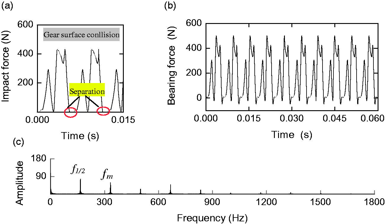
Impact force of gear pair is as shown in Figure 9(a). Tooth flank of the driving gear is unable to keep in contact with the driven gear all the time, firstly the driving gear collide with the driven gear and make the acceleration of the driven gear to increase rapidly, then its speed exceeds the driving gear in a second. The separation of the driven gear and driving gear occurs due to backlash, the two gears have no interaction force in the process, as shown at point A in Figure 9(a). Subsequently, since speed of the driven gear is faster than the driving gear, the tooth flank of the driven gear approaches the tooth back of the driving gear and make tooth back collide again. At this moment, the speed of the driven gear is reduced rapidly, which is lower than the speed of the driving gear, and tooth flank of the driven gear is separated from tooth back of driving gear again as shown at point B in Figure 9(a). Finally, the tooth back collision between the driven gear and the driving gear occurs again, thus, the gears experience a complete vibro-impact period. After the gear pair is in steady operation, dynamic load is gradually in periodic distribution, as shown in Figure 9(b); however, gears vibro-impact period is much longer than the meshing period of the gear pair, and the instantaneous impact effect will appear on the bearing load at the moment of separation and impact between gears are happened.
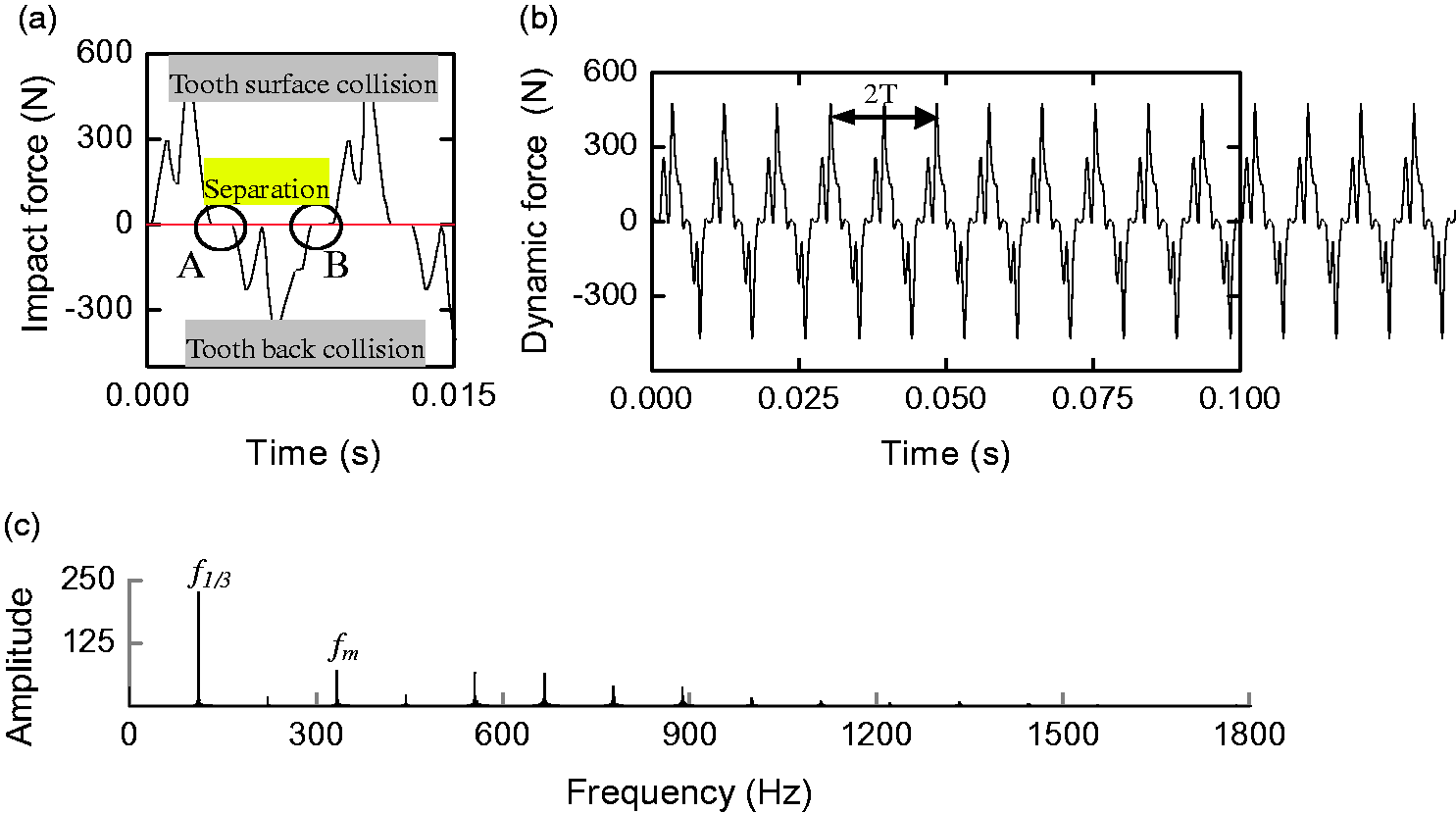
The bearing dynamic load of the gear system: (a) impact force time history; (b) bearing force time history; (c) bearing force frequency spectrum.
The frequency spectrum for noise.
Dynamic load frequency spectrum of the gear pair is as shown in Figure 9(c), and it is observed that there is 1/3 sub-harmonic component in the frequency spectrum, which is the major frequency component. Relatively, meshing frequency component and its multiple frequency components are not, obviously.
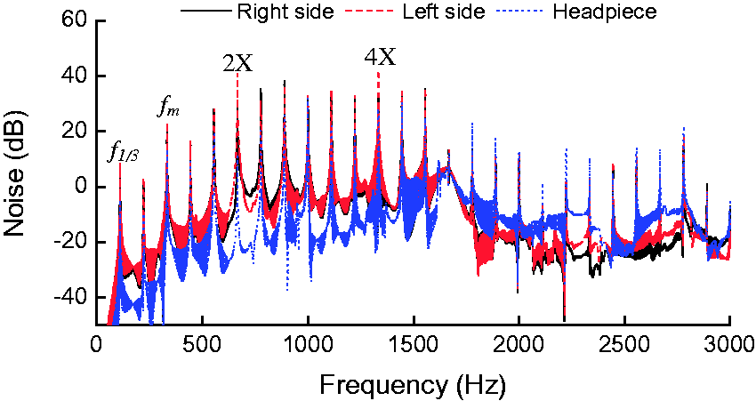
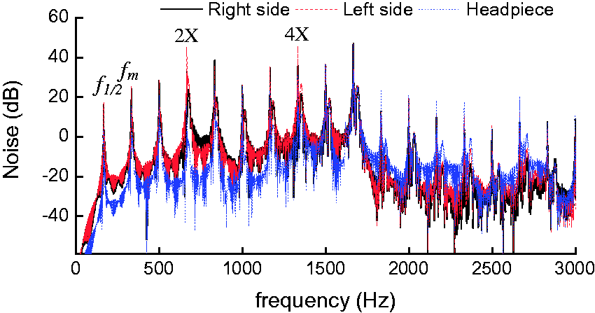
Gearbox noise spectrum obtained by calculation based on the BEM under the excitation of the dynamic load of bearing is as shown in Figure10. It is observed from the noise distribution that the noise around the gearbox is consistent in distribution, the noise on the top field point much lower than that on both sides. Meanwhile, the entire noise intensity is obviously reduced, and the noise on the top appearing in the position of 2-times of mesh frequency (777 Hz) is 37 dB. The field points on both sides of bearing are in symmetric distribution, with peak values generated on the positions of 2-times, 4-times, and 5-times of the mesh frequency, and the maximum peak value generated on the position of 2-times and 5-times of the mesh frequency being 44 dB. Since excitation components are more intensive than that under heavy load, there are more peaks appearing in the noise spectrum, the noise curve take 1/3 sub-harmonic component as fundamental frequency and the interval between the neighboring peaks is the fundamental frequency.
Although 1/3 sub-harmonic component is prevailing in the bearing load in low-frequency area (lower than 500 Hz), gearbox has no natural frequency in the frequency domain and, therefore, the gear noise in the area is lower. There are not only more excitation components but also several natural frequencies distributed in the intermediate frequency domain (500–1500 Hz) for gearbox and, therefore, the noise in the area is higher obviously.The excitation and noise are decreased respectively in high-frequency area (more than 1500 Hz).
Influence of operating condition on noise radiation under heavy load condition
Influence of rotary speed on noiseradiationunder heavy load condition
Vibration excitation of reducer is primarily composed of meshing frequency and its multiple frequencies; in addition, the relation among every excitation component and transmission system natural frequency also has direct effect on the vibration amplitude.
Waterfall of speed-dependent noise within the range of rotary speed from 500 r/min to 3000 r/min is as shown in Figure 11, in which dark-colored area indicates position with intense noise radiation. It is observed that every frequency component in noise spectrum at low rotary speed is small, and with the increase of rotary speed, the noise radiation is increased.
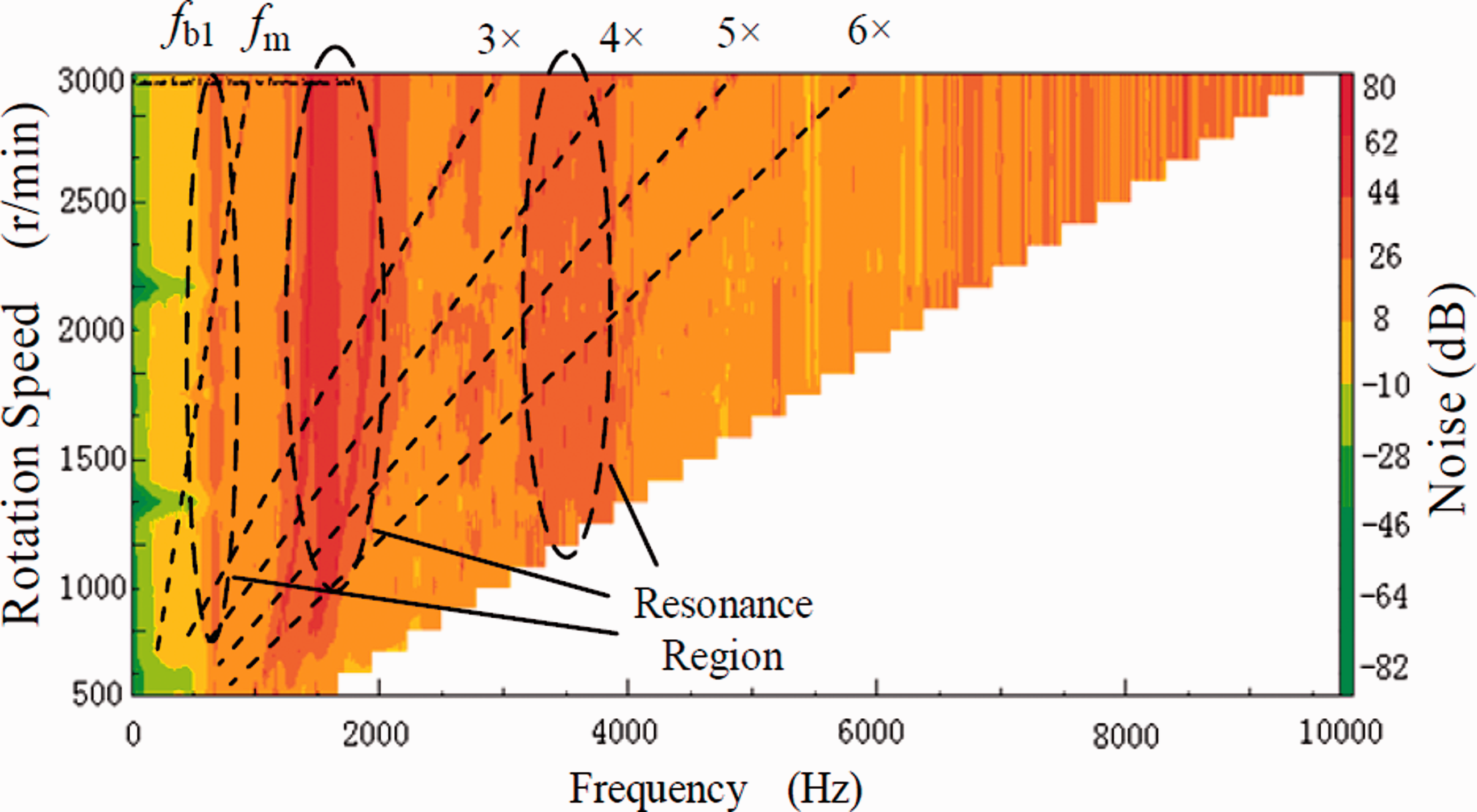
Waterfall of the gearbox radiated noise.
It is observed that radiated dark-colored area is generated at meshing frequency and its multiple frequencies, but it is not obvious. The more intense noise is appeared in the frequency range of around 670 Hz, 1300–1700 Hz, and 3000–4000 Hz, due to which they are close to the natural frequency of gearbox. The higher vibrational energy is produced due to the second-order, the third-order, and the fourth-order natural frequencies of gearbox being more sensitive to excitation, and intense resonance is generated in this frequency band at every rotary speed.
In addition, although gearbox vibration energy is smaller in the frequency range of 3000–4000 Hz, the normal vibration is more intense, therefore, noise radiation in this frequency band is also intense and such noise distribution pattern is also found in the vibration and noise research of gear reducer by Jolivet et al. 22
The effective sound pressure level of the gearbox radiated noise is calculated under the increased speed condition. The relation between the effective sound pressure and line speed of the gear addendum is as shown in Figure 12, in which curve a is a result of the numerical calculation, curve b is the result calculated by Kato formula. Since Kato formula fails to embody natural frequency of the transmission system, the changing trend of the result dependent on linear speed of gear addendum is smooth, and the noise of reducer is increased with the increase of rotary speed. 3 Calculation by FEM/BEM is not only to take dynamic characteristics of the gear reducer into consideration, therefore, the noise curve is fluctuant to a certain extent. In case of 750 r/min, since the 6-times gear frequency component in the excitation is closer to the first-order natural frequency of the transmission system, the transmission system generates larger vibration, and making noise radiation curves a and b deviate from d1=7 dB; in case of 2100 r/min, since 2-times component (1398 Hz) of meshing force is closer to the second-order natural frequency of gearbox, it results in larger vibration in gearbox making noise radiation deviate from d2=5 dB, if the two resonance positions are not considered, the deviation of two curves in other positions is within 3dB, accordingly, and it is observed that results of simulation calculation and results of calculation by Kato are consistent.
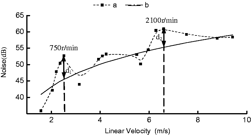
Change in the noise radiation of gearbox dependent on the linear speed of gear.
Influence of load torque on noise radiation under heavy load condition
For the noise radiation of the gear transmission system, load torque does not change the distribution of the exciting frequency component, and it only influences the amplitude of the frequency component with linear pattern. The noise spectrum of the reducer under three types of load condition (T under rated operating condition, 0.5×T and 3×T) is shown in Figure 13. With the increase of load, the peak value of every frequency of reducer noise is on the increase.
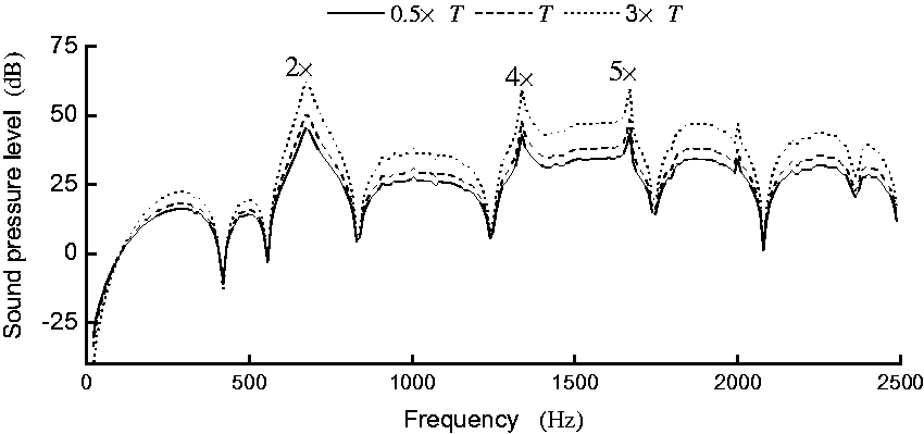
Noise spectrum of gearbox under various loads.
The effective sound pressure level is calculated as shown in Table 3.
Effective sound pressure level under various loads (dB).
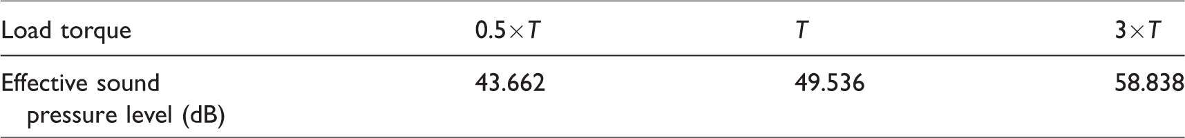
In case the rotary speed is constant, the change of radiated noise and load torque conforms to the conclusion that reducer noise and 20logW are in proportion drawn by Niemann and Kato
3
namely

Influence of operating condition on noise radiation under light load condition
Influence of rotary speed on noise radiationunder light load condition
In order to know the influence of rotary speed on noise radiation of gear pair under light load condition, the impact force at rotary speed from 100 r/min to 1000 r/min is calculated under no-load condition. Waterfall of impact force at every rotary speed is shown in Figure 14.
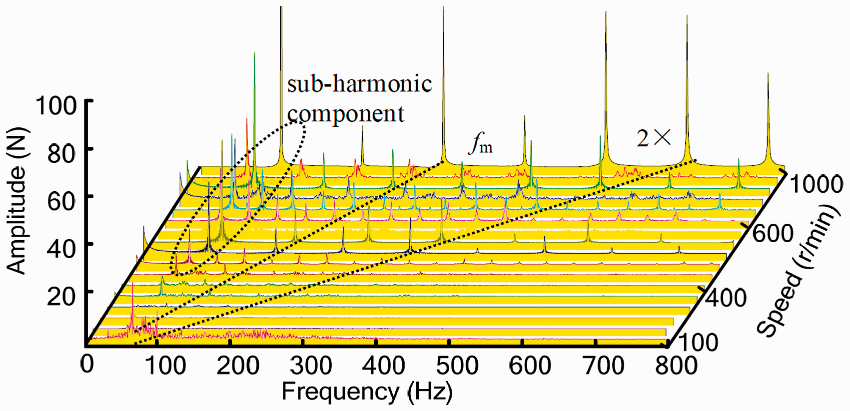
Waterfall of impact force at every rotary speed.
Relatively speaking, there are more frequency components appeared, when the gear pair is working under the vibro-impact stage. Although the meshing frequency components and the multiple frequency components still exist, they are not major excitation component, and the distribution of the major frequency components are found to be intricate. In case of low rotary speed condition, the gear pair also shows tooth separation and tooth back impact phenomenon, and there is no apparent regular fluctuation observed in impact force, with the sub-harmonic components and meshing frequency components as major frequency component in frequency spectrum. In addition, there are a great amount of successive frequency components (such as 100–400 Hz) in the dynamic load frequency spectrum under the low rotary speed condition. In case the rotary speed is more than 500 r/min, sub-harmonic frequency component appears, and its peak value is found to be higher than that of other frequency components, including 1/2 harmonic component at 500 r/min, 1/5 harmonic component at 600 r/min, 1/3 harmonic component at 1000 r/min, etc.
It is observed from the radiated noise of gearbox that the relative speed between the gear teeth of the driven gear and the driving gear is increased, so the fluctuating amplitude of impact force is obvious, as shown in Figure 15. In case of low rotary speed (lower than 500 r/min), the relative speed between tooth flanks is lower, therefore, the fluctuating amplitude of impact force is smaller. The major frequency component of the excitation is slight, and a great amount of low energy frequency components appeared disorderly at the same time. With the increase of rotary speed, its increase trend is moderate. When the rotary speed is in high condition (higher than 500 r/min), the larger impact force is produced, and the major frequency component in excitation is more regular. The vibration of the gear pair shows apparent regularity in this stage, and the intensity of the vibrations is increased rapidly with the increase of rotary speed.
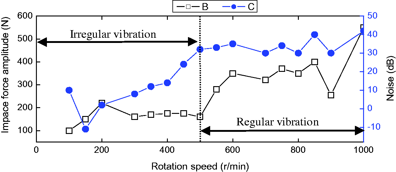
Change in the amplitude of impact force and load at every rotary speed.
Waterfall of gearbox noise under no-load condition is as shown in Figure 16. We can see that there is no apparent regular change in distribution of radiated noise, but larger vibration energy appears in the frequency range from 1600 Hz to 1700 Hz due to the fourth-order natural frequency of gearbox being sensitive to the excitation. Therefore, it is similar to the noise of the reducer under the heavy load, and the gearbox at every rotary speed also generates intense resonance and noise in this frequency band under light load conditions. When the input speed is low, the impact force is small and the frequency component of the excitation is disorderly, so the noise is small with no zonal distribution of intense noise in the noise spectrum distribution. After rotary speed is up to 500 r/min, the noise of reducer enhances obviously and the intense noise area appears at intervals of sub-harmonic frequency.
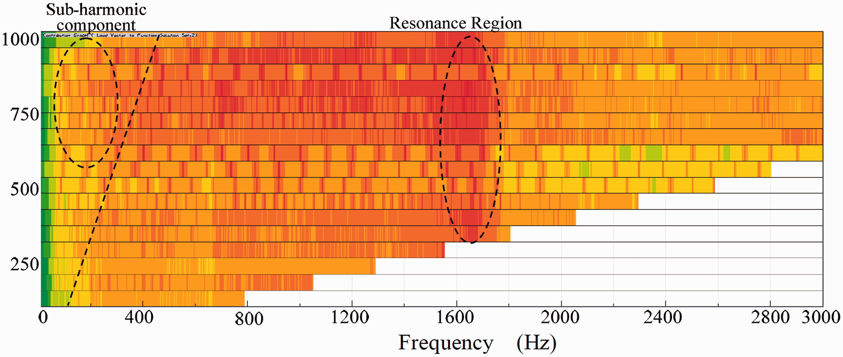
Waterfall of reducer noise under no load.
Influence of load on noise radiation under light load condition
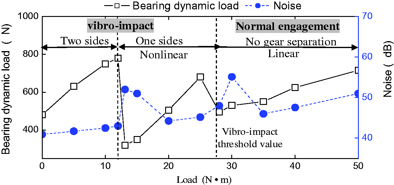
Load have a direct influence on the meshing state of gear pair, and this paper figures out the changing trend of the dynamic load and radiated noise of gearbox with the increase in load as shown in Figure 17, and it is observed that gear pair experiences a greater fluctuation in the process with load from 0 to 50 N·m at 1000 r/min. When the load is more than 28 N·m, the tooth separation and impact phenomena is disappeared, so the 28 N·m can be considered as the threshold for gear pair impact. The gear impact phenomena also can be divided into two stages namely tooth flank impact on both sides at 0–12 N·m and tooth flank impact on single side at 12–30 N·m.
Impact force of gear pair in the stage of impact on single side.
With the increase of load, the reducer radiated noise is increased, and sudden fluctuation occurs at the two critical load positions, which are status of impact on both sides changing to impact on single side and impact on single side changing to normal meshing.
Impact on both sides
In this stage, the load is smaller and the tooth flank impact and tooth back impact on the gear pair appeared alternately. The impact force is as shown in Figure 9. With the increase in load, the rotary speed of the driven gear will reduce after tooth back impact, and the relative speed between the driving gear and the driven gear will be increased under the action of load. Therefore, the amplitude of impact force on gear tooth flank is enlarged, and the radiated noise is also strengthened.
Impact on single side
When the load is more than 12 N·m, the gear pair no longer shows impact on both sides, only the tooth flank impact is occurred. The dynamic force of gearbox at the load is 20 N·m is shown in Figure 18 and it is observed that the front tooth flank of the driving gear collides with the tooth flank of the driven gear, which makes the driven gear to accelerate instantly, and then its rotary speed exceeds that of the driving gear, which makes the separation to appear between tooth flanks. With the driven gear undergoing a brief separation, the impact force of the gear pair is zero at this moment, as shown in Figure 18(a), and the bearing load is as shown in Figure 18(b). When the gear pair is in steady operation, dynamic force is gradually in periodic distribution, but the instantaneous impact is produced on the bearing when the gears are recontacted.
Dynamic load of reducer in the stage of impact on single side: (a) impact force time history; (b) bearing force time history; (c) bearing force frequency spectrum.
The dynamic force frequency spectrum is as shown in Figure 18(c), and it is observed that the 1/2 sub-harmonic component is appeared and it became the major frequency component. Relatively speaking, the meshing frequency component and its multiple frequency components are insignificant.
Noise spectrum of the gearbox is shown in Figure 19, where the main frequency components of the dynamic load is changed from 1/3 sub-harmonic components to 1/2 sub-harmonic components, and so the number of the peaks in the noise spectrum is decreased. The distribution trend of the noise remains unchanged, the maximum frequency component on top is 1665 Hz, its value is 44 dB, which is increased apparently compared with the stage of impact on both sides. The noise on left and rightof the gearbox is more intense in the frequency positions of 2-times, 4-times, and 5-times meshing frequencies, and the maximum noise is 45 dB.
Noise spectrum for gearbox in various positions.
As the vibration status of the gear train just changed, the main excitation components of the gearbox suddenly changes from 1/3 sub-harmonic component to ½ sub-harmonic component, the strong shock is produced, and therefore the gearbox noise suddenly increases to 52 dB as the load is 12 Nm. With the increase of load in this stage, the rotary speed of the driven gear is decreased gradually during the gears separation, which will intensify the impact between tooth flanks, so the noise is also on the increase.
Normal meshing
When the load is more than 28 N·m, gear tooth separation and impact vibration phenomena is no longer generated and the normal meshing is started. Suddenly, the main excitation component is changed from 1/2 sub-harmonic component to mesh frequency component, the strong shock and noise are produced and gearbox noise suddenly increase to 55 dB at 30 N·m. Then the noise is decreased quickly and the reducer noise radiation type is changed.
Conclusion
This paper presents a novel dynamical analytical model for gear reducer, taking dynamical load of bearing as excitation, and the FEM–BEM is adopted to calculate the acoustic radiation characteristic of gearbox. The influence of operating condition on noise radiation of gear reducer is analyzed and the conclusions are as follows:
The overall distribution of the noise is basically similar around gearbox, with the noise on the right and left sides higher than that on the top and peaks in the frequency spectrum generated on the positions of multiple meshing frequencies. Under condition, more peaks are generated due to the sub-harmonic components taken as the fundamental frequency components. With the increase of rotary speed, the noise of the reducer is always on the increase. Under heavy load condition, except for the resonance speed, the variation trend of the noise is in compliance with that described in Kato formula. Under the light load condition, the vibro-impact in gear pair shall experience a process from irregular vibration to regular impact, where the noise is increased gradually and there is no apparent regular change in distribution. With the increase of load, the noise radiation of reducer under the heavy load condition changes with load as y=20log(x) functional relationship. When the load is increased from zero, the gear pair vibration mode experiences three steps: there is impact on both sides, impact on single side and normal meshing. In this process, the radiated noise of reducer is on the increase, with sudden change produced in the critical position.
Footnotes
Acknowledgement
The authors are thankful to the Xinjiang University.
Declaration of conflicting interests
The author(s) declared no potential conflicts of interest with respect to the research, authorship, and/or publication of this article.
Funding
The author(s) disclosed receipt of the following financial support for the research, authorship, and/or publication of this article: This study was funded by the Chinese National Natural Science Foundation (51665054) and Opening Foundation of State Key Laboratory of Mechanical Transmissions (SKLMT-KFKT-201714).