Wave propagation characteristics are determined for smart laminated fiber-reinforced composite cylindrical membrane shells with different piezoelectric coupling effects. Wave motion equations are derived using the membrane shell model. By solving an eigenvalue problem, dispersion curves of the wave motion are obtained for different axial and circumferential wave numbers. The effects of piezoelectric coupling, fiber orientation, stacking sequence, and material properties of the host shell on wave behaviors are investigated. The results of this paper can be used for studies on dynamic stability of piezoelectric coupled laminated fiber-reinforced composite shell structures and in design of smart structures with the piezoelectric materials for the applications of damage detection and structural health monitoring.
Composite structures, due to their high specific stiffness and strength, are widely used in various engineering applications such as mechanical, civil, aerospace, marine, and offshore structures. Two main constituents of composite materials are the reinforcing fiber and the matrix. The reinforcing fiber is discontinuous, stiffer, and stronger, while the matrix is continuous, less stiff, weaker, and lightweight. The mechanical properties and performances of composite materials are superior than those of the constituent materials used independently.1 A composite laminate may be made up of stacked unidirectional fiber-reinforced carbon/epoxy, kevlar/epoxy, and E-glass/epoxy layers. Therefore, composite structures are stiff and lightweight with outstanding mechanical properties and performances. Composite structures may be subjected to high rate of frequencies due to working conditions. Thus, understanding dynamics and wave propagation characteristics of composite structures can help us to recognize the existence of any defects such as crack and delamination in their early steps of initiation.
The membrane shell theory, i.e. the most simplified shell theory, was introduced by Love,2 in which transverse shear forces, bending and twisting moments are assumed negligible. This model is usable to study thin-walled shells in which only the in-plane normal and shear forces are considered. Donnell,3 Flügge,4 Vlasov,5 and Sanders6 presented some research works based on this simplified model.
Dynamics and wave propagation characteristics of laminated composite cylindrical shells were determined in many research studies.7–16 Zhang10,11 used the wave propagation approach to analyze the natural frequencies of laminated composite shells. He investigated the effects of shell parameters and boundary conditions on the frequencies. Song and Ge12 used the three-dimensional finite element model to investigate the dynamic response of composite shells under axial explosive impact load in tunnel. Cao et al.13 studied the ability of the first-order and Reddy third-order shear deformation shell theories to obtain the vibroacoustic responses of laminated cylindrical shells with normal deformation in the high frequency range in comparison with a three-dimensional higher order shear deformation shell theory. Song et al.14,15 presented an analysis on free vibration of symmetrically and rotating cross-ply laminated composite cylindrical shells under arbitrary elastic boundary conditions. Numerical and experimental buckling behaviors of axially compressed, unstiffened carbon fiber-reinforced polymer (CFRP) cylinders with and without an additional lateral load were studied by Khakimova et al.16
The concept of smart structures is known for their application in areas of engineering other than mechanical engineering that can withstand a significant range of mechanical environments with no failures and acceptable stiffness. These materials, due to the properties and behavior of their constituents, are able to perform other functions such as the sensing of their strain and stress state or the variation of their shape resulting from stimulus by nonmechanical means. One of the well-known smart materials is piezoelectric material. Piezoelectricity is occurred in dielectric materials, for which the constituent atoms are either negatively or positively charged.17 Piezoelectric actuators, due to their self-actuating properties, are broadly used in health monitoring of various engineering structures. Interdigital transducer (IDT) is employed to excite wave propagation in piezoelectric structures for damage detection. To monitor the integrity of a structure, a piezoelectric layer is usually bonded on its surfaces and then IDT is utilized to apply a wave propagation in the piezoelectric coupled structure.18 Many studies have been made on the application and analysis of smart structures made up of piezoelectric coupled beams, plates, and shells.18–25 Dynamics of pure piezoelectric structures have been investigated previously by Mindlin,26 Tiersten,27 and Bleustein.28 Responses of piezoelectric materials due to thermomechanical shocking and electrical shocking for aerospace applications were investigated by Elahi et al.29–31 Bisheh and Wu32,33 studied dynamics of piezoelectric composite shells reinforced with carbon nanotubes (CNTs).
Studies on dynamics and wave propagation characteristics of smart laminated cylindrical shells coupled with the piezoelectric are limited in the literature. Wang18,23 and Wang and Liew24 determined wave propagation behaviors of piezoelectric coupled metallic cylindrical shells by different shell theories. Kadoli and Ganesan34 investigated the dynamics of composite and isotropic cylindrical shell coupled with piezoelectric layer under axisymmetric temperature variation. Wave propagation behaviors in piezoelectric laminated cylindrical shells by the Love’s bending shell theory with the effect of large deformation were obtained by Dong and Wang.25 In another study by Dai and Zheng,35 the buckling behaviors of a laminated cylindrical shell of functionally graded material with the piezoelectric fiber-reinforced composite actuators were described. Gresil and Giurgiutiu36,37 predicted attenuated guided wave propagation in CFRP using the Rayligh damping model; they used the piezoelectric wafer active sensors for this purpose. In their research, the dispersion curves and the piezoelectric wafer active sensors’ tuning curves were measured numerically and experimentally. Nasihatgozar et al.38 investigated the buckling response of piezoelectric composite panels reinforced with nanotubes using the classical laminated plate theory. Bisheh and Wu39,40 studied wave propagation in smart laminated fiber/CNT-reinforced composite cylindrical shells with axial polarization for the piezoelectricity. In previous studies on dynamics of smart composite shell structures, axial polarization was assumed for the piezoelectricity. However, to the authors’ knowledge based on the literature review, there is no research work analytically modeling and studying the wave propagation in piezoelectric coupled laminated fiber-reinforced composite cylindrical membrane shells by considering both axial polarization and radial polarization with closed-circuit electrical boundary condition. The main objective of this research is to fill this gap by solving this wave propagation problem using the membrane shell model with different piezoelectric coupling effects.
In this paper, we investigate the effects of piezoelectricity with axial polarization and radial polarization with closed-circuit electrical boundary condition on wave behaviors of smart laminated fiber-reinforced composite cylindrical membrane shells integrated with the piezoelectric layer. In addition, the dispersion solutions for different axial and circumferential wave numbers are obtained with the influences of fiber orientation, stacking sequence, and material properties of the host laminated shell.
Methodology and modeling
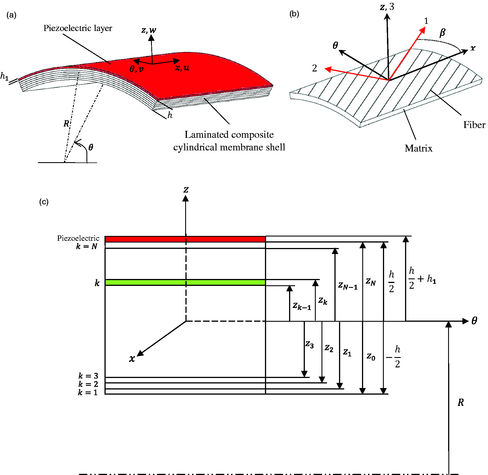
Layout of a laminated fiber-reinforced composite cylindrical membrane shell coupled with a piezoelectric layer at the top surface, a single ply of fiber-reinforced unidirectional composite cylindrical membrane shell, and a cross-sectional view of a piezoelectric coupled laminated composite cylindrical membrane shell are shown in Figure 1. Axial, circumferential, and radial directions are shown, respectively, by , , and . Directions 1, 2, and 3 denote, respectively, the material principle axes along the fiber and in transverse directions of the fiber. represents the angle between -axis and 1-axis measured in positive counterclockwise direction. The plane is the reference plane or the midplane. stands for the reference plane radius of the shell, denotes the total thickness of the laminated composite cylindrical shell which is sum of the thickness of each lamina (ply), and is the thickness of the piezoelectric layer.39,40 In this section, wave propagation problem in a piezoelectric coupled laminated fiber-reinforced composite cylindrical shell is modeled and solved based on the membrane shell theory.
(a) Layout of a laminated fiber-reinforced composite cylindrical membrane shell coupled with a piezoelectric layer, (b) a single ply of fiber-reinforced unidirectional composite cylindrical shell and its material principle and cylindrical coordinate system, and (c) a cross-sectional view of a piezoelectric coupled laminated composite cylindrical membrane shell with coordinate notation of individual plies.39,40
Constitutive equations for a laminated fiber-reinforced composite cylindrical membrane shell
Based on the membrane shell model, the transverse or out-of-plane shear forces, bending and twisting moments are assumed to be negligibly small. The displacement kinematics in the membrane shell model are41
where , , and are the displacements of a generic point in , , and directions, respectively; and , , and are the reference plane displacements in , , and directions, respectively. , , and are not function of for thin shell structures, hence, their derivatives with respect to will be zero in further computations in this study.
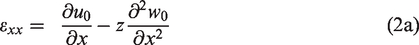
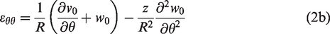
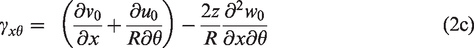
The general strain–displacement relations in cylindrical coordinate system , in view of equation (1), are given by
By defining
as the strain components on the reference plane, and the curvatures of the laminated composite shell as
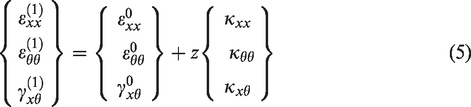
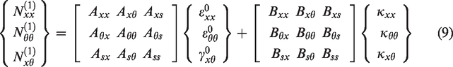
the in-plane strains at any point in the laminated composite shell can be expressed in terms of the reference plane strains and the laminate curvatures as follows
where is the distance of any point from the reference plane, and superscript (1) denotes variables corresponding to the host laminated composite shell.
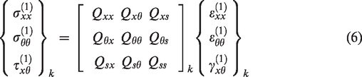
The in-plane stress–strain relations in the laminate coordinate system for an individual lamina (layer) whose midplane is at a distance from the reference plane are given by1
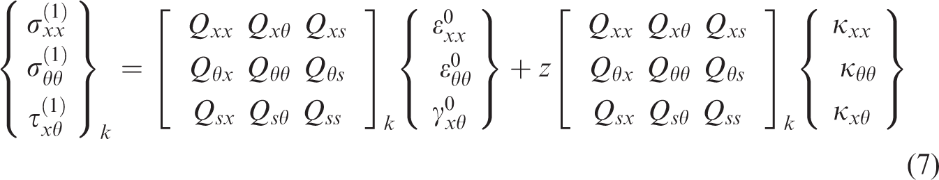
where is the transformed reduced stiffness matrix for each lamina in direction as a function of the principal stiffness matrix of the lamina reinforced with fibers, where their components are given in Appendix 1. The subscript in the above equations corresponds to shear stress and strain components referred to the system of coordinates. Substituting equation (5) into equation (6) gives
as the in-plane stress–strain relations for an individual lamina whose midplane is at a distance from the reference plane.
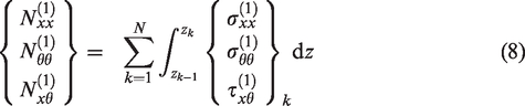
Since the piezoelectric layer is thin in compared with the host substrate laminated composite shell, the midplane of laminated composite shell is still considered as the neutral plane where there is no in-plane deformation during bending. Therefore, the resultant membrane forces in the host laminated composite shell are obtained by integrating the stresses across the thickness of the shell,1 as follows
where is the total number of composite layers and and are the -coordinate of the lower and upper surfaces of layer , respectively. Substituting equation (7) for the layer stresses into equation (8) and integrating across the shell thickness yields
where
where and , . and are laminate stiffness matrices which are functions of the geometry, material properties, and stacking sequence of the individual plies.
Constitutive equations for a piezoelectric layer
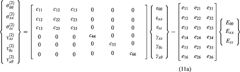
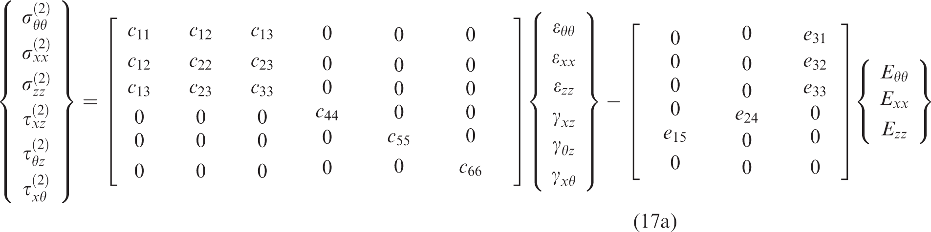
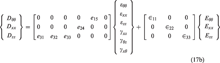
The generalized constitutive equations for a piezoelectric layer in the cylindrical coordinate system () are given by42
where , , and , denote the stresses, the strains, the electric displacements, and the electric field intensities, respectively; , represent the elastic constants, the piezoelectric constants, and the dielectric constants, respectively. Superscript (2) stands for variables corresponding to the piezoelectric layer. It is noted that regardless of the direction of polarization, there should be only five nonzero piezoelectric constants. The electric field intensities in the cylindrical coordinate system, which are function of the electric potential , are given by
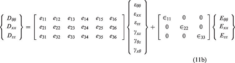
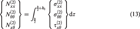
The resultant membrane forces for a piezoelectric layer bonded to the top surface of a laminated composite shell are also obtained by integrating the corresponding stresses across the thickness of the piezoelectric layer,18 i.e.
The constitutive relations for a piezoelectric shell layer with axial and radial polarizations based on the membrane shell model are obtained in the following.
Axial polarization
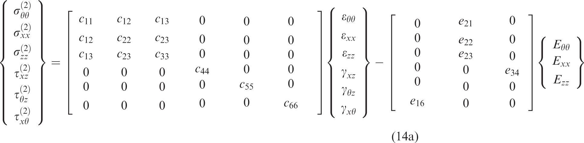
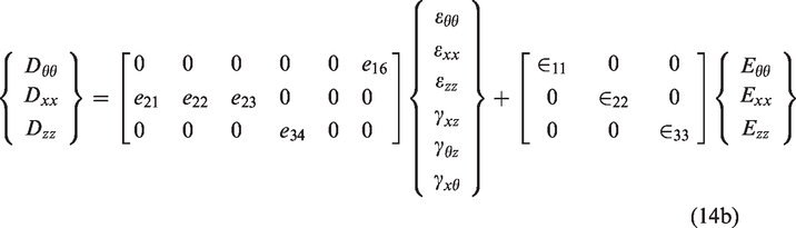
There are only five piezoelectric constants , , , , and for axial polarization of the piezoelectricity. Hence, the constitutive relations for a piezoelectric layer with axial polarization in the cylindrical coordinate system () are reduced to
Based on the membrane shell model, the normal stress in the shell thickness direction, , and the transverse shear stresses, and , are assumed negligible. Thus, based on this theory, from , , and in equation (14a), we obtain
Substituting equation (15) into equation (14) yields
where , , , , , , , and , , for axial polarization are given in Appendix 2, and the electric potential is also not a function of for axial polarization, , thus, its derivatives with respect to will be zero in further computations in this study.
Substituting the strain–displacement relations, equation (2), and the electric field intensities, equation (12), into equation (16) gives the stress–strain relations and the electric displacements for a piezoelectric layer with axial polarization in terms of , , , and . The resultant membrane forces (, and ) are obtained by substituting the corresponding stresses, equation (16a), into equation (13) and taking integration across the piezoelectric layer thickness.
Radial polarization
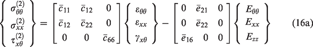
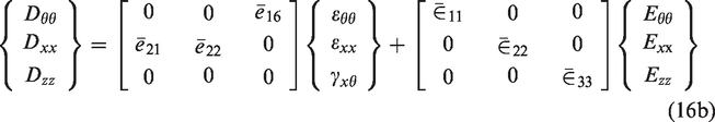
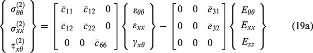
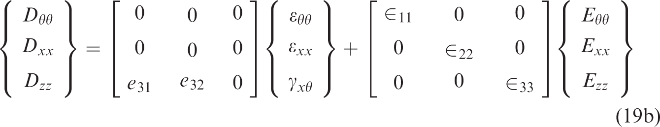
The five piezoelectric constants for radial polarization of the piezoelectricity are , , , , and . So, equation (11) for radial polarization is reduced to
By considering , , and in equation (17a) for a membrane shell model, we obtain
Substituting equation (18) into equation (17) yields
where , , , , , , and , , for radial polarization are given in Appendix 2.
For radial polarization of piezoelectricity, a closed (short)-circuit electrical boundary condition is considered. When electrodes at two surfaces of the piezoelectric layer are shortly connected, the electrical potential () is zero throughout the surface. Thus, for the closed (short)-circuit electrical boundary condition of a piezoelectric layer (with thickness ) attached to the top surface of a shell (with thickness ), we have
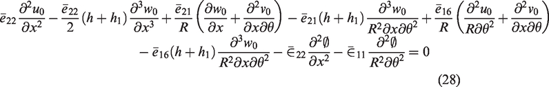
An electric potential solution for the piezoelectric layer needs to be established to strictly satisfy the closed-circuit electrical boundary condition. Different electrical potential solutions can be assumed to satisfy the closed-circuit electrical boundary condition. In this study, a cosine distribution of the electric potential () in the radial (thickness) direction of the piezoelectric layer is assumed as
where it satisfies the closed-circuit electrical boundary condition, equation (20). Hence, based on this cosine distribution of the electric potential (), the electric field intensities, equation (12), for radial polarization with closed-circuit boundary condition are obtained as
By substituting, the strain–displacement relations, equation (2), and the electric field intensities, equation (22), into equation (19), the stress–strain relations and the electric displacements for a piezoelectric layer with radial polarization and closed-circuit electrical boundary condition are obtained in terms of , , and . The resultant membrane forces (, and ) for radial polarization of the piezoelectricity are obtained by substituting the corresponding stresses, equation (19a), into equation (13) and taking integration across the piezoelectric layer thickness.
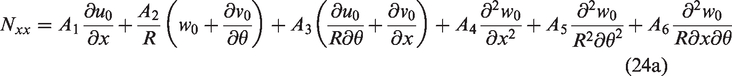
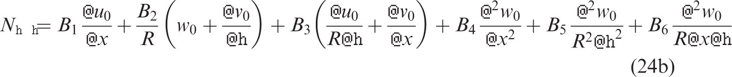
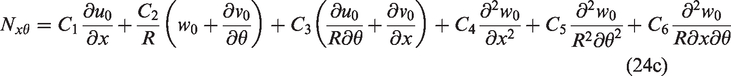
Force resultants for a piezoelectric coupled laminated composite cylindrical membrane shell
The resultant membrane forces in a piezoelectric coupled laminated fiber-reinforced composite cylindrical membrane shell are sum of the forces of the host laminated composite shell, equation (9), and the piezoelectric layer ones, equation (13). In the case of axial polarization, the resultant membrane forces are obtained as
and for radial polarization with closed-circuit electrical boundary condition and cosine distribution of the electrical potential (), the resultant membrane forces are obtained as
The expression of coefficients, and is given in Appendix 3.
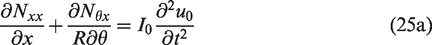
Equilibrium equations of motion
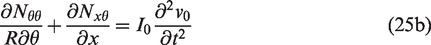
The equilibrium equations of motion for a membrane shell structure in the longitudinal (), tangential (), and radial () directions are, respectively43
where is the mass inertia for a piezoelectric coupled laminated composite shell which is given by
where and are mass densities of each lamina (layer) and piezoelectric layer, respectively.
Substituting equations (23) and (24) into equation (25) gives the equilibrium equations of motion, respectively, for axial and radial polarizations of piezoelectricity in terms of , , and .
The piezoelectric coupling effects are applied by considering the electric displacements in the corresponding Maxwell equation. By substituting the strain–displacement relations, equation (2), and the electric field intensities, equation (12), into equation (16b), the electric displacements for a piezoelectric layer with axial polarization are obtained as
Satisfying the Maxwell equation , in view of equation (27), yields
Equation (25), in view of equation (23), and equation (28) are the equilibrium equations of motion for a piezoelectric coupled laminated fiber-reinforced composite cylindrical membrane shell with axial polarization.
By substituting the strain–displacement relations, equation (2), and the electric field intensities, equation (22), into equation (19b), the electric displacements for a piezoelectric layer with radial polarization and cosine distribution of the electric potential for the closed-circuit electrical boundary condition are obtained as
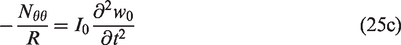
Satisfying the Maxwell equation , in view of equation (29), yields
Equation (25), in view of equation (24), and equation (30) give the equilibrium equations of motion for a piezoelectric coupled laminated fiber-reinforced composite cylindrical membrane shell with radial polarization and cosine distribution of the electric potential for closed-circuit electrical boundary condition.
Solution procedure
The displacements and electric potentials for wave propagation are assumed to be in the following forms
where , , and are axial wave number, circumferential wave number, and wave phase velocity, respectively; , , , and are the wave amplitudes; and is the corresponding frequency.
Substituting equation (31) into the equilibrium equations of motion yields a set of homogenous equations, respectively, for axial and radial polarizations of the piezoelectricity, i.e.
where the components of characteristics matrices and are given in Appendices 4 and 5, respectively. Due to the eigen value problem, the above matrix equations have a nontrivial solution for , , , and only if the determinant of matrices and equals zero. By solving equation (32), three positive roots are obtained for any specific axial wave number and circumferential wave number which are the wave phase velocities corresponding to the first three wave modes , , and .
By using a graphical numerical method, the wave phase velocities at any specific axial wave number and circumferential number can be searched by finding the eigen vectors of equation (32). Using this method leads to obtain the dispersion curves for different wave modes.
Numerical results and discussion
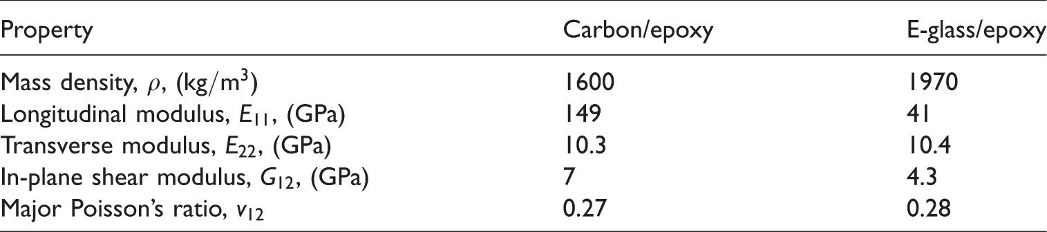
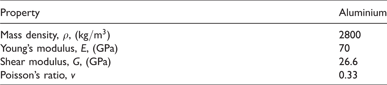
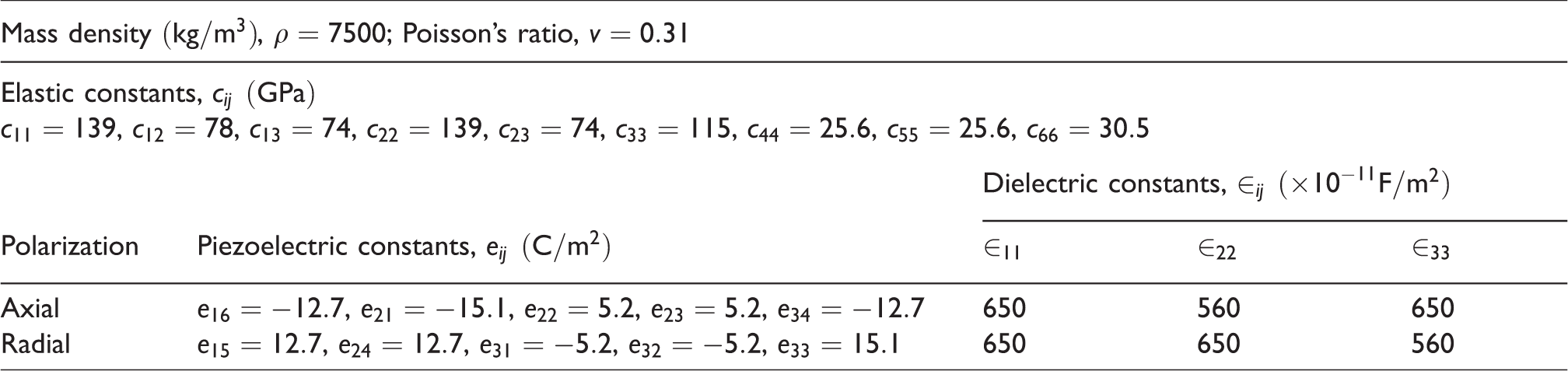
In this study, carbon/epoxy and E-glass/epoxy unidirectional composites and aluminium are considered for the host laminated shell where their material properties are given in Tables 1 and 2, and for the piezoelectric layer, PZT-4 is chosen where its material properties are listed in Table 3. To investigate wave propagation in a laminated fiber-reinforced composite cylindrical membrane shell coupled with a piezoelectric layer, the nondimensional wave phase velocity is employed in the numerical analysis. The axial wave number is defined by39
where is the axial wave number with unit and is the wavelength with unit meter (). By multiplying the axial wave number with , we obtain the nondimensional axial wave number as39
where is the total thickness of the piezoelectric coupled laminated composite shell. For any specific nondimensional axial wave number , its corresponding axial wave number or wavelength is obtained from equation (34), and then by substituting the calculated axial wave number or wavelength and a specific value of () into equation (32), the corresponding wave phase velocity is calculated for different wave modes. The nondimensional wave phase velocity is employed as18,23,24
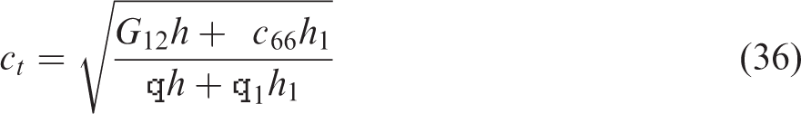
where is the phase velocity obtained from equation (32), and is the torsional wave velocity for a membrane shell model which is given by18
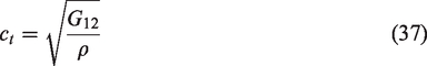
where is the in-plane shear modulus of a fiber-reinforced unidirectional composite given in Table 1 and is the effective in-plane shear modulus for a piezoelectric layer. In the case of no piezoelectric layer (), equation (36) is reduced to
Material properties for fiber-reinforced unidirectional composites.1
We define the ratio of piezoelectric layer thickness () to the host shell thickness () as .
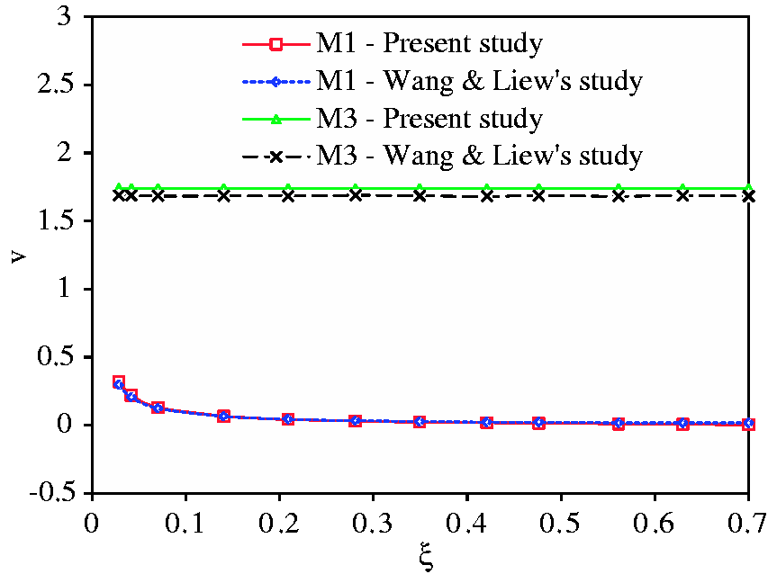
To validate the present methodology, the dispersion curves for wave modes 1 and 3 ( and ) are plotted in Figure 2 for a PZT-4 coupled aluminium cylindrical shell with axial polarization of the piezoelectric material, , and at the circumferential wave number and are compared with the results of Wang and Liew’s24 study. It is seen that there is a good agreement between the results of the present model and those of Wang and Liew’s24 study.
Comparison of dispersion curves of the present study with those of Wang and Liew’s24 study for a PZT-4 coupled aluminium cylindrical shell with axial polarization of the piezoelectric material, , and for wave modes 1 and 3 ( and M3) at .
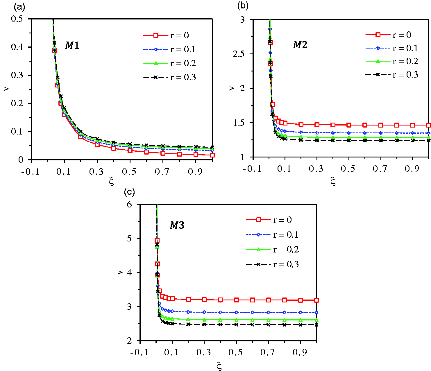
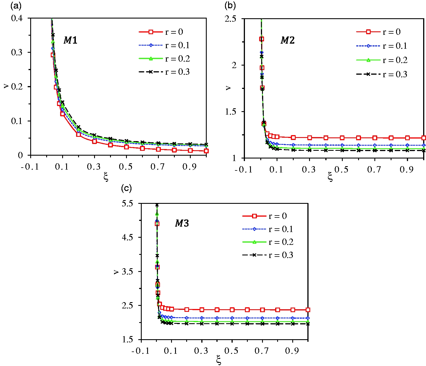
The dispersion curves for the first three wave modes ( and ) at for axial polarization of the piezoelectricity are displayed in Figures 3 and 4 for the pure host substrate shell () and the piezoelectric coupled shell with and when . For the host substrate shell, laminated carbon/epoxy composite (Figure 3) and laminated E-glass/epoxy composite (Figure 4) with stacking sequence are considered. Figures 3 and 4 illustrate the effects of piezoelectric layer on the wave phase velocities of the laminated carbon/epoxy composite and laminated E-glass/epoxy composite shells by changing its thickness. Within small range of the nondimensional axial wave numbers, (, the phase velocity decreases dramatically at first, and then changes smoothly with higher nondimensional axial wave numbers. For both carbon/epoxy and E-glass/epoxy composite host shells, at the first wave mode (), the phase velocity is higher with higher piezoelectric thickness ratio , while at the second and the third wave modes ( and ), the velocity decreases with the increase in the piezoelectric thickness (see Figures 3 and 4). It can also be seen that the phase velocities for the carbon/epoxy made host shell are higher than those of the E-glass/epoxy made one. Therefore, it is concluded that the effect of the piezoelectricity on the wave propagation behaviors is observable especially at higher wave modes.
Dispersion curves for a laminated carbon/epoxy composite cylindrical shell coupled with the piezoelectric layer with axial polarization for different piezoelectric thickness ratios () and the first three wave modes (, and ) at when .
Dispersion curves for a laminated E-glass/epoxy composite cylindrical shell coupled with the piezoelectric layer with axial polarization for different piezoelectric thickness ratios () and the first three wave modes (, and ) at when .
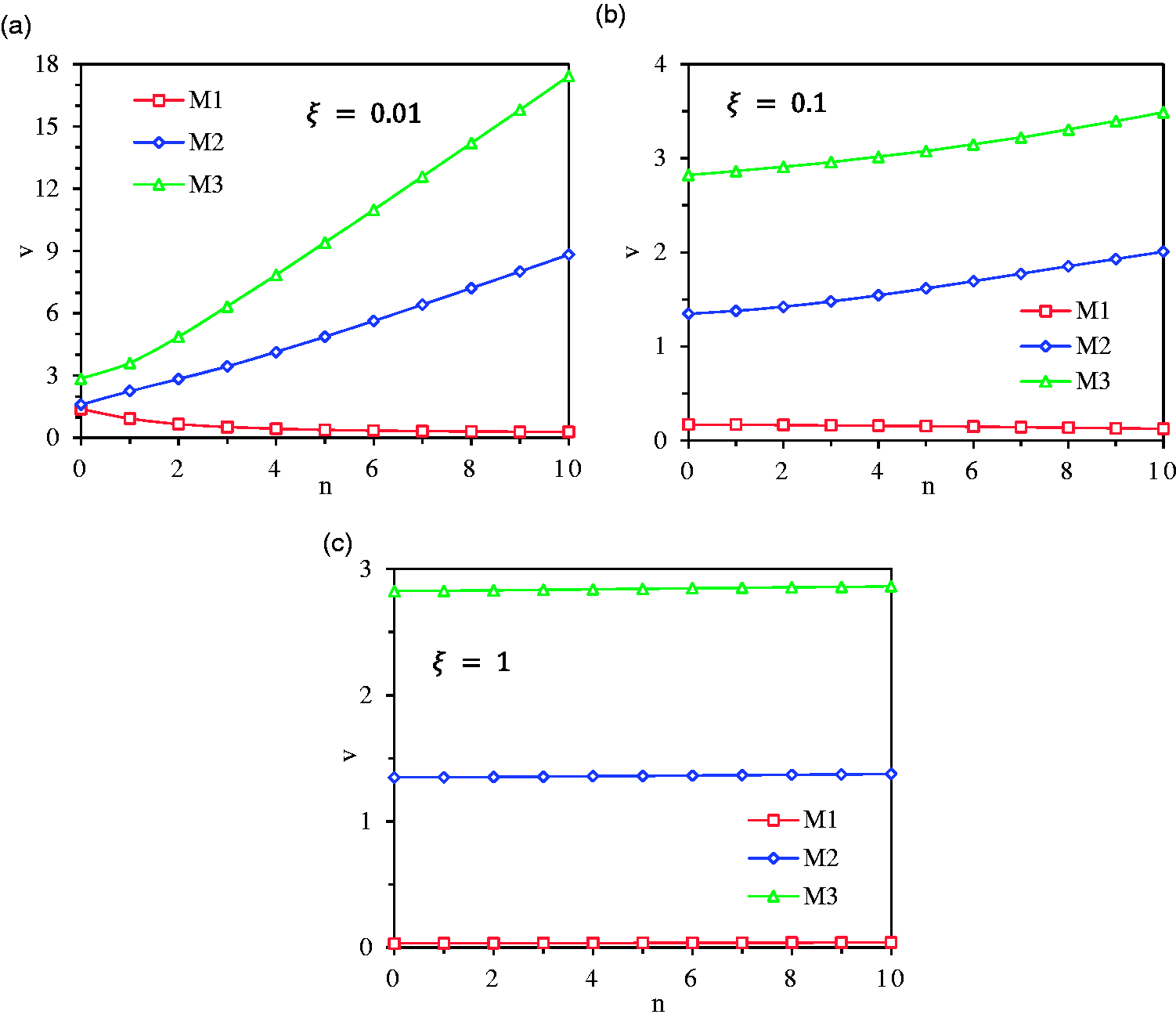
Figure 5 illustrates the effect of circumferential wave number () on the wave phase velocity (v) for the first three wave modes ( and ) for a laminated carbon/epoxy composite shell coupled with the piezoelectric layer with axial polarization, .1, and at , , and . At small nondimensional axial wave number , the wave phase velocity for the first wave mode () decreases slightly within lower circumferential wave numbers (), and within higher () it changes smoothly; while for wave modes 2 and 3 ( and ), the wave phase velocity increases sharply with the increment of . At nondimensional axial wave number , there is almost no variation of the phase velocity for the first wave mode () with the increase of the circumferential wave number (), while for wave modes 2 and 3 ( and ), the phase velocity increases slightly with the increase of . At higher nondimensional axial wave number , for all three wave modes, the phase velocity varies smoothly with the increase of the circumferential wave number . This phenomenon indicates that at lower axial wave numbers, there is a noticeable variation of the phase velocity with the circumferential wave number () especially at higher wave modes, while at higher axial wave numbers, the variation of the phase velocity with is approximately negligible, and the wave motion is independent of the circumferential wave number () which indicates axisymmetric wave motion can be considered at higher axial wave numbers.
Effect of circumferential wave number () on the nondimensional wave phase velocity (v) for the first three wave modes (, and ) of a laminated carbon/epoxy composite cylindrical shell coupled with the piezoelectric layer with axial polarization, .1, and at (a) , (b) , and (c) .
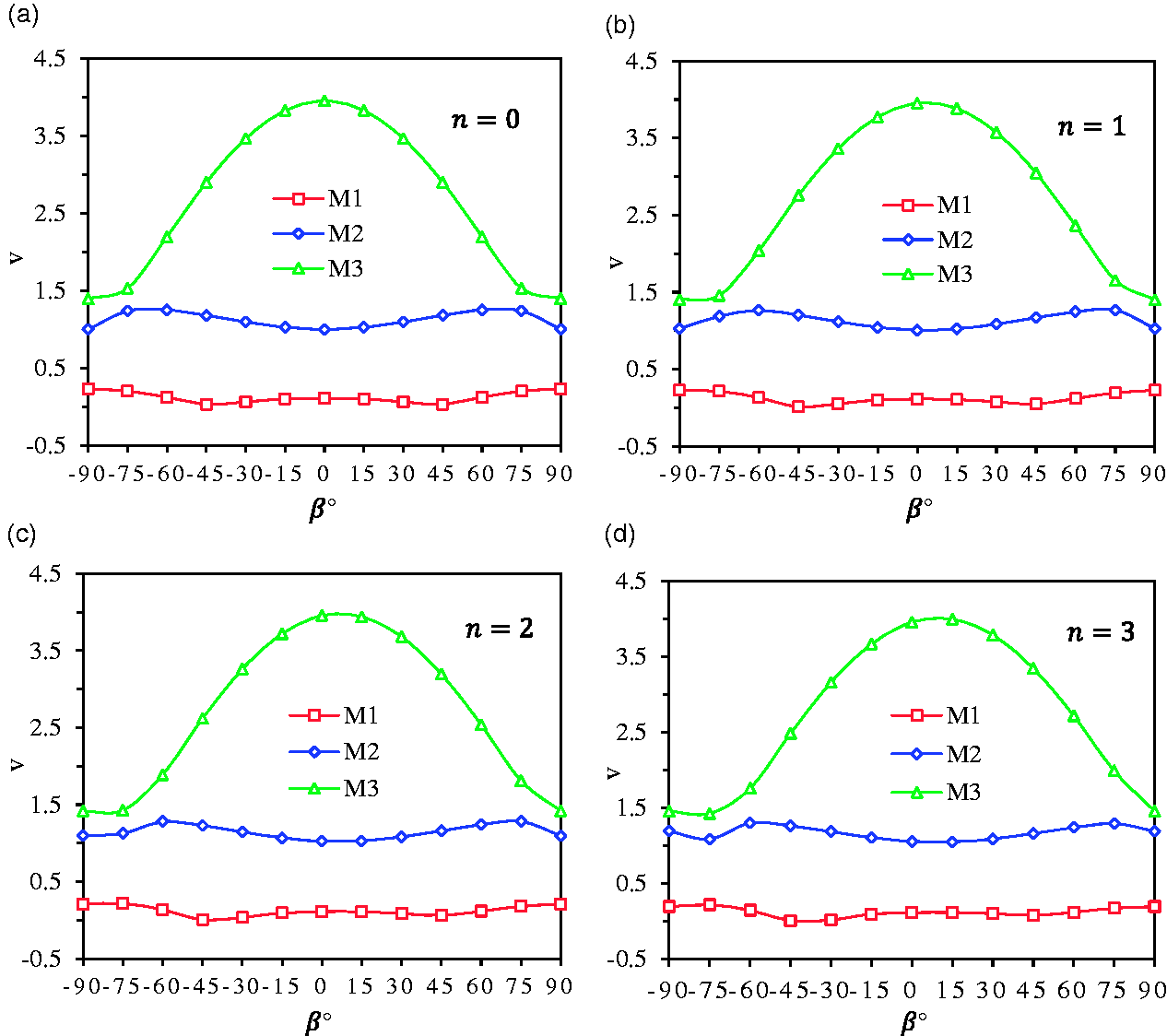
The variation of the wave phase velocity (v) with fiber orientations () for a single layer of carbon/epoxy composite shell coupled with the piezoelectric layer with axial polarization and is displayed in Figure 6 for the first three wave modes ( and ) at and and when . It is seen that for all three wave modes at , the phase velocities for fiber orientation are the same as those for fiber orientation, indicating the phase velocity curves are symmetric in respect to orientation (see Figure 6(a)). While, at and , the phase velocity curves for all three wave modes are not symmetric in respect to orientation and the phase velocities for orientation differ from those for orientation, but for and orientations, the phase velocities are still the same (see Figure 6(b) to (d)). Difference between the phase velocities of and orientations at is more significant than the difference at and , respectively. Effect of fibre orientation on the dispersion curves for the third wave mode () is more noticeable. Thus, it can be concluded that at higher , difference between the phase velocities of and fiber orientations will be more significant. However, the phase velocities for and fibre orientations are still the same even at higher circumferential wavenumbers ().
Effect of fiber orientation () on the nondimensional wave phase velocity for the first three wave modes (, and ) of a single layer of carbon/epoxy composite cylindrical shell coupled with the piezoelectric layer with axial polarization, , and at , and (a) , (b) , (c) , and (d) .
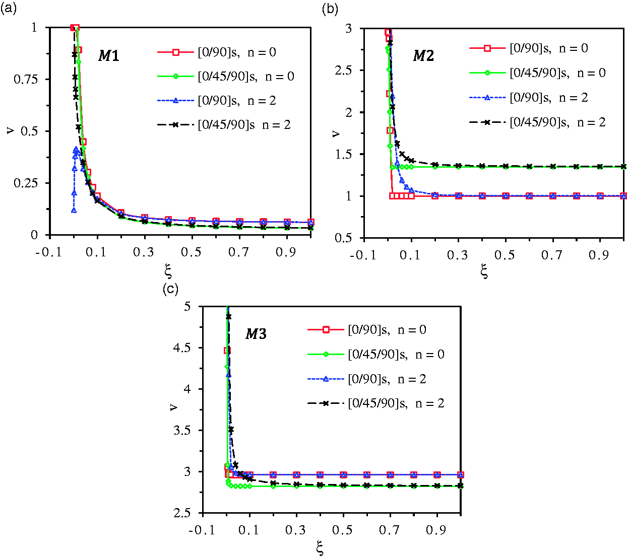
The effect of stacking sequence of the host substrate laminated fiber-reinforced composite shell on the dispersion curve is illustrated in Figure 7. Carbon/epoxy composite shells with symmetric and stacking sequences are considered. The phase velocities for the first three wave modes ( and ) at and are obtained for these two stacking sequences of the carbon/epoxy composite shell coupled with the piezoelectric layer with axial polarization, , and . It is observed that at the first and the third wave modes ( and ), the phase velocities for the cross-ply sequence are higher than those for the sequence (see Figure 7(a) and (c)), while at the second wave mode (), the phase velocities for the sequence are higher than those of the cross-ply sequence (see Figure 7(b)). Thus, it can be concluded that the stacking sequence of the host substrate composite shell has an obvious and significant effect on the wave propagation results.
Dispersion curves for and laminated carbon/epoxy composite cylindrical shells coupled with the piezoelectric layer with axial polarization, , and for the first three wave modes (, and ) at and .
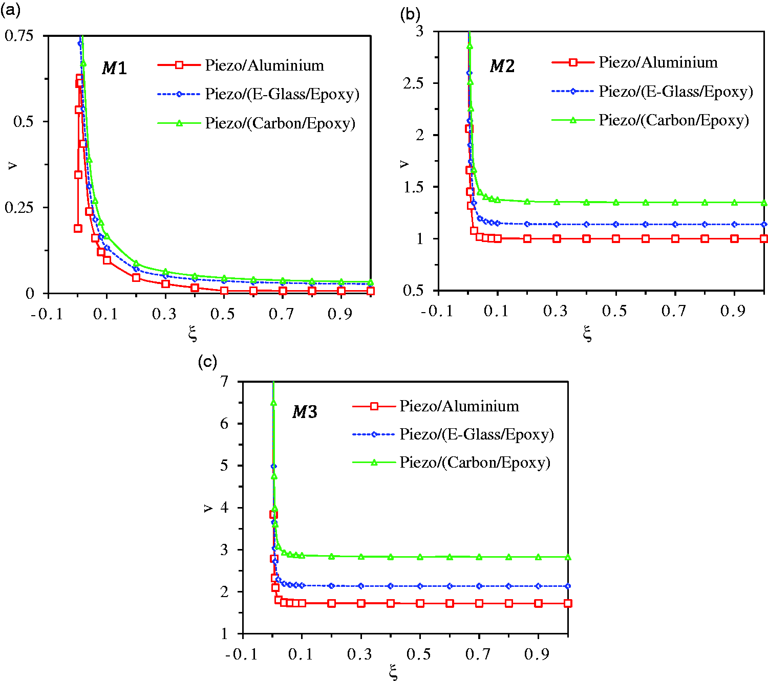
The effect of material properties of the host substrate shell on wave propagation behaviors is demonstrated in Figure 8. The phase velocity curves are plotted in Figure 8 for the first three wave modes ( and ) at for cylindrical shells with different core materials including aluminum, E-glass/epoxy composite, and carbon/epoxy composite. Shells are integrated with the piezoelectric layer with axial polarization, , and . It can be seen that for all three wave modes, the aluminum shell has the lowest phase velocities and the carbon/epoxy composite shell leads to the highest ones. This difference in the dispersion results is related to the difference in the material properties of these three core materials. Carbon/epoxy composite has higher elastic moduli and strength than E-glass/epoxy composite and aluminium leading to higher wave phase velocities.
Effect of material properties of the host substrate shell on the dispersion curves for a laminated composite cylindrical shell coupled with the piezoelectric layer with axial polarization, , and for the first three wave modes (, and ) at .
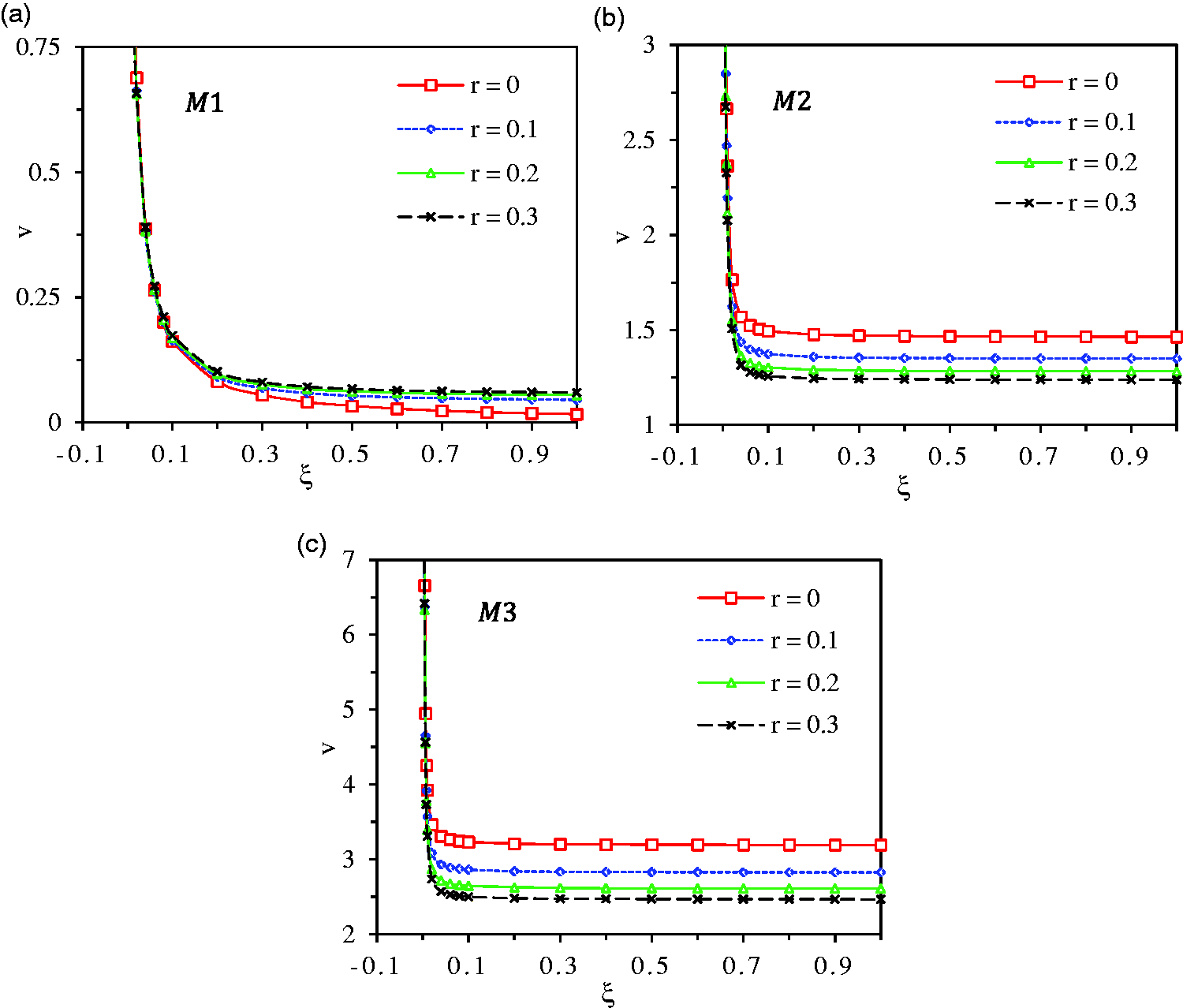
Figure 9 shows dispersion curves for a laminated carbon/epoxy composite cylindrical shell coupled with the piezoelectric layer with radial polarization and the closed-circuit electrical boundary condition on electrodes for different piezoelectric thickness ratios () and the first three wave modes (, and ) at when . A cosine distribution of the electric potential () satisfying the closed-circuit boundary condition is considered. It is seen that trend of dispersion curves for radial polarization of the piezoelectricity is the same as that for axial polarization shown in Figure 3. For the first wave mode (), the increase of the piezoelectric layer thickness leads to the increase of the phase velocities, and at wave modes 2 and 3 ( and ), it causes the decrease of the phase velocities.
Dispersion curves for a laminated carbon/epoxy composite cylindrical shell coupled with the piezoelectric layer with radial polarization and closed-circuit electrical boundary condition on electrodes for different piezoelectric thickness ratios () and the first three wave modes (, and ) at when .
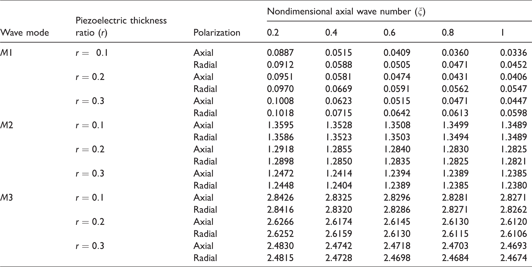
A comparison has been done on the effects of polarization direction of the piezoelectricity on the wave phase velocities at the first three wave modes (, and ) for a laminated carbon/epoxy composite cylindrical shell coupled with the piezoelectric layer for different piezoelectric thickness ratios () at when . Axial polarization and radial polarization with the closed-circuit electrical boundary condition and cosine distribution of the electric potential () are considered for the piezoelectric layer and the results are shown in Table 4. It is observed that at the first wave mode (), radial polarization leads to higher phase velocities than axial polarization; while at the second and the third wave modes ( and ), the phase velocities for axial polarization are higher than those for radial polarization. Therefore, it is concluded that difference between the wave propagation results for axial and radial polarizations is not much significant; however, it is dependent on the variation of the electric potential () considered for the electrical boundary conditions.
Comparison of the piezoelectricity axial polarization and radial polarization with closed-circuit electrical boundary condition on the variation of the nondimensional wave phase velocity (v) with the nondimensional axial wave number (ξ) for a laminated carbon/epoxy composite cylindrical shell coupled with piezoelectric layer for different piezoelectric thickness ratios () and the first three wave modes (, and ) at when .
Wave mode
Piezoelectric thickness ratio ()
Polarization
Nondimensional axial wave number (ξ)
0.2
0.4
0.6
0.8
1
Axial
0.0887
0.0515
0.0409
0.0360
0.0336
Radial
0.0912
0.0588
0.0505
0.0471
0.0452
Axial
0.0951
0.0581
0.0474
0.0431
0.0406
Radial
0.0970
0.0669
0.0591
0.0562
0.0547
Axial
0.1008
0.0623
0.0515
0.0471
0.0447
Radial
0.1018
0.0715
0.0642
0.0613
0.0598
Axial
1.3595
1.3528
1.3508
1.3499
1.3489
Radial
1.3586
1.3523
1.3503
1.3494
1.3489
Axial
1.2918
1.2855
1.2840
1.2830
1.2825
Radial
1.2898
1.2850
1.2835
1.2825
1.2821
Axial
1.2472
1.2414
1.2394
1.2389
1.2385
Radial
1.2448
1.2404
1.2389
1.2385
1.2380
Axial
2.8426
2.8325
2.8296
2.8281
2.8271
Radial
2.8416
2.8320
2.8286
2.8271
2.8262
Axial
2.6266
2.6174
2.6145
2.6130
2.6120
Radial
2.6252
2.6159
2.6130
2.6115
2.6106
Axial
2.4830
2.4742
2.4718
2.4703
2.4693
Radial
2.4815
2.4728
2.4698
2.4684
2.4674
Conclusions
In this study, wave propagation characteristics are investigated for smart laminated fiber-reinforced composite cylindrical membrane shells considering different piezoelectric coupling effects. Furthermore, the effects of stacking sequence, fiber orientation, and material properties of the host substrate shell on wave behaviors are investigated. General motion of wave propagation is utilized. Wave phase velocities for different wave modes at different axial and circumferential wave numbers are calculated by solving an eigenvalue problem. Effect of piezoelectric layer on the wave phase velocities is investigated by changing the piezoelectric layer thickness and considering axial polarization and radial polarization with closed-circuit electrical boundary condition. The dispersion curves for piezoelectric coupled laminated fiber-reinforced composite cylindrical shells made up of carbon/epoxy composite and E-glass/epoxy composite are plotted and compared with those of the piezoelectric coupled aluminum shell. Concluding remarks of this study are summarized as follows:
Lower axial wave numbers have noticeable effect on the wave phase velocities, while the variation of the phase velocities is negligible at higher axial wave numbers.
The effects of piezoelectricity on wave propagation characteristics are observable, where change of piezoelectric layer thickness and polarization direction lead to significant variations of wave velocities at different wave modes.
At lower axial wave numbers, the phase velocity varies significantly with the increase of the circumferential wave numbers, while this variation is negligible at higher axial wave numbers.
Fibre orientation and stacking sequence have obvious influences on wave propagation behaviors in piezoelectric coupled laminated fiber-reinforced composite cylindrical membrane shells. Effect of fibre orientation on the dispersion curves is more noticeable at higher wave modes. The stacking sequence influences significantly on the phase velocities.
Material properties of the host substrate shell have significant effect on wave propagation results.
The methodology presented in this study can be used as a fundamental model for future research on dynamics and wave propagation characteristics of smart laminated fiber-reinforced composite shells coupled with the piezoelectric layer for dynamic stability analysis and structural health monitoring applications. For future works, we will continue the study of different piezoelectric polarization directions, electrical boundary conditions, and charging distributions on piezoelectric layers and their effects on dynamics of smart composites.
Footnotes
Declaration of conflicting interests
The author(s) declared no potential conflicts of interest with respect to the research, authorship, and/or publication of this article.
Funding
The author(s) disclosed receipt of the following financial support for the research, authorship, and/or publication of this article: This research was undertaken, in part, thanks to funding supports from University of Manitoba, province of Manitoba, Research Manitoba with grant number SIMTReC Wu 2015-006 and Natural Sciences and Engineering Research Council of Canada (NSERC) with grant number 05013-15.
Appendix 1
References
1.
DanielIMIshaiO.Engineering mechanics of composite materials. 2nd ed.
New York:
Oxford University Press, 2006.
2.
LoveAEH.A treatise on the mathematical theory of elasticity.
New York:
Dover Publication.
3.
Donnell LH. Stability of Thin-Walled Tubes Under Torsion. NACA-TR-479, United States: California Institute of Technology, http://ntrs.nasa.gov/search.jsp?R=19930091553 (1 January 1935).
4.
Flügge W. Stresses in Shells. Berlin, Heidelberg: Springer, 1960.
5.
Vlasov VZ. General Theory of Shells and Its Application in Engineering. Washington: National Aeronautics and Space Administration, 1964.
6.
Sanders JL. An Improved First-approximation Theory for Thin Shells. Washington: U.S. Government Printing Office, 1960.
7.
KhdeirAAReddyJNFrederickD.A study of bending, vibration and buckling of cross-ply circular cylindrical shells with various shell theories. Int J Eng Sci1989;
27: 1337–1351.
8.
KhdeirAAReddyJNFrederickD.On the transient response of cross-ply laminated circular cylindrical shells. Int J Impact Eng1990;
9: 475–484.
ZhangXM.Vibration analysis of cross-ply laminated composite cylindrical shells using the wave propagation approach. Appl Acoust2001;
62: 1221–1228.
11.
ZhangXM.Parametric analysis of frequency of rotating laminated composite cylindrical shells with the wave propagation approach. Comput Methods Appl Mech Eng2002;
191: 2057–2071.
12.
SongMGeS.Dynamic response of composite shell under axial explosion impact load in tunnel. Thin-Walled Struct2013;
67: 49–62.
13.
CaoXHuaHWaX.Vibroacoustic comparisons of composite laminated cylindrical shells according to three shear deformation shell theories. Arch Appl Mech2014;
84: 1015–1036.
14.
SongXZhaiJChenYet al.
Traveling wave analysis of rotating cross-ply laminated cylindrical shells with arbitrary boundaries conditions via Rayleigh–Ritz method. Compos Struct2015;
133: 1101–1115.
15.
SongXHanQZhaiJ.Vibration analyses of symmetrically laminated composite cylindrical shells with arbitrary boundaries conditions via Rayleigh–Ritz method. Compos Struct2015;
134: 820–830.
16.
KhakimovaRCastroSGPWilckensDet al.
Buckling of axially compressed CFRP cylinders with and without additional lateral load: experimental and numerical investigation. Thin-Walled Struct2017;
119: 178–189.
17.
GaudenziP.Smart structures: physical behaviour, mathematical modelling and applications. Chippenham, Wiltshire:
John Wiley & Sons, 2009.
18.
WangQ.Wave propagation in a piezoelectric coupled cylindrical membrane shell. Int J Solids Struct2001;
38: 8207–8218.
19.
Bailey T and Hubbard JE. Distributed piezoelectric-polymer active vibration control of a cantilever beam. J Guid Control Dyn 1985; 8: 605–611.
CrawleyEFLuisJD.Use of piezoelectric actuators as elements of intelligent structures. AIAA J1987;
25: 1373–1385.
22.
WangB-TRogersCA.Laminate plate theory for spatially distributed induced strain actuators. J Compos Mater1991;
25: 433–452.
23.
WangQ.Axi-symmetric wave propagation in a cylinder coated with a piezoelectric layer. Int J Solids Struct2002;
39: 3023–3037.
24.
WangQLiewKM.Analysis of wave propagation in piezoelectric coupled cylinder affected by transverse shear and rotary inertia. Int J Solids Struct2003;
40: 6653–6667.
25.
DongKWangX.Wave propagation characteristics in piezoelectric cylindrical laminated shells under large deformation. Compos Struct2007;
77: 171–181.
26.
MindlinRD.Forced thickness-shear and flexural vibrations of piezoelectric crystal plates. J Appl Phys1952;
23: 83–88.
27.
TierstenHF.Wave propagation in an infinite piezoelectric plate. J Acoust Soc Am1963;
35: 234–239.
28.
BleusteinJL.Some simple modes of wave propagation in an infinite piezoelectric plate. J Acoust Soc Am1969;
45: 614–620.
29.
ElahiHEugeniMGaudenziPQayyum F, Swati RF and Khan HM.
Response of piezoelectric materials on thermomechanical shocking and electrical shocking for aerospace applications. Microsyst Technol2018;
24: 3791–3798.
30.
ElahiHEugeniMGaudenziPGul M, Swati RF. Piezoelectric thermo electromechanical energy harvester for reconnaissance satellite structure. Microsyst Technol. 2018. DOI: 10.1007/s00542-018-3994-z.
31.
ElahiHEugeniMGaudenziP.A review on mechanisms for piezoelectric-based energy harvesters. Energies2018;
11: 1850.
32.
BishehHWuN. Analysis of wave propagation characteristics in piezoelectric cylindrical composite shells reinforced with carbon nanotubes. Int J Mech Sci. 2018;145: 200–220.
33.
BishehHWuN.Wave propagation in piezoelectric cylindrical composite shells reinforced with angled and randomly oriented carbon nanotubes. Compos Part B Eng2019;
160: 10–30.
34.
KadoliRGanesanN.Studies on dynamic behavior of composite and isotropic cylindrical shells with PZT layers under axisymmetric temperature variation. J Sound Vib2004;
271: 103–130.
35.
DaiH-LZhengH-Y.Buckling and post-buckling analyses for an axially compressed laminated cylindrical shell of FGM with PFRC in thermal environments. Eur J Mech A Solids2011;
30: 913–923.
36.
GresilMGiurgiutiuV. Guided wave propagation in carbon composite laminate using piezoelectric wafer active sensors. Aeronaut J 2013; 117: 971–995.
37.
GresilMGiurgiutiuV.Prediction of attenuated guided waves propagation in carbon fiber composites using Rayleigh damping model. J Intell Mater Syst Struct2015;
26: 2151–2169.
38.
NasihatgozarMDaghighVEskandariMet al.
Buckling analysis of piezoelectric cylindrical composite panels reinforced with carbon nanotubes. Int J Mech Sci2016;
107: 69–79.
39.
BishehHWuN.Wave propagation characteristics in a piezoelectric coupled laminated composite cylindrical shell by considering transverse shear effects and rotary inertia. Compos Struct2018;
191: 123–144.
40.
BishehHWuN.Wave propagation in smart laminated composite cylindrical shells reinforced with carbon nanotubes in hygrothermal environments. Compos Part B Eng2019;
162: 219–241.
41.
Reddy JN. Mechanics of Laminated Composite Plates and Shells: Theory and Analysis. Second Edition. Boca Raton: CRC Press, 2003.
GraffKF.Wave motion in elastic solids.
New York:
Dover Publication.
44.
HasheminejadSMAlaei-VarnosfaderaniM.Acoustic radiation and active control from a smart functionally graded submerged hollow cylinder. J Vib Control2014;
20: 2202–2220.