
Abstract
Misalignment is a common fault occurring in the rotor system. However, the response characteristics have not been understood comprehensively, especially the relation between forces or torques and displacements, accelerations, or moments. First, misalignment modeling is investigated in this paper. Two coupled rotor system is modeled by six degrees of freedom. Misalignment effects are considered at coupling location using nodal force vectors and moment vectors. Second, Newmark-β method is used to solve the nonlinear equations. Acceleration, displacement, and force or moment response characteristics are discussed. Some results are obtained as follows: (1) 2× will appear in the parallel misalignment forces spectrum, and 0× will appear in the vertical force spectrum; 2×, 4×, 6× will appear in the angular misalignment moment spectrum. (2) In parallel misalignment simulation, it is found that multifrequency components are more obvious, static components are showed in vertical forces and displacements, 1× is dominated and 2× is weak in the displacement spectrum, and 2× is obvious in the force spectrum; acceleration is periodic impulse signal and 1× and 2× are dominated in its spectrum; vertical displacement is truncated and its values are positive, the orbit looks like an inverted triangle. (3) In angular misalignment simulation, it is found that multifrequency components of response are more obvious, 2× is obvious in the vertical displacement spectrum, and 2× is dominated in the moment spectrum; acceleration is periodic impulse signal, horizontal and vertical displacements are periodic, the orbit looks like a moon or an eight shape, and 2× is obvious in the moment spectrum.
Introduction
Misalignment is a common fault occurring in rotary machine, which is caused by unequal foundation movement or uneven thermal heating in rotor system. Misalignment can be divided into two types, one is the angular misalignment and the other one is the parallel misalignment. Misalignment cannot be reduced wholly. However, the relation between response and forces or moments has not been known comprehensively. Although many researchers acknowledge the adverse effect of misalignment on the dynamic performance of the rotor system, relative fewer studies have been conducted in this regard.
Experimental and theoretical works have been conducted by many researchers. Tejas et al. 1 used the experimental approach for the first time for the determination of magnitude and harmonic nature of the misalignment excitation. The force vector is used for the misalignment coupling stiffness matrix, derived from the experimental data and applied the misalignment coupling stiffness rotor. Alok et al. 2 used stator current signature to diagnose misalignment. It is found that misalignment is responsible for the cause of instability. Hariharan et al. 3 used experiments and ANSYS analysis to study the shaft misalignment. It is found that the misalignment effect can be amplified when the 2× running speed is close to the system natural frequency. Amit et al. 4 used Lagrangian approach to derive the misalignment equation. Newton–Raphson method is obtained from the dimensionless form. Discrete wavelet transform is used to analyze the signal. Wang et al. 5 studied the dual-rotor system with unbalance-misalignment coupling faults from simulation and experiments. Prabhakar et al. 6 analyzed the transient response of a misalignment rotor–coupling–bearing system passing through the critical speed. The continuous wavelet transform has been used to extract the silent features. Saavedra and Ramirez 7 deduced a new coupling finite element stiffness matrix and considered the frequency response functions from theory and experiments. Janusz 8 analyzed the character of the rotor’s longitudinal vibration with large misalignment. Guan et al. 9 proposed two kinds of dynamic models of shaft misalignment. Simulation and experiments have been done. Michael et al. 10 compared the spectral analysis, orbitals, and full spectrum. It is found that full spectra can distinguish imbalance from misalignment by looking at forward and reversed phenomena. Sekhar et al. 11 used higher order finite elements and developed the reaction forces and moments due to flexible coupling misalignment. Wan et al. 12 used a numerical integration method to analyze the nonlinear dynamic behaviors and stability of a multidisk rotor supported by oil-lubricated journal bearing with coupling misalignment. Li et al. 13 used simulations and experiments to research the dynamic behaviors and vibration mechanisms of multirotor bearing system with parallel and angular misalignments. Feng et al. 14 studied the bearing misalignment of an inner-and-outer dual-rotor system of an aero-engine with numerical calculation. Li et al. 15 established a dynamic model of the misalignment fault of a twin spool rotor with inter-shaft bearing. The vibration features of high- and low-pressure rotors were revealed by numerical analysis and experiment.
In previous research, many researchers have conducted some simulation and experiments on angular and parallel misalignments. However, the relation between forces or torques and response has not been investigated comprehensively. In order to better understand the misalignment faults, a rotor-coupling coupled model is established by six degrees of freedom, and angular and parallel misalignment model is used to simulate fault characteristics. The response characteristics are analyzed to reveal the mechanism of the effect of misalignments with respect to forces (torques) and response.
Misalignment modeling
A rotor model
Figure 1 shows the sketch of two rotors with three disks. Each rotor is supported by two bearings and two rotors are connected by coupling. Figure 2 is the finite element model (FEM) of the two rotor systems where the 6th and 12th nodes of rotor 1 is fixed on the ground, the 3rd and 7th nodes of rotor 2 is fixed on the ground, the first disk is at the 3rd node of rotor 1, the second disk is at the 15th node of rotor 1, and the third disk is at the 6th node of rotor 2. The bearing is simplified as string element. Without misalignments, the two rotor systems are linear systems; otherwise, the whole system with misalignment fault is a nonlinear system.
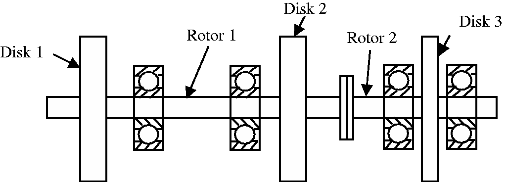
Sketch of two rotors connected by coupling.
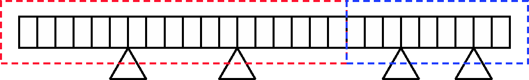
FEM of two rotor system.
The main parameters of rotor 1 are as follows: the diameter of the shaft is 30 mm; the length of the shaft is 880 mm, the mass of the two disks is mp1 = 10 kg and mp2 = 10 kg; the polar moment of inertia of the two disks is Jdp1 = 0.05 kg/m2 and Jdp2 = 0.05 kg/m2; and the equatorial moment of inertia of the two disks is Jdd1 = 0.025 kg/m2 and Jdp2 = 0.025 kg/m2, for E = 2.1 × 10¹¹ Pa, μ = 0.3, ρ = 7800 kg/m3.
The main parameters of rotor 2 are as follows: the diameter of the shaft is 40 mm; the length of the shaft is 40 mm, the mass of the disk is mp3 = 2 kg; the polar moment of inertia of the disk is Jdp1 = 0.05 kg/m2; and the equatorial moment of inertia of the disk is Jdd1 = 0.025 kg/m2, for E = 2.1 × 10¹¹ Pa, μ = 0.3, ρ = 7800 kg/m3.
The bearing line stiffness in x and y directions are 7.5 × 10⁶ N/m and 5 × 10⁷ N/m. The line damping is 2000 N·m/s. The bearing angular stiffness in x and y directions are 1 × 10³ N/m and 1 × 10³ N/m. The angular damping is 100 N·m/s.
Misalignment modeling
Parallel misalignment
Figure 3 shows the coordinate system for parallel misalignment of two rotors where two rotors are forced by
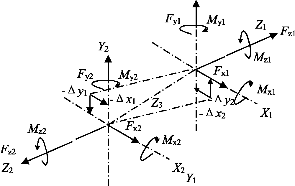
Coordinate system for parallel misalignment of two rotors.
Figures 4 and 5 show the mechanical and movement diagram of coupling misalignment fault. In Figure 4, O1 and O2 are the rotating center of left and right shaft, FR and FL are the forces of the left and right parts acting on the bolt, P is the bolt connector on the coupling, and θ is the angle of FR and y-axis. In Figure 5,
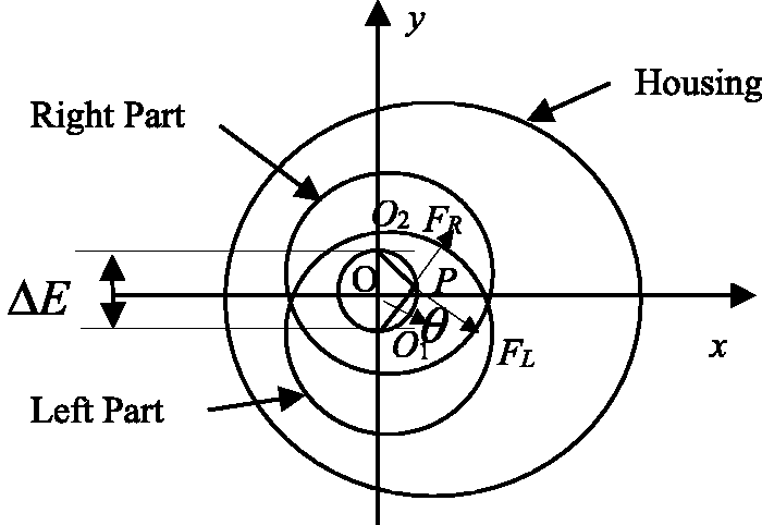
Mechanical diagram of parallel misalignment fault.
Movement diagram of parallel misalignment fault.
In Figure 5, when the coupling is rotating, the rotating radius R > r, so there is a tendency to pull two shafts together and two half couplings are deformed compressively. In Figure 5, O2B is perpendicular to O1P, as r ≫ ΔE, PB = r and O1B can be expressed as follows

If the size and material are the same for the two half couplings, their deformations are the same, which can be expressed as follows

Assuming that the stiffness of coupling bolt in O1P direction is kb, the force acting on two half couplings can be expressed as follows

The force is decomposed in x and y directions, which can be expressed as follows


These two forces acting on the left half coupling will act on the right half coupling, which can be expressed as follows

In equations (4) and (5), the forces are varying with 2×, i.e. the radius forces will change two times rotating speeds when the coupling rotates for a revolution.
Angular misalignment
Figure 6 shows the sketch of forces and moments for angular misalignment. There is a slight amount of angle misalignment α between two coupling shafts. It is assumed that the coordinate system X1Y1Z1 is established in rotor 1, and coordinate system X2Y2Z2 is established in rotor 2. The centerline of rotor 1 is axis Z1 and the centerline of rotor 2 is axis Z2 where two rotors are forced by
Coordinate system for angular misalignment of two rotors.
Figure 7 shows torque decomposition of angular misalignment in three directions. Torque T from rotor 1 is transmitted to rotor 2, which can be decomposed into two parts, and can be expressed as follows
Torque decomposition of angular misalignment.
Ts can be decomposed into two components in x and y directions, which can be expressed as follows
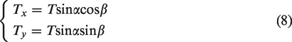
As rotor 2 rotates around axis Z2,
As for rotors with angle misalignment
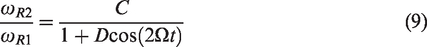
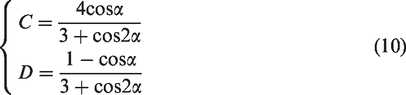
Equation (9) can be expanded as follows

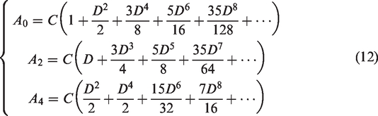
Equation (11) can be differentiated as follows

Equation (13) is substituted in equation (8), and input torque can be expressed as follows
Equation (14) is substituted in equation (7) and torques in x and y directions can be expressed as follows
In equation (15), the misalignment forces can be expressed as follows
Solving method
Newmark-β method is used to solve the differential equation of two rotor systems, and the movement equation can be illustrated as follows

In this paper,

Results and discussion
Characteristics analysis of parallel misalignment
In the simulation of parallel misalignment, misalignment amount ΔE is 1 × 10⁻³ m and stiffness kb is 1 × 10⁵ N/m. The acceleration, displacements, and forces of coupling of rotor 1 (node 1) are obtained.
Figure 8(a) to (e) shows the waterfall of acceleration, displacement, and forces. In Figure 8(a), 1×, 2× will appear in the acceleration waterfall when the rotating speeds are between 1000 r/min and 10,000 r/min; 4× will appear in the acceleration waterfall when the rotating speeds are between 5000 r/min and 10,000 r/min; 6×and 8× will appear when the rotating speeds are between 5000 r/min and 6000 r/min in the acceleration waterfall due to the resonance of rotor system.
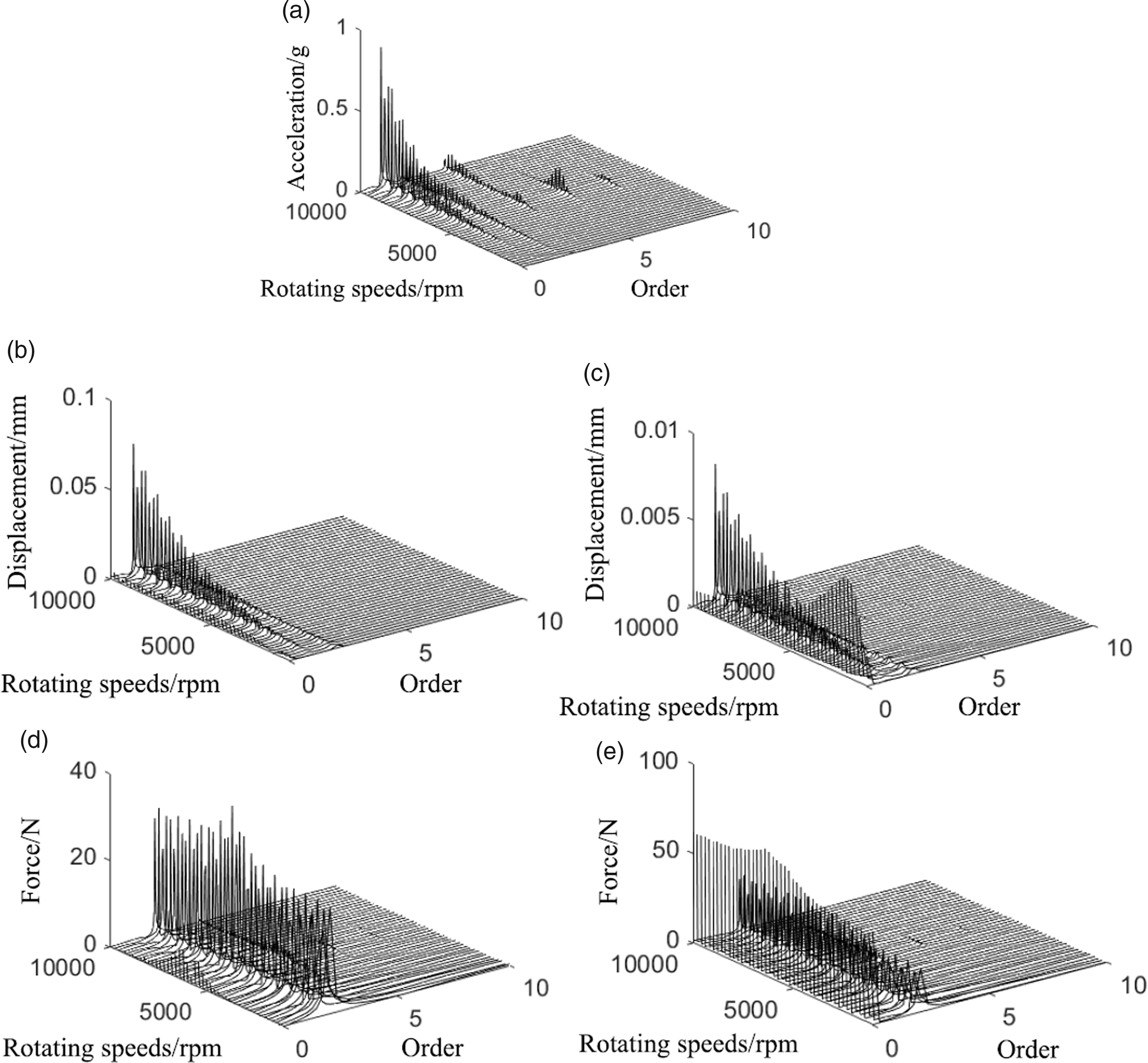
Waterfall of acceleration, displacements, and forces: (a) waterfall of acceleration; (b) waterfall of horizontal displacement; (c) waterfall of vertical displacement; (d) waterfall of horizontal force; (e) waterfall of vertical force; (d) waterfall of horizontal force; and (e) waterfall of vertical force.
In Figure 8(b) and (c), 1×, 2× will appear in the displacement waterfall when the rotating speeds are between 1000 r/min and 10,000 r/min. Meanwhile, 0× will appear in the vertical displacement waterfall. Also, when the rotating speed is at the first-order resonance speed 2400 r/min, 0× is dominant.
In Figure 8(d) and (e), 2× is dominant in the force waterfall when the rotating speeds are between 1000 r/min and 10,000 r/min. 4× and 6× will appear in the force waterfall when the rotating speeds are around the second-order resonance speed 6000 r/min. 0× will appear in the vertical force waterfall.
Figure 9(a) to (k) shows the acceleration, displacements, orbits, and force and response spectrums when the rotating speed is 3800 r/min. In Figure 9(a) and (b), acceleration is periodic impulse signal and 1× and 2× are dominated in its spectrum. In Figure 9(c) to (f), horizontal and vertical displacements are periodic signal. However, vertical displacement is truncated and its values are positive, which means its 0× is obvious in its spectrum. The orbit looks like an inverted triangle in Figure 9(g). In Figure 9(h) to (k), the horizontal and vertical force waves are periodic signals and 2× is obvious. However, the vertical force is positive and its 0× is obvious in its spectrum.
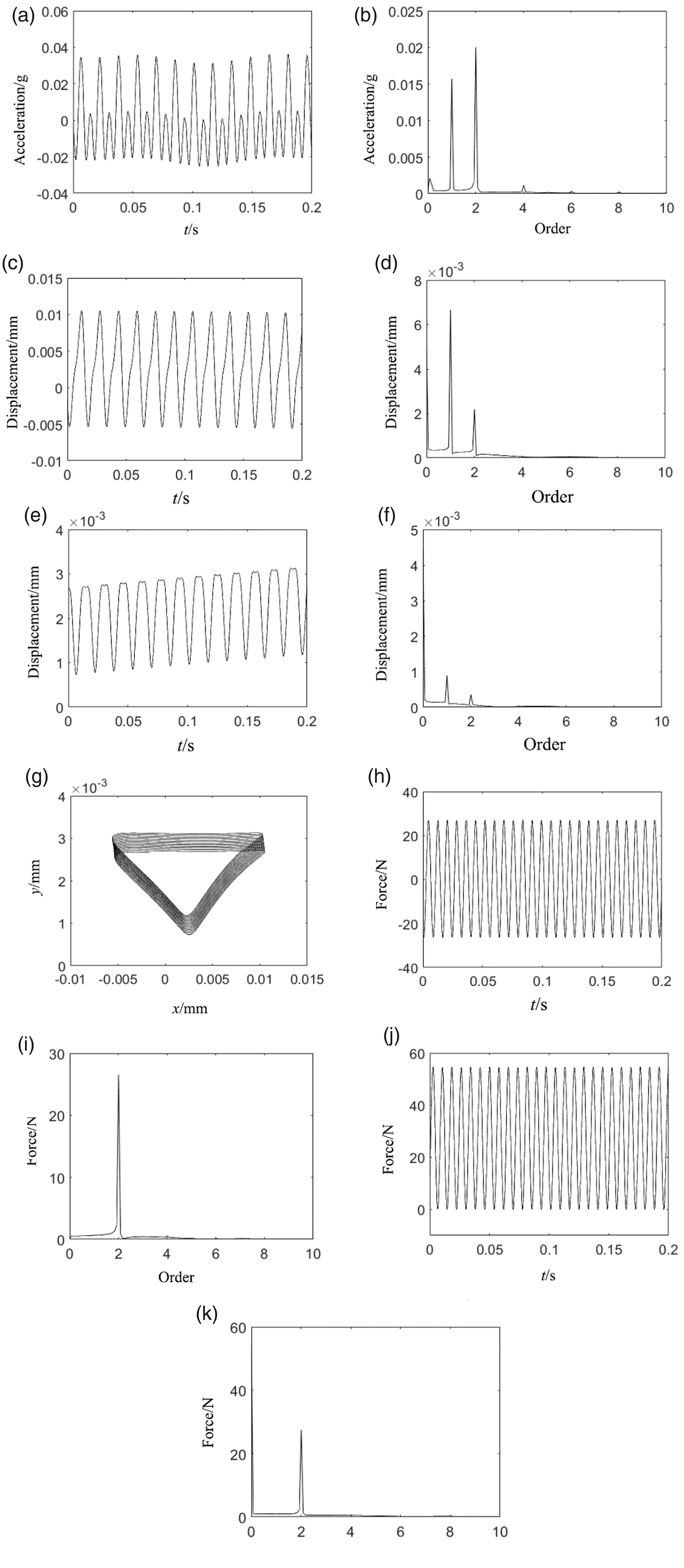
Acceleration, displacements, orbits, and forces and response spectrum when the rotating speed is 3800 r/min: (a) acceleration wave; (b) acceleration spectrum; (c) horizontal displacement wave; (d) horizontal displacement spectrum; (e) vertical displacement wave; (f) vertical displacement spectrum; (g) orbit; (h) horizontal force wave; (i) horizontal force spectrum; (j) vertical force wave; and (k) vertical force spectrum.
Figure 10(a) to (k) shows the acceleration, displacements, orbits, and force and response spectrums when the rotating speed is 5200 r/min. In Figure 10(a) and (b), acceleration is the periodic impulse signal and 1×, 2 × 4×, 6×, and 8× are dominated in its spectrum. In Figure 10(c) to (f), horizontal and vertical displacements are periodic signals. The orbit looks like an inverted triangle in Figure 10(g). In Figure 10(h) to (k), the horizontal and vertical force waves are periodic signals and 2× is obvious. However, the vertical force is positive and its 0× is obvious in its spectrum.
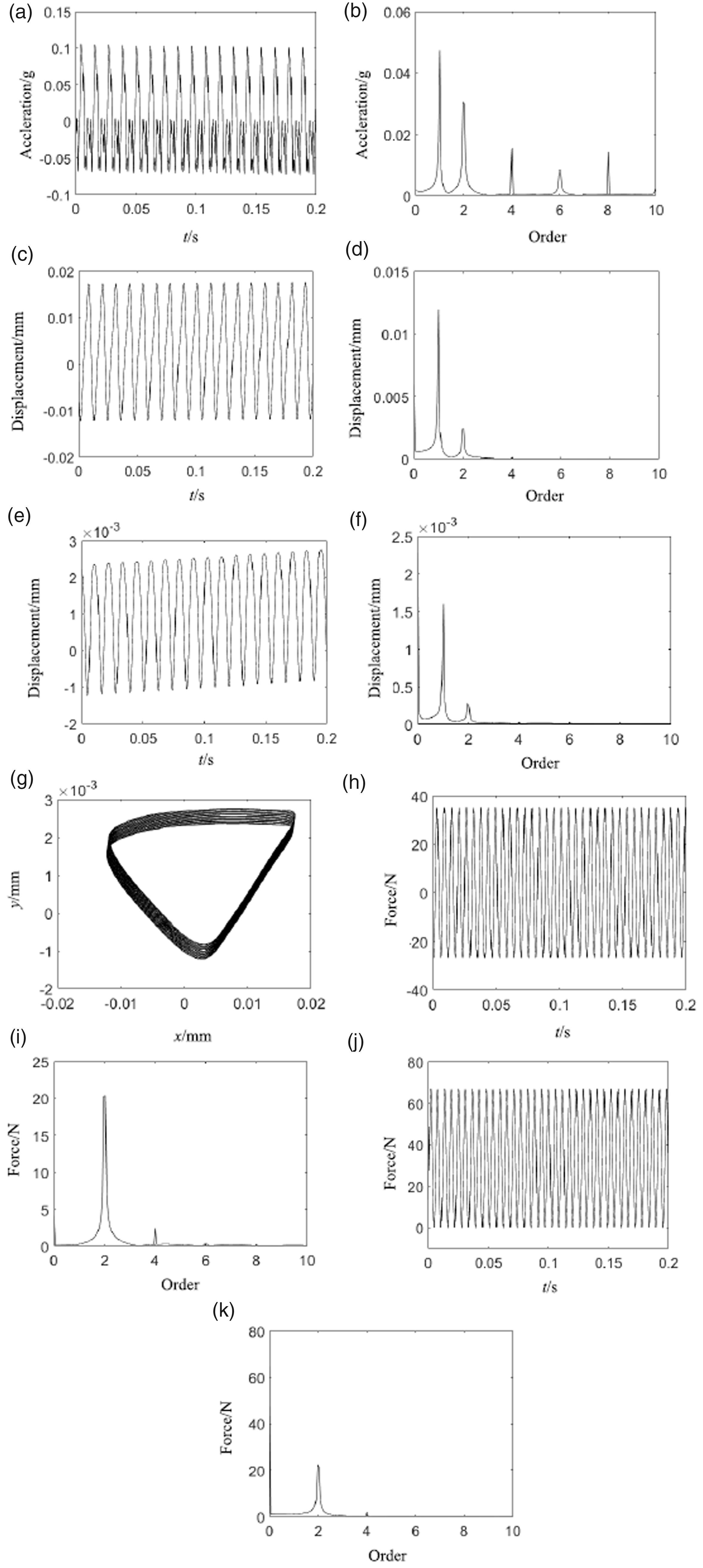
Acceleration, displacements, orbits, and force and response spectrum when the rotating speed is 5200 r/min: (a) acceleration wave; (b) acceleration spectrum; (c) horizontal displacement wave; (d) horizontal displacement spectrum; (e) vertical displacement wave; (f) vertical displacement spectrum; (g) orbit; (h) horizontal force wave; (i) horizontal force spectrum; (j) vertical force wave; and (k) vertical force spectrum.
Characteristics analysis of angular misalignment
In the simulation of angular misalignment, the angular misalignment amount is 5°, the polar initial moment JR is 5 × 10⁻³ kg/m2, and angle β is 30°. The acceleration, displacements, and moments of coupling of rotor 1 (node 1) are obtained.
Figure 11(a) to (e) shows waterfall of acceleration, displacement, and moments. In Figure 11(a), 1×, 2× will appear in the acceleration waterfall when the rotating speeds are between 5000 r/min and 10,000 r/min. In Figure 11(b) and (c), 1×, 2× will appear in the displacement waterfall when the rotating speeds are between 1000 r/min and 10,000 r/min. In Figure 11(d) and (e), 2× is dominant in the moment waterfall when the rotating speeds are between 1000 r/min and 10,000 r/min.
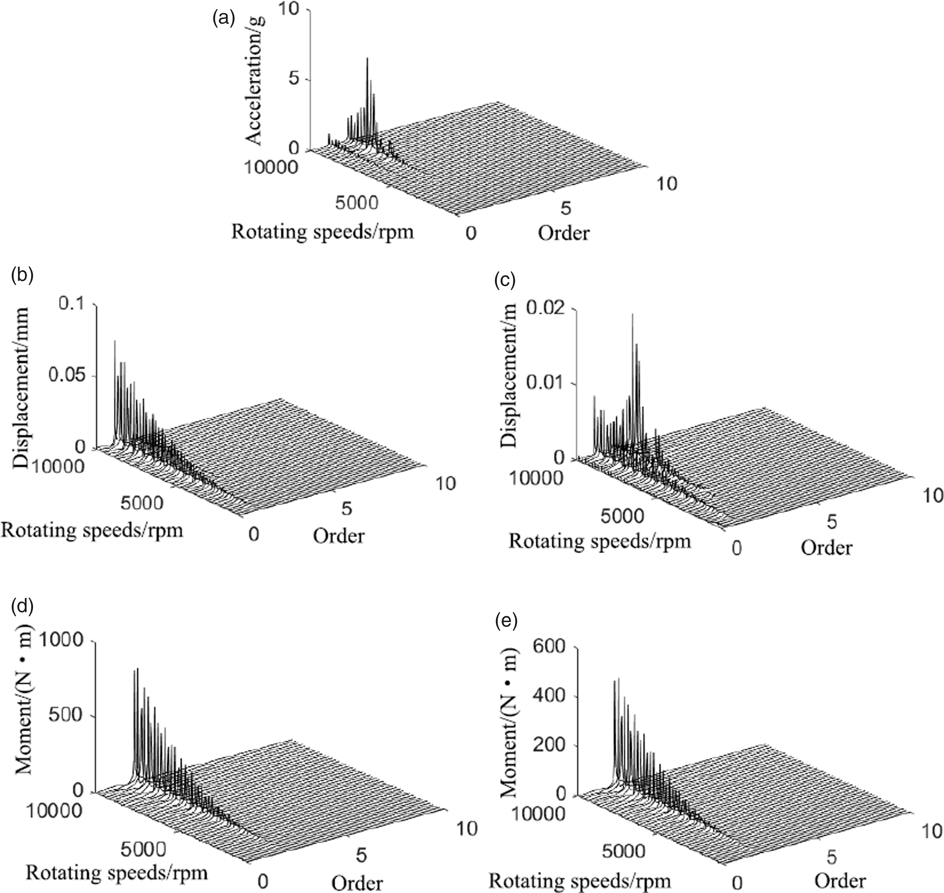
Waterfall of acceleration, displacements, and moments: (a) waterfall of acceleration; (b) waterfall of horizontal displacement; (c) waterfall of vertical displacement; (d) waterfall of horizontal moment; and (e) waterfall of vertical moment.
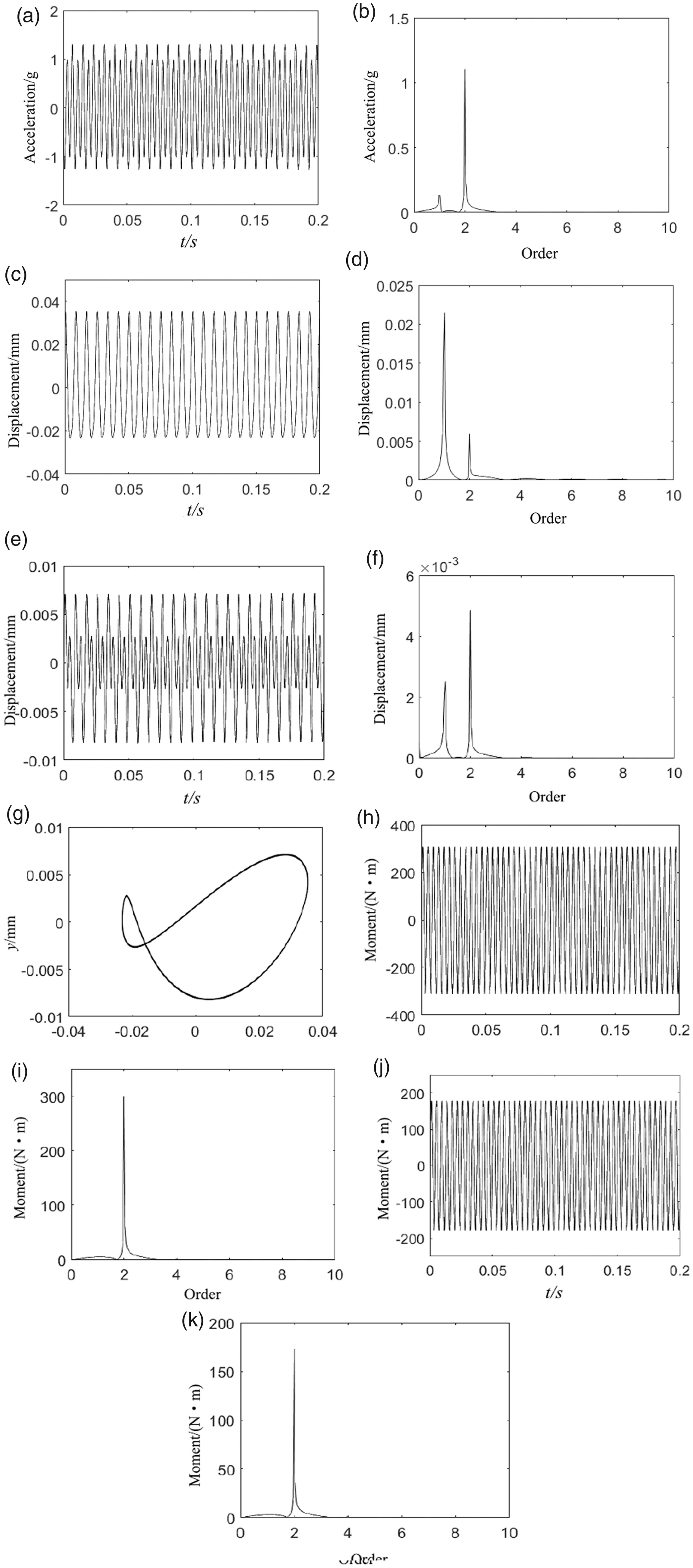
Figure 12(a) to (k) shows the acceleration, displacements, orbits, and moments and response spectrums when the rotating speed is 6400 r/min. In Figure 12(a) and (b), acceleration is periodic impulse signal and 1×, 2× are dominated in its spectrum. In Figure 12(c) to (f), horizontal and vertical displacements are periodic signals and 1×, 2× are dominated in their spectrums. The orbit looks like a moon in Figure 12(g). In Figure 12(h) to (k), the horizontal and vertical moment waves are periodic signals and 2× is obvious in their spectrums.
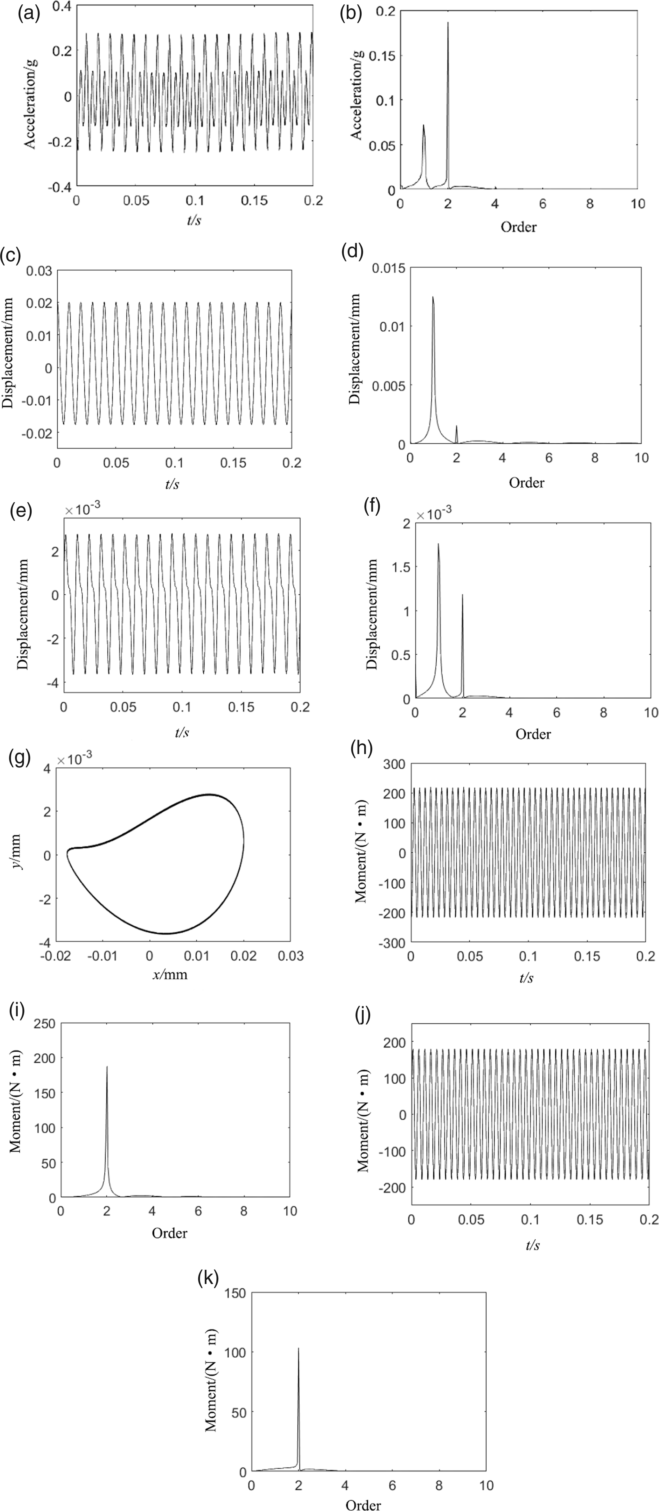
Acceleration, displacements, orbits, and force and response spectrum when the rotating speed is 6400 r/min: (a) acceleration wave; (b) acceleration spectrum; (c) horizontal displacement wave; (d) horizontal displacement spectrum; (e) vertical displacement wave; (f) vertical displacement spectrum; (g) orbit; (h) horizontal moment wave; (i) horizontal moment spectrum; (j) vertical moment wave; and (k) vertical moment spectrum.
Figure 13(a) to (k) shows the acceleration, displacements, orbits, and moments and response spectrum when the rotating speed is 7600 r/min. In Figure 13(a) and (b), acceleration is the periodic impulse signal and 1×, 2× are dominated in its spectrum. In Figure 13(c) to (f), horizontal and vertical displacements are periodic signals and 2× is dominated in their spectrums. The orbit looks like an eight shape in Figure 13(g). In Figure 13(h) to (k), the horizontal and vertical moment waves are periodic signals and 2× is obvious in their spectrums.
Acceleration, displacements, orbits, and force and response spectrum when the rotating speed is 7600 r/min: (a) acceleration wave; (b) acceleration spectrum; (c) horizontal displacement wave; (d) horizontal displacement spectrum; (e) vertical displacement wave; (f) vertical displacement spectrum; (g) orbit; (h) horizontal moment wave; (i) horizontal moment spectrum; (j) vertical moment wave; and (k) vertical moment spectrum.
Conclusion
In this paper, parallel and angular misalignment models are established. A rotor system is established by FEM considering coupling misalignments. Some results are obtained as follows:
In parallel misalignment simulation, 2× will appear in the horizontal and vertical misalignment forces, and there is 0× in the vertical force. In angular misalignment simulation, 2×, 4×, 6× will appear in the horizontal and vertical misalignment moments. In parallel misalignment simulation, it is found that multifrequency components of response are more obvious, static components (0× in the frequency domain) will appear in the vertical force and displacement spectrums, 1× is dominated and 2× is weak in the displacement spectrum, and 2× is obvious in the force spectrum. Acceleration is periodic impulse signal and 1× and 2× are dominated in its spectrum. Vertical displacement is truncated and its values are positive. Its orbit looks like an inverted triangle. The vertical force is positive and 0× is obvious in its spectrum. In angular misalignment simulation, it is found that multifrequency components of response are more obvious, 2× is obvious in the vertical displacement spectrum, and 2× is dominated in the moment spectrum. Acceleration is periodic impulse signal, horizontal and vertical displacements are periodic signals, the orbit looks like a moon or an eight shape, and 2× is obvious in the moment spectrum.
Footnotes
Declaration of conflicting interests
The author(s) declared no potential conflicts of interest with respect to the research, authorship, and/or publication of this article.
Funding
The author(s) disclosed receipt of the following financial support for the research, authorship, and/or publication of this article: This work was supported by Chinese Scholarship Council [Grant No. 201708320058] and Funding of Scientific and Technological Innovation cultivating Program of Yangzhou University [2017CXJ022].