
Abstract
In modern industries, high-speed motors and generators have received great attention, and they are widely used in micro turbine, centrifugal compressor, blower, etc. However, the resonance vibration of flexible rotor will become a challenging issue when the rotor has to operate above the first bending critical speed. In this paper, a phase compensation method is proposed to improve the damping level of the flexible rotor around the first bending critical speed. The dynamic characteristics of the flexible rotor are analyzed, and the modal frequency is obtained. The rotor finite element model is verified by the modal test. Based on Proportion-Integration-Differentiation (PID) controller, the phase of the control system is shaped with different general filters to improve the damping level of the flexible rotor around the first bending critical speed. The simulation and experimental results indicate that the first bending mode damping of rotor is obviously enhanced by phase compensation. The phase compensation method can effectively suppress the resonance vibration of the rotor and make the rotor smoothly pass the first bending critical speed, achieving supercritical operation.
Introduction
With the development of modern industries, high-speed motors and generators have been used in many rotating machines such as centrifugal compressor, molecular pump, steam turbine and blower, whose rotors operate at a high speed. 1 In the super critical CO2 power generation system, the micro turbine is badly in need of a high-speed and compact generator to reduce the occupied area. These high-speed generators can be connected directly to high-speed steam turbines to eliminate gears, so that the system can become compact and cost less. 2 A major advantage of high rotation speed is to enhance the conversion power per volume and to make the structure more compact with the same rated power. Due to the restriction of structure, most of the rotors of these high-speed rotating devices are designed as flexible rotors. However, the flexible rotor encounters resonance before reaching its rated speed. Resonance vibration can cause serious damage to the device. Hence, the resonance vibration suppression of flexible rotor becomes a challenging issue.
Generally, improving the damping of the rotor at bending modes can effectively suppress the modal vibration of the rotor.3,4 However, the additional damper will increase the volume of the device and make the device more complex, and damper cannot be added to devices in some cases.
Compared with traditional mechanical bearings, active magnetic bearing (AMB) has many advantages, such as no contact, no friction, absence of lubrication, low bearing loss, long life, and online adaption of stiffness and damping. 5 Especially, online adaption of stiffness and damping renders it possible to pass critical speeds with no large increase in vibration amplitude. 1 Therefore, it has been applied in many high-speed rotating applications and receives increasing attention from mechanical engineers and scholars.
Researchers have done many studies, and different control methods have been successfully applied to AMB system to suppress resonance vibration, including MIMO advances control methods (LQG, adaptive control and µ-synthesis) and classical SISO Proportion-Integration-Differentiation (PID) control method. An optimal control method LQG has been applied to the AMB system, making the flexible rotor to operate above the first bending critical speed. 6 However, the LQG method requires an accurate system model, which needs much modeling effort. Besides, a state observer is needed, resulting in a complex controller which hinders the application to industry. The characteristic model-based all-coefficient adaptive control has been studied in AMB system to suppress the flexible rotor resonance vibration, 7 whereas the adaptive control needs online evaluation on characteristic model parameters, which complicates the control system. Robust µ-synthesis method has also been studied to tackle the AMB flexible rotor resonance issue.8,9 In Simon Estomih, 9 a rotor test rig with magnetic bearings is designed. Based on the reduced-order system model, a µ-synthesis controller is designed by taking into account modal frequency uncertainty, which enforces active damping for the rotor bending mode. The experiment results demonstrate that the µ-synthesis controller can make the rotor successfully pass the first bending critical speed, reaching rated speed 18,000 r/min. These MIMO control methods have achieved better control effect and high robustness, but the improvement of performance is at the cost of increased modeling effort. These advanced controllers rely heavily on the accuracy of plant models and uncertainty characterizations.
PID is the most widely used control method in the industry for its simple structure, transparent design, good robustness and control performance. With the increasing of the rotor speed, the typically simple PID structure is sometimes difficult to obtain desired control performance. Therefore, some researchers propose that based on the simple PID, general filters such as lead and lag filter, notch filter should be introduced to stabilize the rotor flexible modes.10–13 Lei and Palazzolo introduce the lead compensator and notch filter to the PID control in the C-Vehicle flywheel system to stabilize the rotor flexible mode. However, there is only simulation analysis without experimental results. 10 In Osami et al. 11 and Ito et al., 12 based on mode separation control, PID controller integrated with some general filters is designed to make a flexible rotor operate above bending critical speed. Wei and Söffker focus on the parameter optimization of PID and filters based on the multiobjective genetic algorithm, and finally the maximal rotational speed of 15,000 r/min is achieved, operating above the first bending critical speed. 13 However, in the literature mentioned above, the filter parameters are directly given. There is no detailed theory demonstration and further investigation to explain how these filter parameters choices are made.
In this paper, a phase compensation method is proposed to improve the damping level of the flexible rotor around the first bending critical speed. Detailed theory demonstration and experimental investigation about the choices of filter parameters are made. Both simulation and experimental results demonstrate that the designed controller has an effective control performance on flexible rotor resonance vibration.
System modeling
Brief description of the rotor AMB test rig
To further study the resonance vibration control of the flexible rotor with magnetic bearings and emulate supercritical operation, a flexible rotor test rig with magnetic bearings is designed as shown in Figure 1.
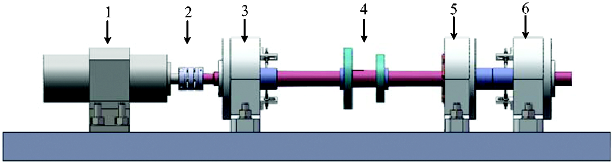
Flexible rotor test rig.
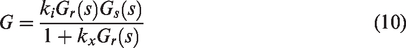
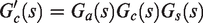
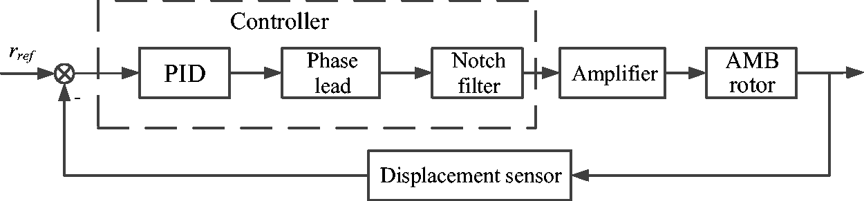
Two radial magnetic bearings are placed at both ends of the rotor. An exciter AMB in quarter spans of the rotor is used to exert different excitation on the rotor. The rotor drive end (DE) is connected with a 4 kW motor. Four eddy current displacement sensors are placed next to the two bearings, respectively, to measure the displacement of the rotor in the x and y directions. Only the non-drive end (NDE) and DE AMBs are utilized for support. Figure 2 shows the typical control diagram of the magnetic bearing system, including controller (Gc(s)), power amplifier (Ga(s)), rotor dynamic model (Gr(s)), displacement sensor (Gs(s)), bearing current stiffness (ki) and bearing displacement stiffness (kx). Parameters of the AMB experimental system, which can be directly measured, are listed in Table 1.
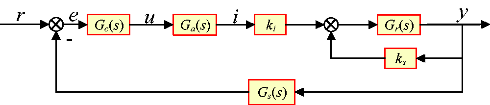
Typical control schematic diagram of magnetic bearing system.
Parameters of AMB experimental system.
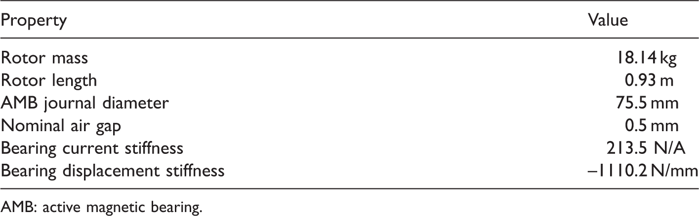
AMB: active magnetic bearing.
Modeling and dynamic analysis of flexible rotor
In this paper, the finite element (FE) method is used to model the rotor, and the motion equation of the rotor is as follows

Before analyzing the phase compensation, the modal frequencies of the rotor should be obtained. However, the FE method on the modal analysis has only a qualitative effect. Therefore, experimental modal analysis is carried out to get the real modal parameters of the rotor, 15 as shown in Figure 3.
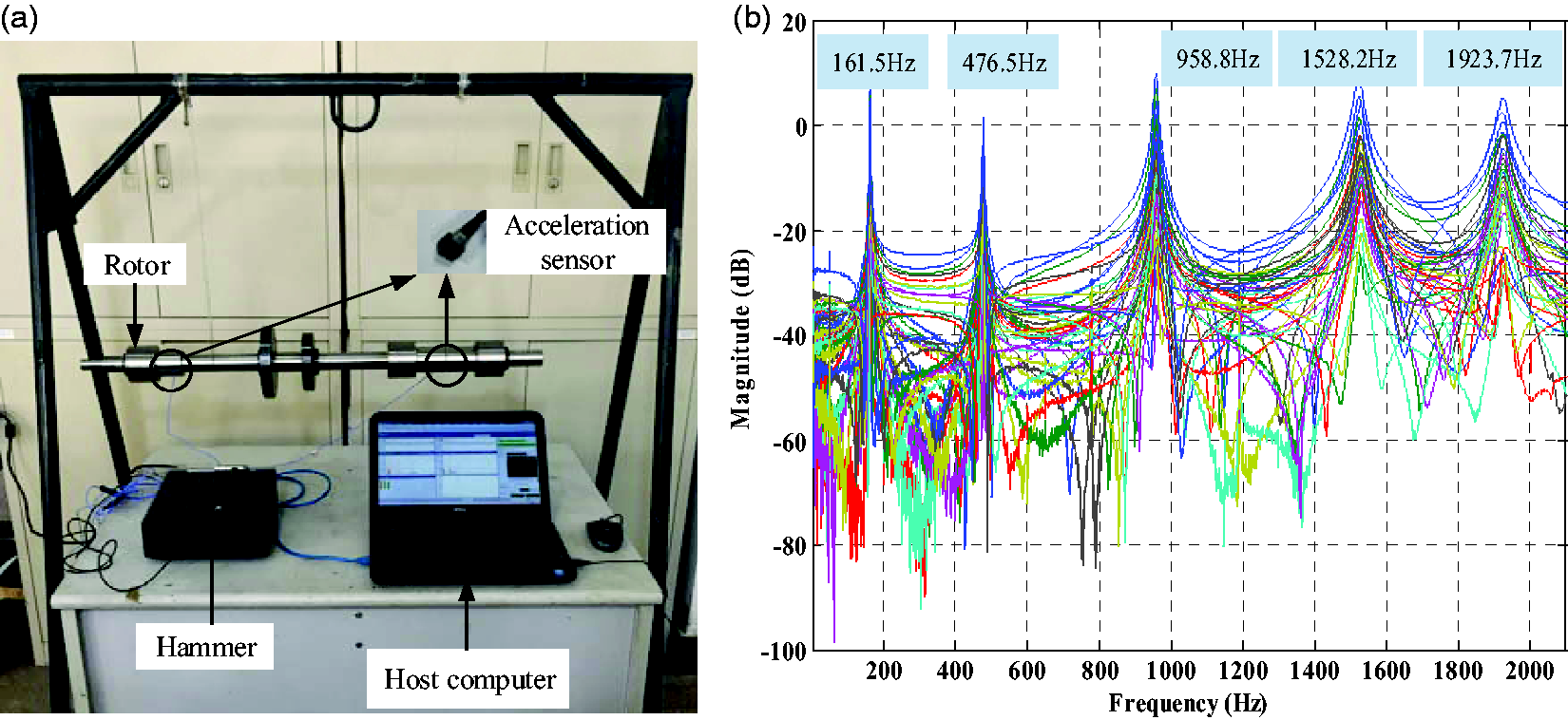
Modal test. (a) Modal impact test (b) Modal test results.
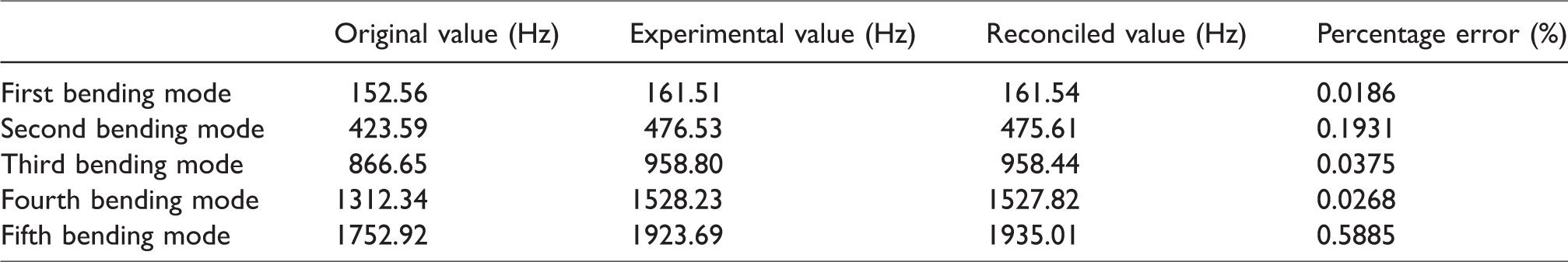
Generally, the physical parameters of the rotor, such as material density, mass and geometry are constant. However, in the FE modeling process, the elastic modulus of elements becomes an engineering assumption due to the influence of the shrink-fitting components. Thus, the elastic modulus of the rotor with shrink-fitting components can be taken as a manual parameter, and the FE model can be made approximate to the real rotor characteristics by adjusting the parameters. After lots of trial and error, the updated model modal frequencies are approximate to the modal test data as listed in Table 2.
Rotor modal frequency.
The gyroscopic effect can be ignored because the axial/radial inertia ratio of the flexible rotor is always small. An axisymmetric rotor can be decoupled on the two vertical planes without considering the gyroscopic effect. Therefore, if only the transverse vibration characteristics of a single plane (x–z plane) of the rotor are considered, its motion equations can be simplified as follows

Physical space can be transferred to modal space through the mode transfer matrix Φ (Φ = [φ1 φ2…φ2n] represents the mode shape of rotor). The mass normalized motion equation can be obtained.


Usually, the second matrix Dm is an off-diagonal matrix. If the internal damping of the rotor is small and the rotor bending modes are separated, Dm can be regarded as a diagonal matrix. To better reflect the behavior of physical rotor, low levels of modal damping (0.3%) were added.

Then, equation (3) can be described as 2n decoupling equations.

Equation (4) can be described as transfer function by Laplace transform.

Since 
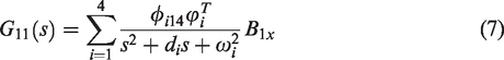
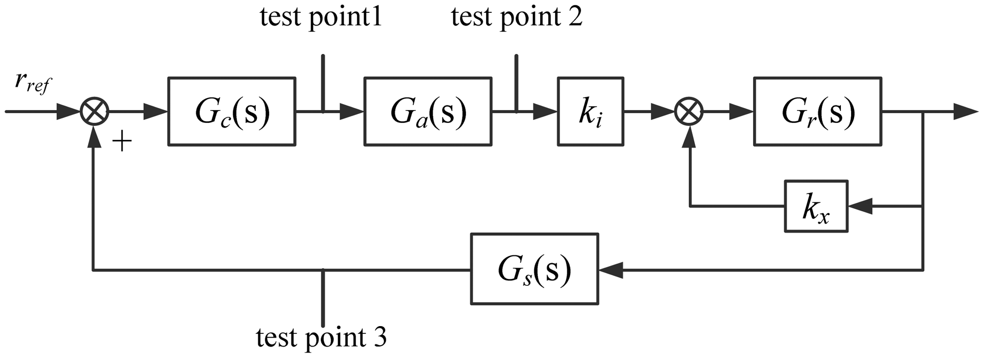
The two rigid modes and first two bending modes were preserved. According to the axial location of the displacement sensor, the DE and NDE magnetic bearing diagonal SISO transfer functions are obtained as follows

An important graphic tool for rotordynamic analysis is the undamped free–free mode shape plot, which is shown in Figure 4.
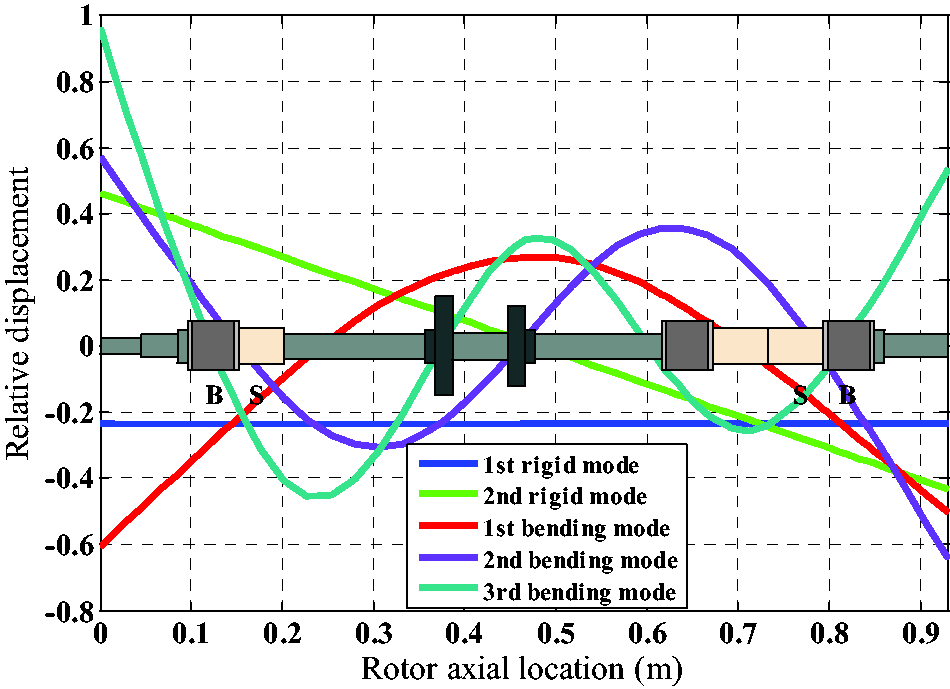
Undamped modal shape of the rotor. Rotor axial location (m).
The undamped modal shape can reflect the behavior of the rotor at the sensors and actuators position which can make it clear to us whether the distribution of sensors and actuators are reasonable. Figure 4 shows that the first bending mode of the rotor has good controllability and observability from the control perspective.
Modeling of electrical components
Power amplifier is a key component of the closed-loop system which receives control voltage and generates enough current for AMB coils.
16
The transfer function fitted to the experimental frequency response, as shown in Figure 5, is as follows
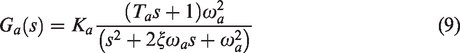
Frequency response of power amplifier.
Four eddy current displacement sensors are employed to measure the rotor lateral motion in the x and y directions. According to the parameters provided by the sensor manufacturer, the sensor can be modeled by a constant gain of 5 V/mm within the control bandwidth.
Model validation
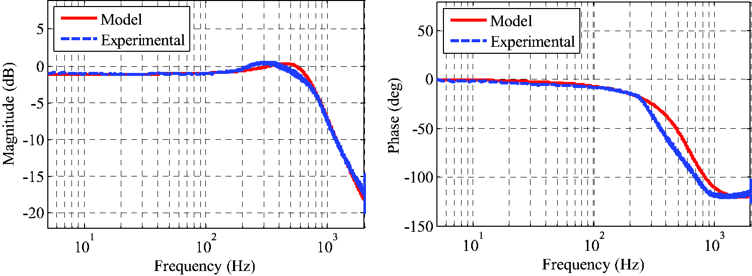
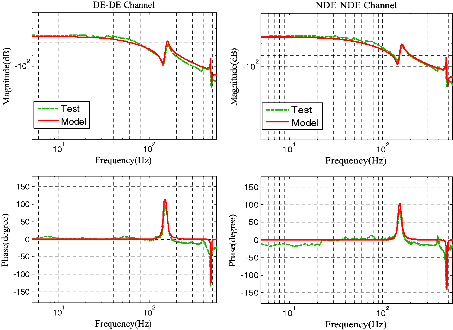
The AMB is open-loop unstable, so system identification must be conducted in closed-loop condition. Figure 6 shows the block diagram of the sweeping measurement, where Gc is the controller, Ga is the power amplifier, Gr is the rotor, Gs is the displacement sensor, ki is the current stiffness and kx is the displacement stiffness. When the rotor is suspended at the equilibrium position under PID controller at rest, the sine sweeping excitation signal is superimposed into the input end of the power amplifier (test point 1). Then, the frequency response characteristic between test point 2 and test point 3 can be obtained as shown in Figure 7, which includes dynamic characteristics of rotor, current stiffness ki, displacement stiffness kx and sensor gain. The transfer functions measured by sine sweeping are shown in equation (10).
Measurement of rotor frequency characteristic.
Comparison of the rotor model and experimental frequency characteristic.
Demonstration of the optimal damping
The amplitude of modal vibration is closely related with the external bearing damping. The larger the damping at the bending frequency, the smaller the modal vibration. Usually, the support of the magnetic bearing is taken as an equivalent spring-damping system, and its equivalent stiffness and damping are influenced by both the size of the bearing structure and the control parameters. Therefore, it is the key point that how to optimize the control parameters under the constraints of the existing structural dimensions to provide optimal damping for rotor to suppress modal vibration.
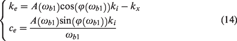
The loop from displacement output y to the bearing force Fmag can be taken as an equivalent supporting system. Then, we have

Let

Therefore, at the first bending frequency of the rotor, we have

Let
Usually, the modal vibration of the rotor is caused by the residual unbalance of the rotor at the bending mode. Thus, the unbalanced force Fu is taken as the input, and the rotor displacement y is taken as the output.
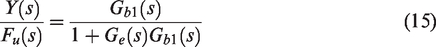
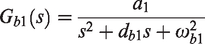

Let
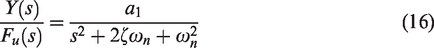
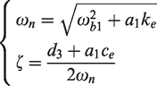
The amplitude
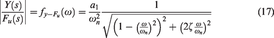
When 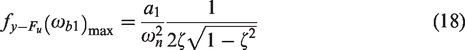
According to equation (18), the curve of resonance peak changing with the equivalent stiffness ke and the equivalent damping ce is shown in Figure 8.
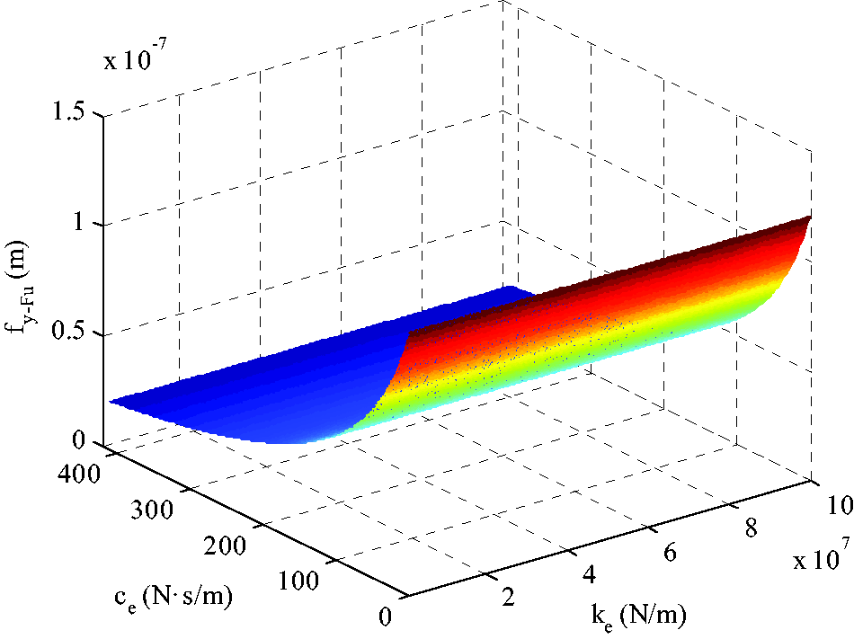
Curve of resonance peak changing with the ke and ce.
As shown in Figure 8, the resonance peak of rotor is greatly influenced by ce and is less affected by ke. Damping is usually designed to be positive value for active damping of rotor vibration.
That is, 0 < φ(ωb1) < 180°.
A(ωb1) has physical meaning, representing the gain from the displacement output y to the power amplifier current output i. According to the design parameters of the magnetic bearing as mentioned above, the output current ig of the loop gain should not exceed 2.5 A. The relationship between the first modal damping ratio ζ and A(ωb1) and φ(ωb1) is shown in Figure 9.
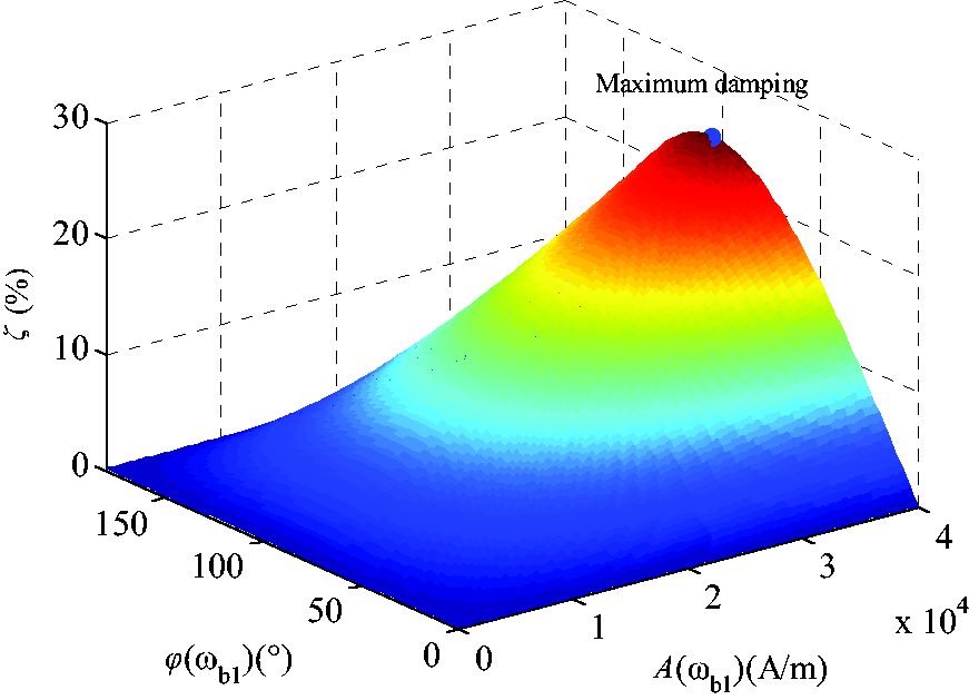
Relationship between the damping ratio and A(ωb1) and φ(ωb1).
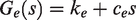
Controller design
PID controller is widely used in industrial applications, but it is difficult for the simply decentralized PID controller to solve the modal vibration problem of flexible rotor sometimes, because the lower damping level will cause severe vibration of the rotor around the bending critical speed. Therefore, in this paper, a decentralized PID controller integrated with general second-order filters is designed to provide optimal damping. In the demenstration of the optimal damping, the optimal phase is demonstrated in detail. Before the optimal phase is determined, the controller structure must be determined to make phase compensation. The PID controller can be described as follows

Thus, the frequency characteristic of
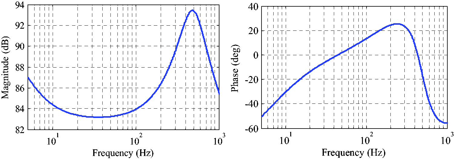
Frequency response characteristic of Gc′.
As can be seen from Figure 10, the phase at the bending mode frequency is 22° with only small phase lead. Therefore, phase lead compensator should be added to the controller at the ωb1 to obtain sufficient damping to suppress the rotor resonance vibration. The optimal phase should be determined before phase compensator design. According to ISO 14839–2, the vibration of the rotor must be less than 0.3Cmin.
17
The touch down bearing gap is generally set to be Cmin by design. Therefore
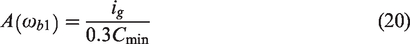
When A(ωb1) is determined, the relationship between modal damping ratio and phase φ(ωb1) is obtained as shown in Figure 11. It is indicated that the maximum damping ratio is 15.8%, and its corresponding optimal phase is 100°.
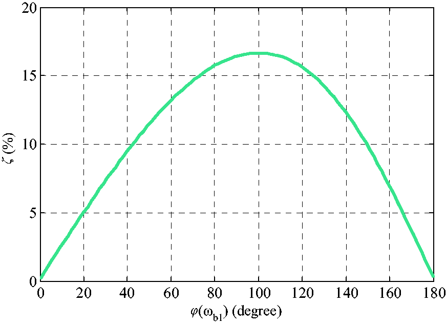
The relationship between damping ratio and phase.
As shown in Figure 10, the phase of 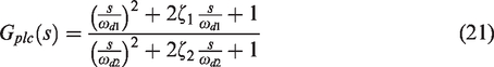
If the PBF parameters are properly selected, large phase lead can be obtained at the rotor modal frequency without affecting the amplitude of the control system. The frequency response characteristics of the phase compensator are shown in Figure 12.
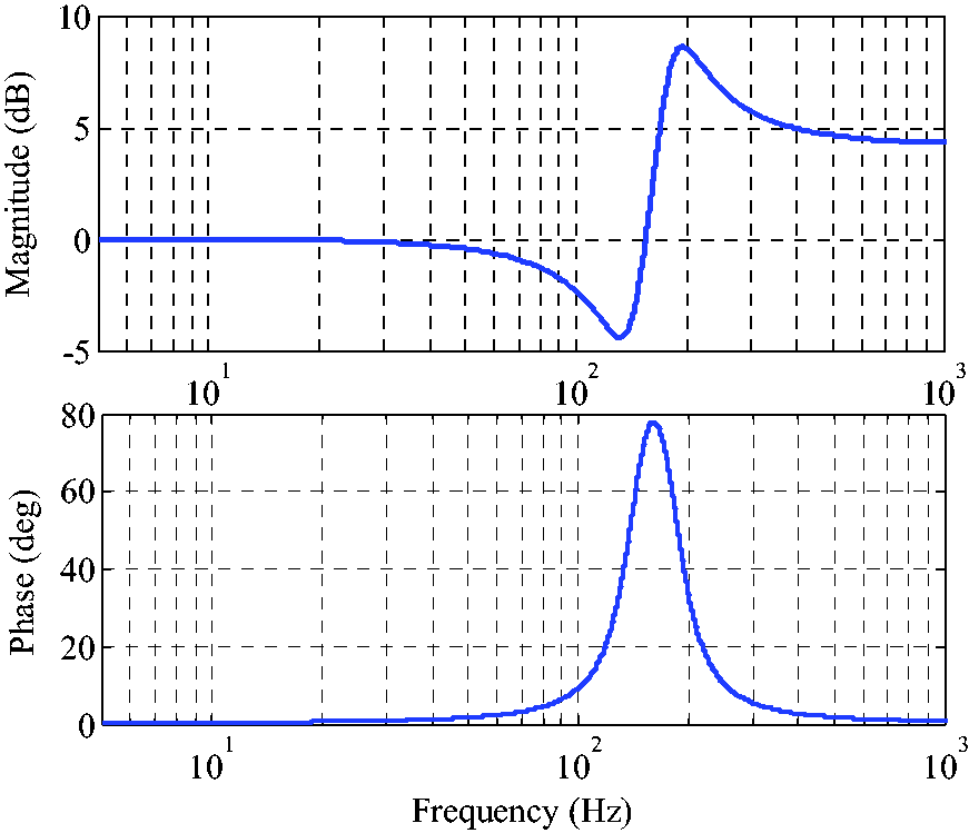
Frequency response of phase compensator.
In order to eliminate the influence of the second bending mode, a notch filter with fixed center frequency is introduced to stabilize the second bending mode in the control system.
These filters, especially the non-minimum phase filters, are very effective in controlling the modal vibration of flexible structures. But the limitation is that the system modal must have enough modal separation, and the system is approximately taken as SISO system. Finally, the whole control system can be obtained as shown in Figure 13.
The whole control system of AMB system.
Experimental validation
Figure 14 shows the experimental system of the flexible high-speed rotor with magnetic bearings. The digital controller is mainly based on TMS320C6713 and its maximum frequency is 200 MHz which contains a 12-bit A/D converter and a 16-bit D/A converter.
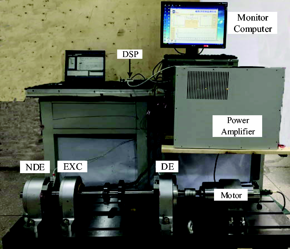
Photograph of the test rig.
Before the rotor run-up test, in order to verify performance of the designed controller, the damping ratio of rotor at the bending mode frequency is tested for the sake of safety.
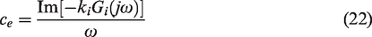
Thanks to the convenience of online testing of the magnetic bearing system, the equivalent control system of the designed controller is identified online. The system frequency response function Gi (s) is obtained by taking the displacement sensor signal as the input and the current as the output, and then the damping ratio of the system at the bending mode frequency is obtained according to equation (22).
18
The frequency response of Gi (s) with different phase compensators is shown in Figure 15, when the rotor is at rest.
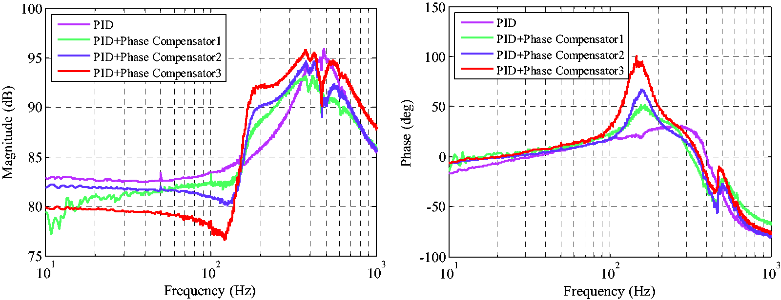
Frequency response of Gi (s).
For comparison purpose, the damping ratios with different compensators are obtained from Figure 15, as shown in Table 3.
Damping ratio with different phase compensator.
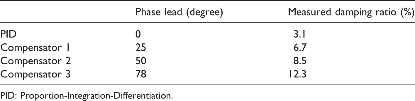
PID: Proportion-Integration-Differentiation.
As shown in Table 3, the test damping ratio is smaller than the theoretical calculation, partly due to the reason that the loop gain A(ωb1) fails to reach the theoretical maximum, and there is phase loss in the discretization process.
When enough damping was guaranteed, the run-up test can be conducted next. Figure 16 shows the magnitude of the rotor synchronous vibration. As can be seen from Figure 16, the vibration displacement has a sharp increase around the bending frequency when the rotor is suspended by simple PID without the phase lead compensator. It is not desired. Therefore, phase lead compensator must be added to enforce enough damping to suppress the rotor modal vibration. Figure 16 shows that controllers with phase compensators have obvious vibration suppression effect on the resonance. The greater the damping ratio, the lower the amplitude. Controller with compensator 3 has the lowest vibration magnitude because it has maximum damping ratio.
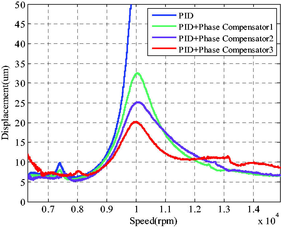
The magnitude of the rotor synchronous vibration.
However, greater damping ratio does not mean larger control current as can be seen from Figure 17. Although the controller (PID+Phase Compensator3) has the largest phase lead, the control current is smallest.
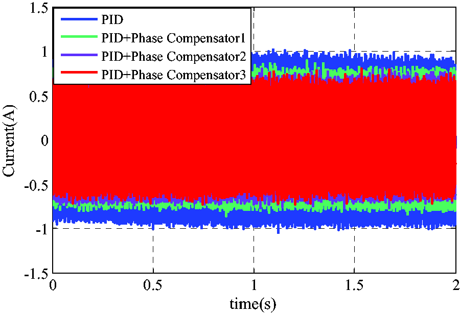
Control current nearby the bending critical speed.
Finally, the rotor resonance amplitude is within 20 µm with the optimum phase compensator and the control current around the critical speed is 0.75A. When the rotor passes the bending critical speed, the synchronous vibration displacement decrease and the rotor is stabilized up to 15,000 r/min. The rotor orbit is shown in Figure 18.
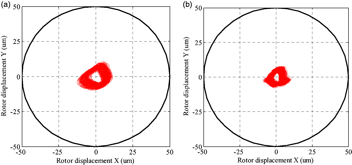
Rotor orbit of 15,000 r/min. (a) Rotor orbit of NDE (b) Rotor orbit of DE.
Conclusions
In order to meet the needs of high-speed rotating machines, rotor resonance issues must be highlighted. Magnetic bearings with simple PID controller can provide little damping for rotor resonance. This paper proposes a phase lead compensation method to provide optimum damping suppressing the vibration nearby the rotor first bending critical speed. Different phase compensators are designed. Experimental results demonstrate that controllers with phase compensators have obvious vibration suppression effectiveness. The vibration magnitude is smallest when the rotor is suspended by the controller with optimum phase compensator. Meanwhile, the control currents with optimum phase compensator have the smallest magnitude. The run-up test indicates the effectiveness and superiority of the phase compensation method.
Footnotes
Declaration of conflicting interests
The author(s) declared no potential conflicts of interest with respect to the research, authorship, and/or publication of this article.
Funding
The author(s) disclosed receipt of the following financial support for the research, authorship, and/or publication of this article: This work was financially supported by the National Natural Science Foundation of China (grant number 51575411).