
Abstract
As product quality and production capacity requirements for precision processing become higher, making machine tools smart and improving performance is becoming the trend. In terms of machine tool processing quality, tool wear and chatter vibration are the factors that most directly affect processing quality. Traditionally, operators rely on their experience in determining whether the tool is worn or if there is chatter vibration. However, experience is not quantified data. Experience does not have a uniform judgment standard and can easily lead to wrong judgment. In recent years, many scholars have conducted in-depth studies of the two aforementioned phenomenons. These studies mainly use time and frequency domains to search for phenomenon features as the determination basis. Of time and frequency domain, studies on frequency domain are the most common. However, the frequency domain method requires a large amount of calculation, and the analysis process requires an excessive quantity of data dimensions, making this method unsuitable for real-time analysis. Thus, we propose a general regression neural network analysis method based on Chua’s circuit and a fractional-order Lorenz master/slave composite chaotic system for detecting lathe tool turning chatter vibration in this study. We compared the dynamic error features produced by various fractional-order chaotic systems and chose fractional orders with more obvious feature changes. We then substituted general regression neural network categorization. Compared to the frequency domain analysis method, the method proposed in this study requires fewer data dimensions, fewer calculations, and higher efficiency. Our proposed method also has higher precision and a higher discrimination rate. The result of this study shows that our proposed method has a 100% discrimination rate for determining turning chatter vibration.
Keywords
Introduction
As industries have advanced in recent years, machine tools are being widely applied to various fields, and processing quality and efficiency requirements toward precision processing are becoming stricter. This trend has driven the improvement of various machine tools and the move toward making them smarter so that they can meet modern industrial requirements. From a turning processing perspective, lathe tool wear and turning chatter vibration are the main factors that affect processing quality. Of which, turning chatter vibration will directly affect the workpiece’s surface smoothness and processing size error, 1 which can result in loss of processing costs. Turning chatter vibration is instability in high-speed turning. 2 Traditionally, site operators identify turning chatter vibration based on their experience. However, operators may not have the same experience, so there is no quantified standard for identifying chatter and vibration. Thus, many scholars have begun studying chatter vibration identification methods and finding chatter vibration features as a basis for identification. About the researches of chatter vibration, Aslan and Altintas 3 used the currents of motor to detect the chatter dynamics. A large number of studies have been conducted on frequency domain analysis.4–6 Ishibashi et al. 7 used fast Fourier transform (FFT) to transform time domain vibration signals into frequency domain patterns. They discovered that when chatter vibration occurs, the high frequency region will have a chatter vibration frequency with very high signal/noise ratio. Lu et al. 8 transformed time domain vibration signals into a spectrum for analysis and discovered that when chatter vibration occurs, the spindle’s main frequency will migrate to a specific frequency band and the acceleration component will increase significantly. Kakinuma et al. 9 indicate that when chatter vibration occurs, transformation of the time domain signal with FFT will show that vibration component in the high frequency band increased significantly. All the aforementioned studies on frequency domain chatter vibration identification use a high signal/noise ratio acceleration component in the specific frequency band excited by chatter vibration as the quantification basis for chatter vibration identification. However, the frequency domain analysis method has one disadvantage, which is that it needs to extract a large amount of high dimension time domain signals. This makes calculation more complex. The process requires a large amount of calculation, which affects analysis efficiency, which makes this method unsuitable for real-time analysis.
To solve the aforementioned problem, we used lathe turning chatter vibration as our research topic and proposed a general regression neural network (GRNN) analysis method based on Chua’s circuit and a fractional-order Lorenz master/slave composite chaotic system. In the real physical systems, it do exist fractional order of system dynamics due to the nonlinear effects. In order to describe the nonlinear vibration in CNC to be more accurate, the fractional-order compound master/slave chaotic system is used to convert time domain vibration signals into chaotic dynamic error distribution patterns as a feature for identifying the current processing status. This feature is substituted into the GRNN for learning and categorization. The results of this study show that our proposed method can significantly increase calculation efficiency by using signal extraction with fewer dimensions and that our proposed method has a discrimination rate of 100%. Thus, this method is extremely useful for analyzing chatter vibration in machine tools.
Theoretical framework
Nonlinear Chua’s circuit
Chua’s circuit
10
is a nonlinear circuit proposed by Professor Chua in 1983 that is made up of four types of linear components, such as the inductor (L), resistor (R), capacitor (
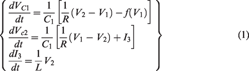
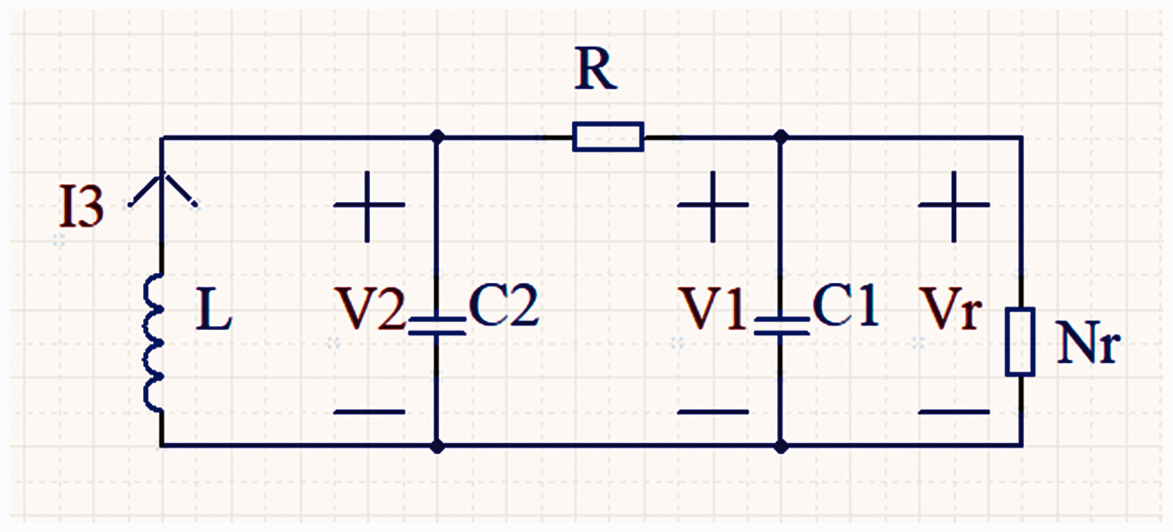
Chua’s circuit.
In equation (1),
Fractional-order Lorenz master/slave chaotic system
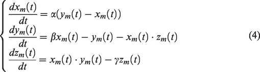
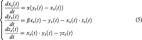
Chaos theory is a nonlinear system theory that is extremely sensitive to minute changes in input. The chaotic synchronization system can be divided into the master system (MS) and the slave system (SS), which is shown as equations (2) and (3), respectively


In the aforementioned two equations, X and Y are the status vectors, A is the
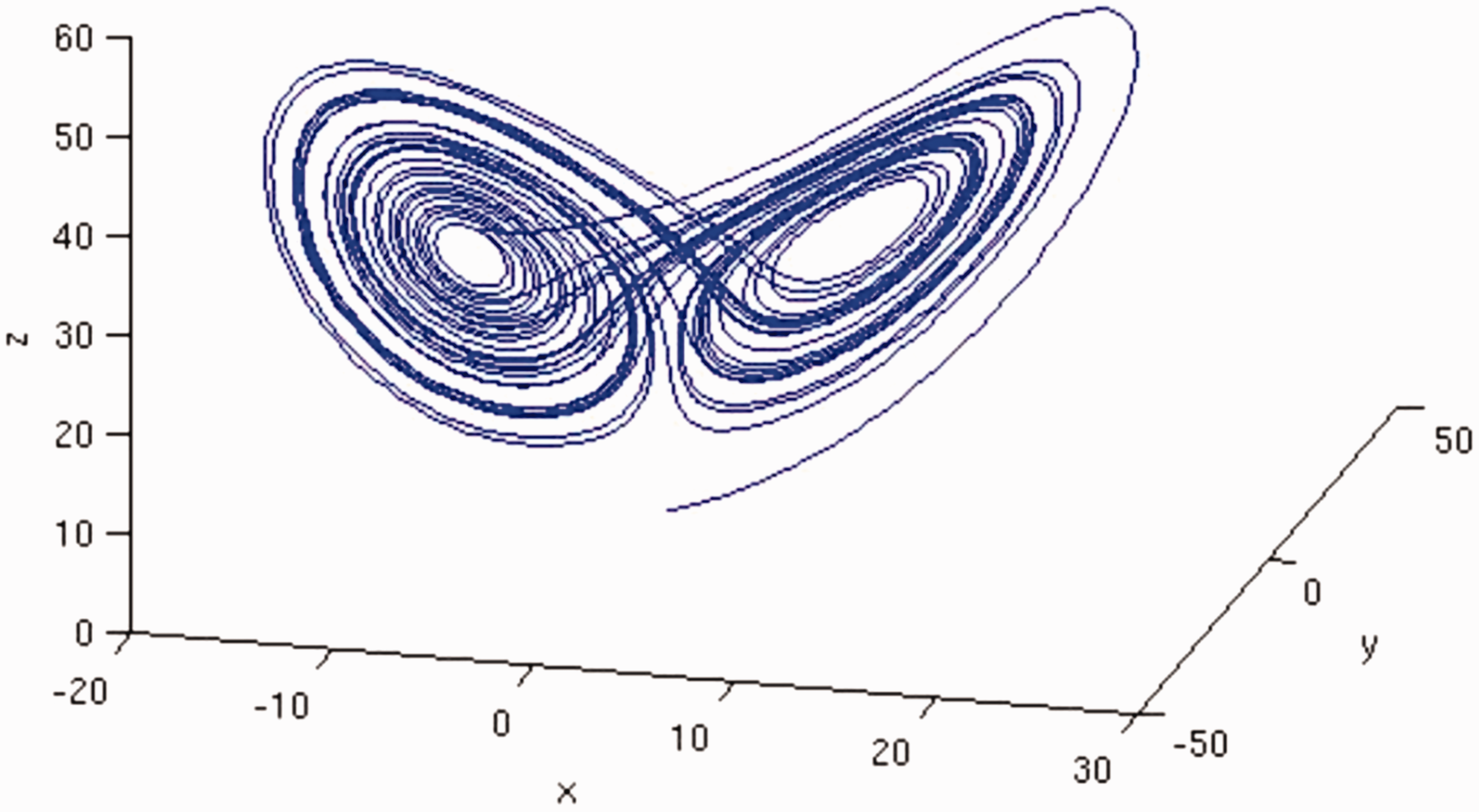
Lorenz chaotic system motion track.
Based on the study results of Yau et al.,
13
where the dynamic errors are defined as
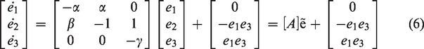
In equation (6), when the Lorenz chaotic system parameters
GRNN
The probabilistic neural network was proposed by Specht
16
in 1991. This model is based on the probability model
17
and is mainly applied to high-dimensional mapping and nonlinear prediction.
18
The GRNN is composed of the input layer, pattern layer, summation layer, and the output layer.19–21 Using pattern layer Gaussian function operation we can create output that is near nonlinear. The GRNN framework is shown in Figure 3. The output layer correlation equation is as shown in equation (8)
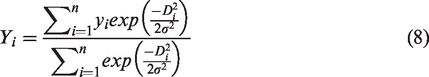
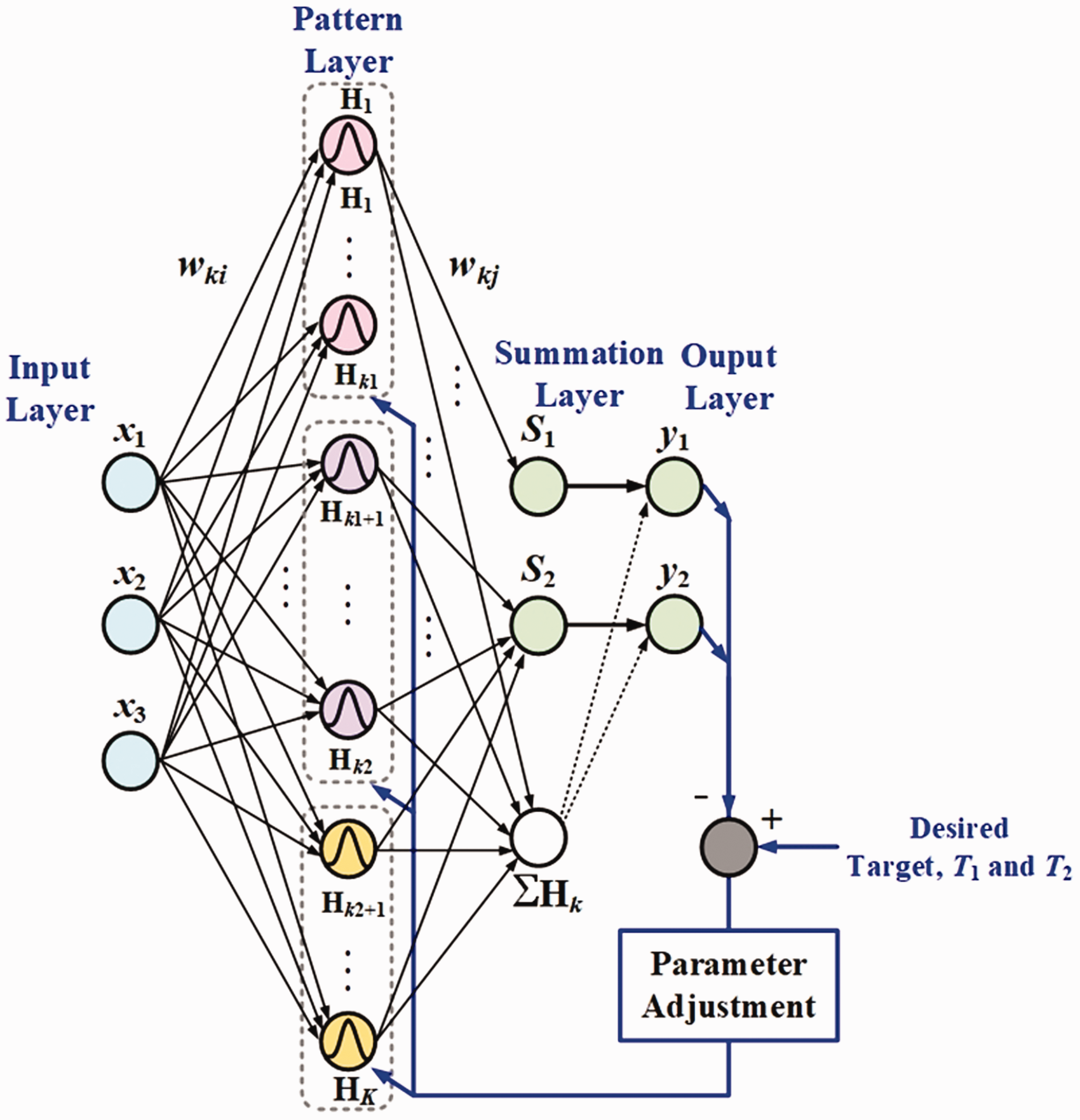
GRNN framework.
Of which

In equation (8),
Experiment framework
Time domain and frequency domain signal analysis
In this study we used the MC4200BL digitally controlled sphere CNC lathe produced by Mike Machine Industry. The 66212APZ1 uniaxial accelerometer was used for the spindle acceleration signal during turning processing. Figures 4 and 5 show the MC4200BL digitally controlled sphere CNC lathe and the 66212APZ1 uniaxial accelerometer, respectively.
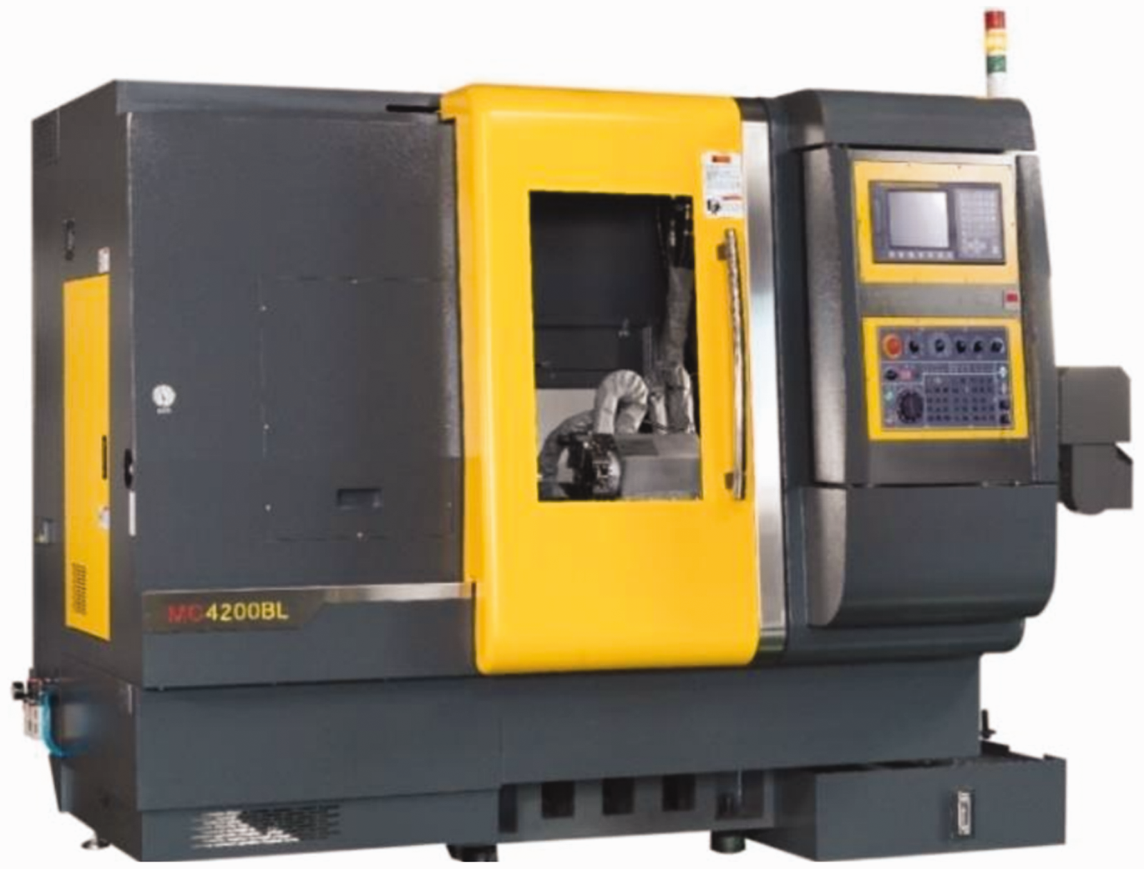
MC4200BL digitally controlled sphere CNC lathe.
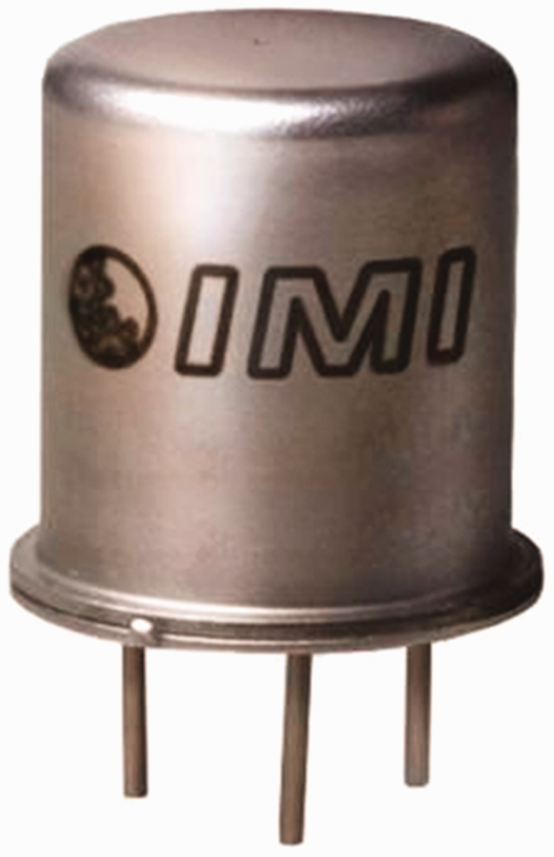
66212APZ1 uniaxial accelerometer.
We used the 66212APZ1 uniaxial accelerometer to extract the spindle acceleration signal during turning processing. The turning acceleration signal is shown in Figure 6.
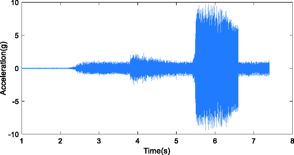
Turning acceleration signal.
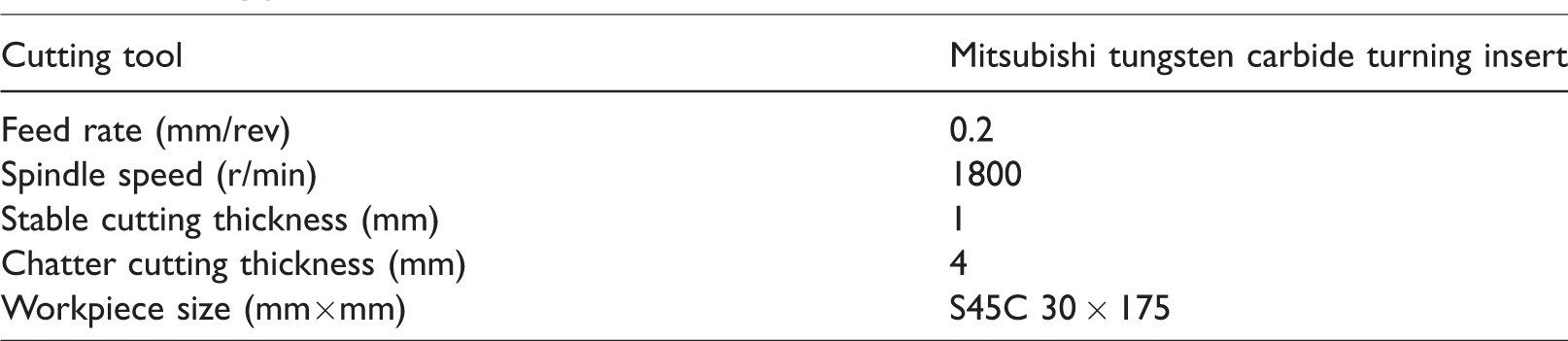
In this study we mainly analyzed the spindle idle acceleration signal, the steady turning acceleration signal, and the chatter vibration turning acceleration signal during turning processing. The framework diagram of this scheme is shown in Figure 7. In Figure 8, (a) is the idle acceleration signal, (b) is the steady turning acceleration signal, and (c) is the chatter vibration turning acceleration signal. All the setting parameters are shown in Table 1.
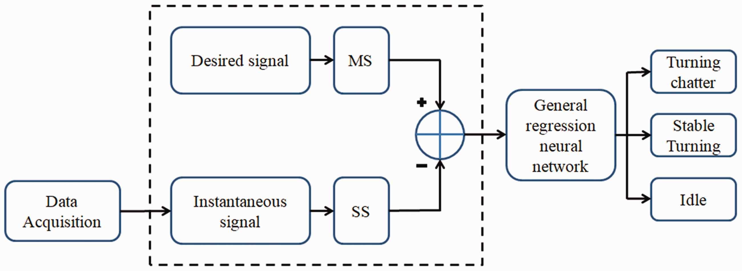
System framework diagram. MS: master system; SS: slave system.
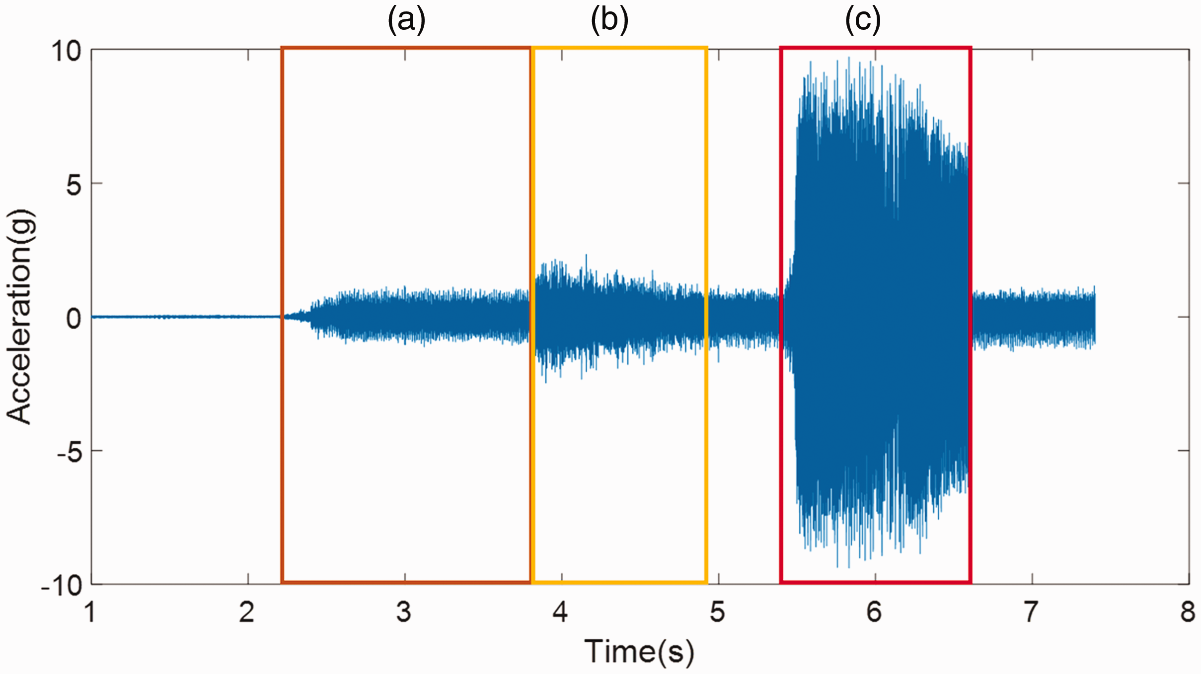
Acceleration signal of various status. (a) Idel, (b) Normal cutting, (c) Chattering.
Setting parameters.
The time domain signal’s (a), (b), and (c) segment was transformed into frequency domain signals using FFT, as shown in Figure 9.
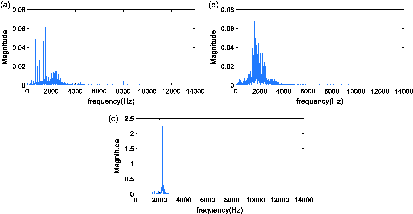
Turning acceleration frequency domain signal. (a) Idle acceleration frequency domain signal, (b) steady turning acceleration frequency domain signal, and (c) chatter vibration turning acceleration frequency domain signal.
When the cutting depth reaches 4 mm, the cutting force will be too large to cause chattering behavior due to the depth of cutting being too deep. Figure 9(c) shows that when turning chatter vibration occurs, the 2.333 kHz chatter vibration frequency will excite a signal with a higher signal/noise ratio and component. This result completely conforms to the phenomenon proposed by Ishibashi et al., 7 Lu et al., 8 and Kakinuma et al. 9 This proves that the interval acceleration signal in Figure 9(c) is the chatter vibration turning acceleration signal.
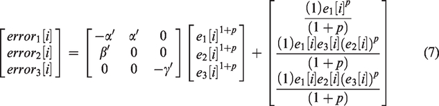
Fractional-order compound master/slave chaotic system analysis
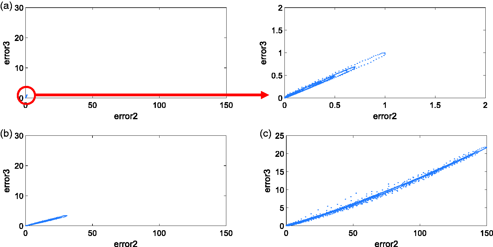
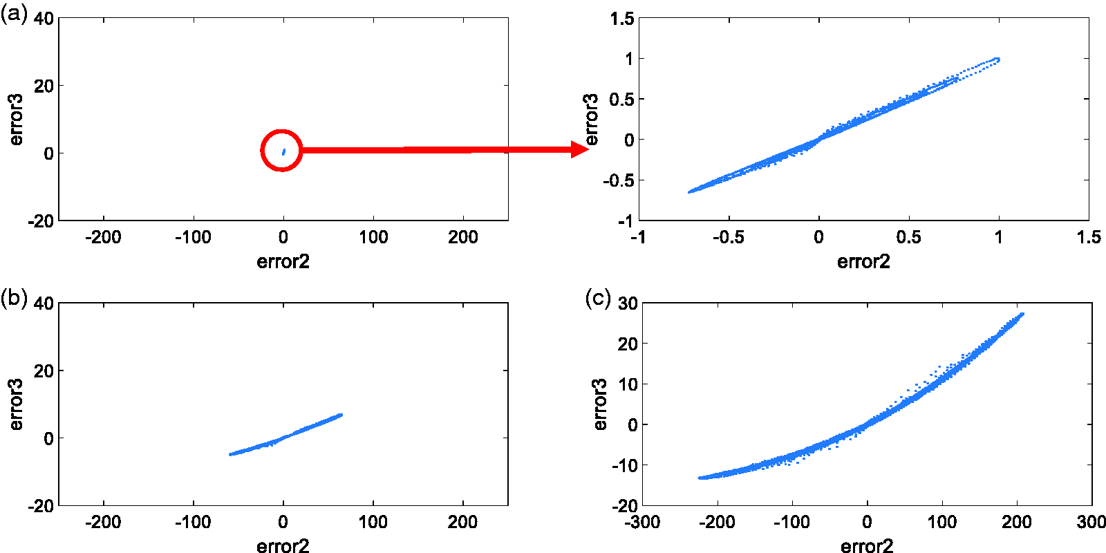
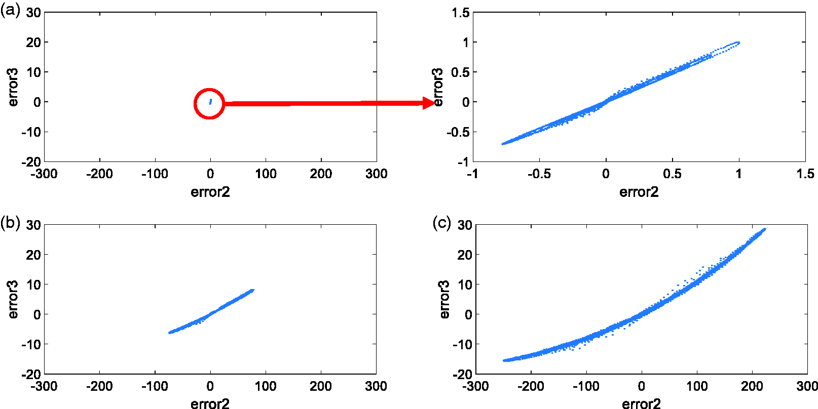
We used a fractional-order compound master/slave chaotic system that combines a nonlinear Chua’s circuit and fractional-order Lorenz master/slave chaotic system as our primary signal analysis tool. By substituting the time domain acceleration signal into the nonlinear Chua’s circuit for the first nonlinear process, then substituting the nonlinear signal into each fractional-order Lorenz master/slave chaotic system to calculate the master/slave chaotic dynamic error, we can then compare the master/slave chaotic dynamic error of each fractional order and choose the fractional order with the greatest change. This order is used as the fractional-order Lorenz master/slave chaotic system parameter. The order’s dynamic error is used as the feature basis for the signal analysis. Figures 10 to 19 show the compound chaotic system dynamic error distribution from noninteger order 0.1 to integer order 1. Generally, when chatter vibration occurs, the Error 2 and Error 3 component of the dynamic error distribution status is several times larger and more distributed than that of the other two status types. This phenomenon can be used as the standard for identifying chatter vibration. The dynamic error distribution of the noninteger order 0.1 is also more nonlinear when compared to that of other orders. Thus, we chose the compound chaotic system of noninteger order 0.1 for subsequent analysis and substituted the analysis result into GRNN for later GRNN categorization.
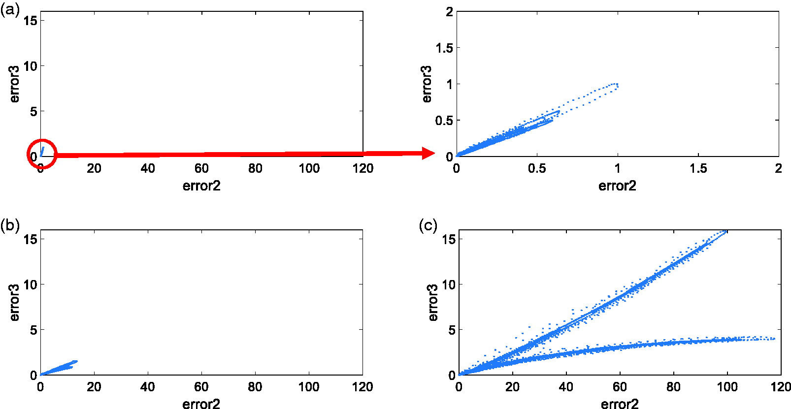
Compound chaotic system dynamic error distribution of noninteger order 0.1. (a) Idle, (b) steady turning, and (c) chatter vibration turning
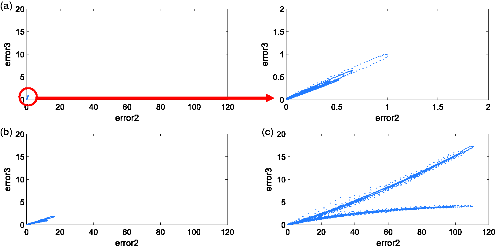
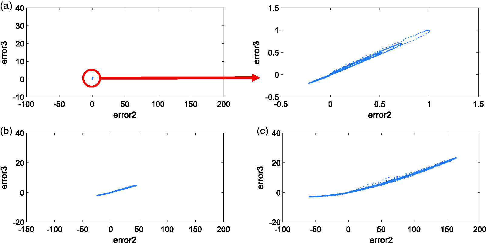
Compound chaotic system dynamic error distribution of noninteger order 0.2. (a) Idle, (b) steady turning, and (c) chatter vibration turning.
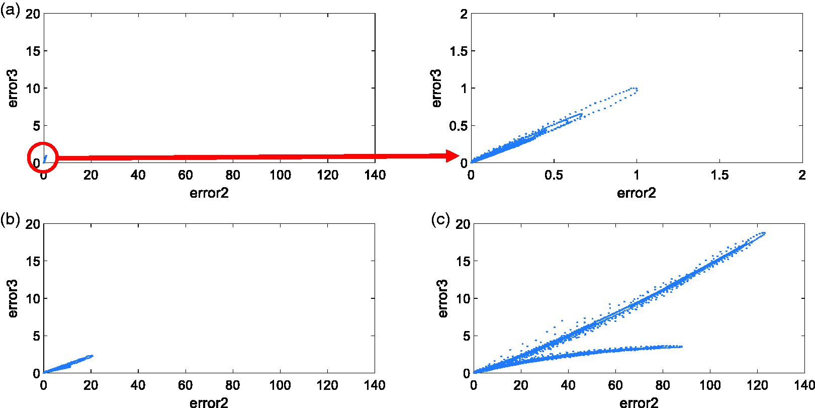
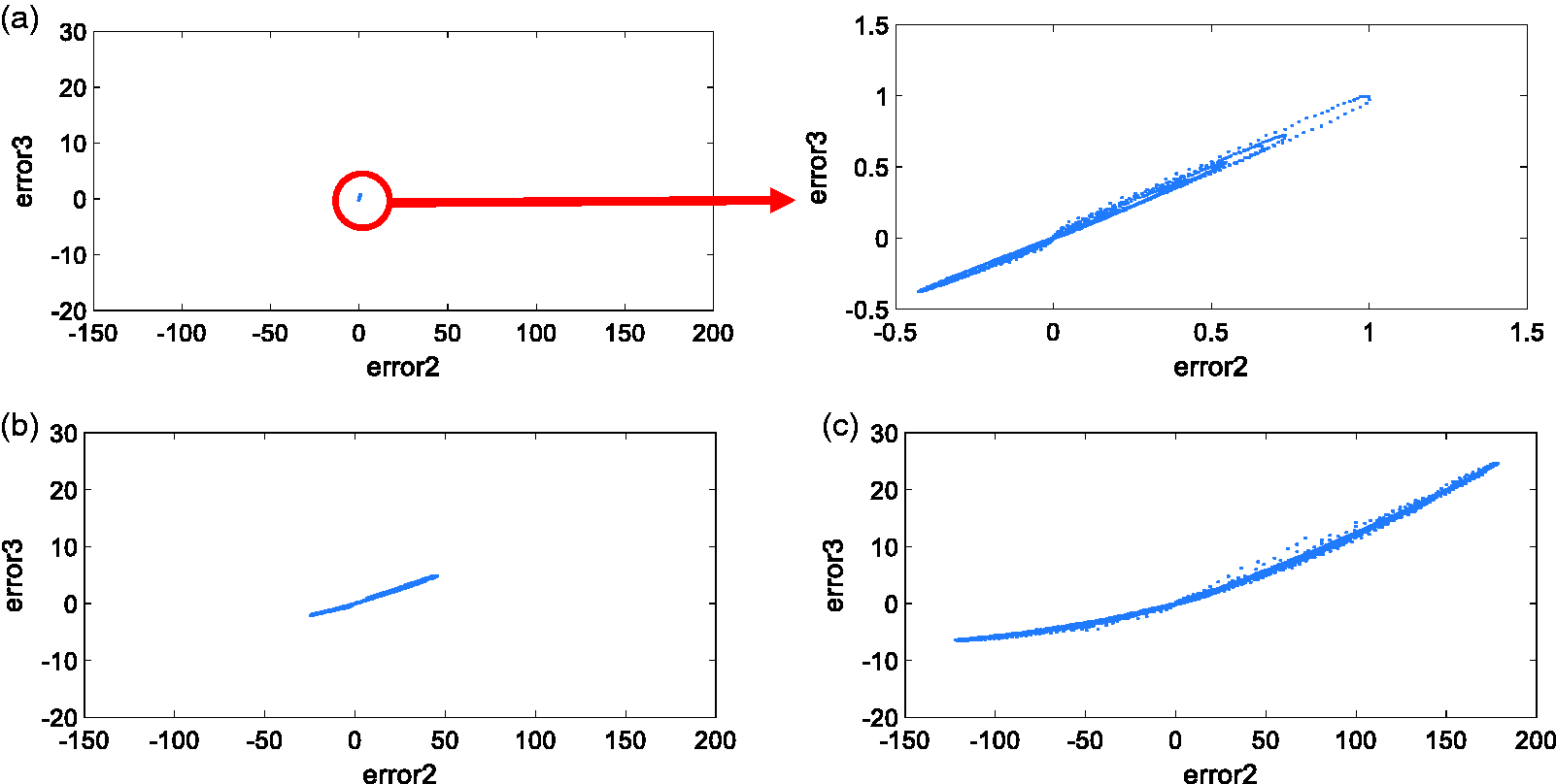
Compound chaotic system dynamic error distribution of noninteger order 0.3. (a) Idle, (b) steady turning, and (c) chatter vibration turning.
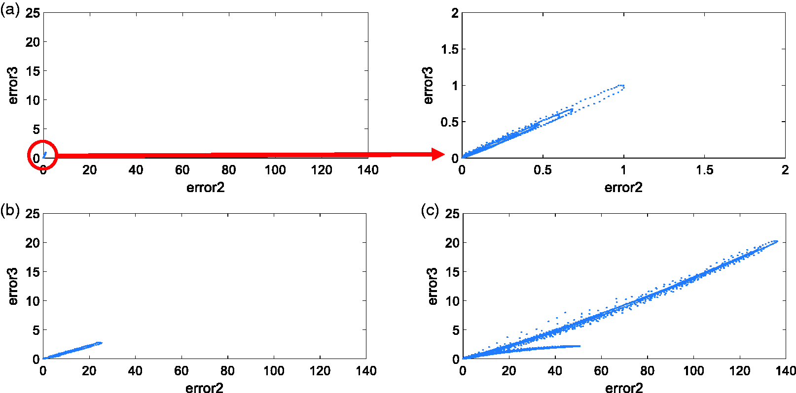
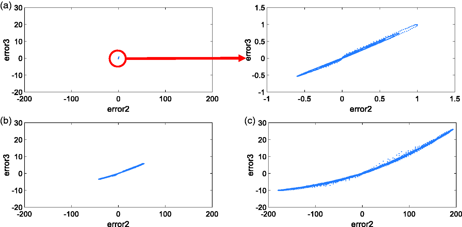
Compound chaotic system dynamic error distribution of noninteger order 0.4. (a) Idle, (b) steady turning, and (c) chatter vibration turning.
Compound chaotic system dynamic error distribution of noninteger order 0.5. (a) Idle, (b) steady turning, and (c) chatter vibration turning.
Compound chaotic system dynamic error distribution of noninteger order 0.6. (a) Idle, (b) steady turning, and (c) chatter vibration turning.
Compound chaotic system dynamic error distribution of noninteger order 0.7. (a) Idle, (b) steady turning, and (c) chatter vibration turning.
Compound chaotic system dynamic error distribution of noninteger order 0.8. (a) Idle, (b) steady turning, and (c) chatter vibration turning.
Compound chaotic system dynamic error distribution of noninteger order 0.9. (a) Idle, (b) steady turning, and (c) chatter vibration turning.
Compound chaotic system dynamic error distribution of integer order 1. (a) Idle, (b) steady turning, and (c) chatter vibration turning.
GRNN categories
In this study, we used the GRNN as the postsignal analysis smart categorization tool. Error 2 component from the aforementioned noninteger order 0.1 compound chaotic dynamic error was substituted into GRNN. PSO was used to train the optimal smoothing parameter. Figure 20 shows the GRNN training result.
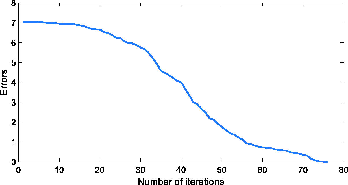
GRNN training result.
Figure 20 shows that on the 75th PSO iteration, the error converged to the global optimal solution. That is, the
The turning surface of steady state.
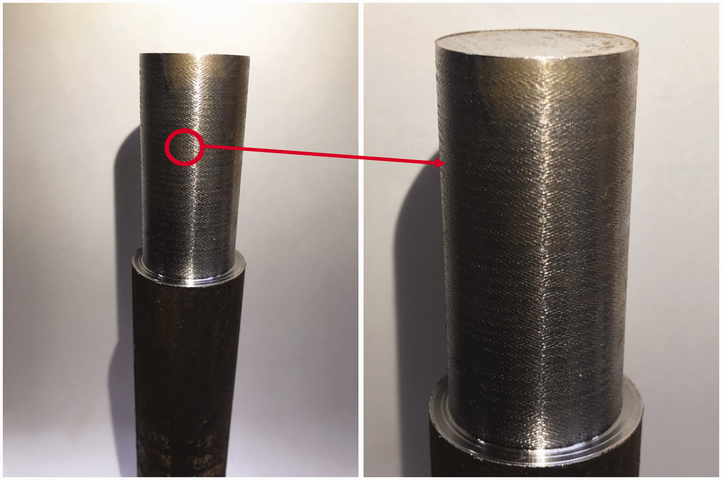
The turning surface of chattering state.
GRNN categorization result.
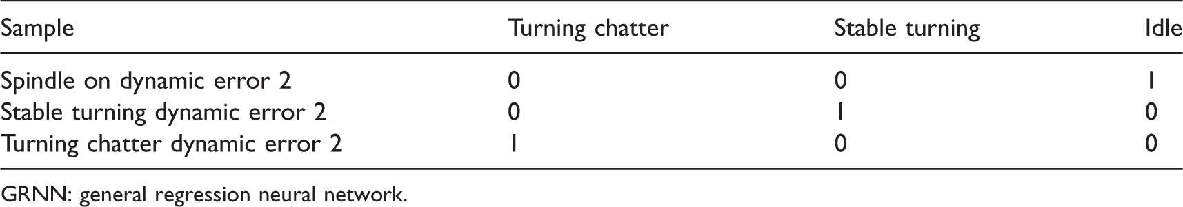
GRNN: general regression neural network.
We used a fractional-order compound master/slave chaotic system for analysis and used GRNN for categorization. The above table 2 shows that after the categorization result substituted the idle signal into the GRNN, the idle item was 1, the steady turning signal was 1, and the chatter vibration turning signal was 1. This indicates that the process can accurately categorize idle, steady turning, and chatter vibration turning. Table 1 shows that the categorization accuracy reached 100%. This proves that the method proposed in this study is feasible and can be used to great effect on identifying chatter vibration.
Conclusion
In this study we used a lathe machine tool as the basis to study turning chatter vibration. By comparing the dynamic errors produced by different fractional-order compound master/slave chaotic systems, we were able to extract an order with more obvious change. The dynamic error of this order was then used as the feature for identifying chatter vibration. GRNN was then used to smartly and effectively categorize the feature. Compared to traditional frequency domain analysis methods, the method proposed in this study extracts less data and requires fewer calculations. Thus, under the premise of not affecting accuracy, the calculation efficiency can be significantly increased. This study is the first to use compound fractional-order master/slave chaotic system combined with GRNN to analyze chatter vibration. This very novel method has been verified by this study to have 100% discrimination. This means that the method proposed in this study is very practical. Because this method has simpler operation and superior calculation efficiency, it can be integrated into embedded systems. Portable chatter vibration diagnostic devices can be developed to make application of smart analysis and categorization system proposed by this study more convenient.
Footnotes
Declaration of conflicting interests
The author(s) declared no potential conflicts of interest with respect to the research, authorship, and/or publication of this article.
Funding
The author(s) disclosed receipt of the following financial support for the research, authorship, and/ or publication of this article: The authors would like to thank the Ministry of Science and Technology, Taiwan, for financial support of this project under Contract No. MOST 104-2221-E-167-001 and MOST104-2622-E-167-019-CC3.