
Abstract
In order to reduce the effect of delayed fracture of high-strength bolts on train operation and structural safety, a non-destructive testing method for axial force of high-strength bolts in railway steel bridges is studied to identify and replace over-twisted bolts in time, so as to reduce the probability of delayed fracture caused by external factors. Based on the acoustic-elastic effect theory, considering the uneven internal stress distribution of bolts in service, in this paper, the bolt force area is differentiated into three regions: the nut, the screw and the thread; the author calculates the ultrasonic flight-time in different bolt stress areas and revises the impact of bolt elastic deformation and temperature by external force on sound speed and puts forward a more precise measurement method of axial force of bolt in service. According to the results of the test, the relative error between the ultrasonic measurement result and the displayed value of pressure sensor is less than 10%.
High-strength bolt is one of the main connections of large steel structure facilities including railway bridges. The high-strength bolts in our country have been developed from 40 B to 20 MnTiB and 35 VB, which have been widely used till now. The inspection of engineering practice in the last 40 years showed that the high-strength bolts of these two materials can meet the requirements of usage. In recent years, chances of delayed fracture of high-strength bolt are increasing due to many factors. Eleven railway bridges with the disease of high-strength bolts suffering from delayed fracture were studied, in which three bridges suffer from more than 50 sets of bolt fracture, three bridges suffer from over 10 sets and less than 50 sets, and another five bridges less than 10 sets. Thousands of bolts are usually used on each bridge, so the overall fracture ratio is extremely low. Although it is not enough to cause the node disconnections, for the flat or transverse connections at the top of the limit line, bolt fracture may cause invasion or even hit trains, so special care should be taken. In general, the inducement of delayed fracture of high-strength bolts can be divided into internal factors, mainly including material and manufacturing defects of high-strength bolt as well as construction errors, and external factors, mainly including environmental factors such as temperature, humidity and PH value as well as the over-limit of construction pre-tightening force. According to the regulations of construction of high-strength bolt connection in railway steel bridge, the method using definite torque wrench for construction torque control in the process of the railway steel bridge erection is mature technology and widely used. However, limited by the tools used and other factors, the construction torque control is inaccurate. There will be an increasing risk of a delayed fracture when high-strength bolt working pre-tightening force exceeds the design value. In order to reduce the effect of delayed fracture of high-strength bolts on train operation and structural safety, it is necessary to study non-destructive testing method for axial force of high-strength bolts in railway steel bridges to identify and replace over-twisted bolts in time, so as to reduce the chances of delayed fracture caused by external factors.
Based on acoustic-elastic effect, ultrasonic measurement technique on bolt axial force is a fast and non-destructive measuring method which has attracted attention from domestic and abroad scholars.1–8 Hehman et al.9,10 developed the automatic electromagnetic acoustic transducer and correlative algorithms, which can be used to measure the stress value of the sample. Jhang et al. 11 used phase detection technology to measure travel time of ultrasonic wave, which reduced impacts of noise jamming and improved the measurement accuracy compared with traditional methods. Jaglinsld and Nimityongskul 12 adopted resonance ultrasonic spectroscopy to measure the natural frequency of the specimen by adjusting the input frequency so as to calculate the modulus of rigidity and elasticity of bolts in small molding-die engine; thus, they provided the research basis and an example for the calibration of bolt material constants. Hirao et al. 13 developed a tool which can simultaneously emit and detect longitudinal and shear waves to explore non-contact measurement and further improved the measurement method of bolt axial force. Koshti 14 tried to measure the stress of bending bolt by ultrasound, and Clark et al. 15 also focused on the engineering application research of ultrasonic stress measurement and obtained a series of results. Because of the assembly characteristics of screw caps, screws and nuts, the internal stress distribution of the bolts in service is uneven, and the propagation velocities of ultrasonic waves are different in different stress areas. But the characteristics of high-strength bolts in service are seldom considered in current ultrasonic measurement method of bolt axial force. On the basis of acoustic-elastic effect, considering, respectively, the flight-time of ultrasonic wave in different stress distribution areas of high-strength bolts, a new method for measuring bolt axial force is put forward and verified by real experiments.
Measurement principles of axial force of high-strength bolt in service
According to the principle of acoustic-elasticity, the stress change of solid dielectric in the direction of ultrasonic longitudinal wave will cause the corresponding change of longitudinal wave velocity, which provides a theoretical basis for measuring material stress by acoustic method. The axial force of bolts can be measured by the change of sound velocity caused by the acoustic elastic effect. The propagation velocity of longitudinal wave propagating along the force direction is shown as formula (1).

Thereinto, we set material constant

and substituting it in formula (1), we get

According to the formula, by means of measuring ultrasonic flight-time, the speed of sound can be calculated on the basis of knowing bolt length, and then the internal axial force of bolt can be deduced. However, due to the uneven internal stress distribution of bolts in service, the ultrasonic flight-time is different in different areas, so it is imprecise to establish relation curves of sound speed and stress only by the same formula
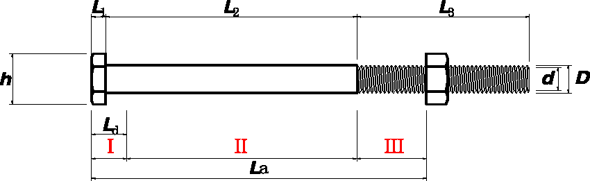
According to the characteristics of stress distribution, the bolt can be divided into three regions: I, II and III, as shown in Figure 1. Region I is the stress area of the nut, Region II is the stress area of the screw and Region III is that of the thread. Axial length of the nut is L1 and h is the diameter; the length of screw is L2 and D is the diameter; the length of thread is L3 and d is the diameter. The total length of stress area is La and the length of Region I is Ld.
Calibration of bolt size.
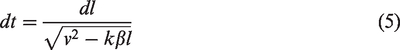
Suppose the calculated length

Then substitute it into formula (3) and take differentiation
By the integral of
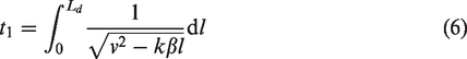
In the formula,
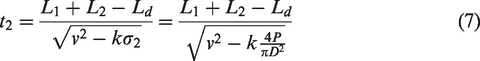
Suppose the stress distribution high-strength blot in service in area II is an approximate average, we get ultrasonic flight-time in region II
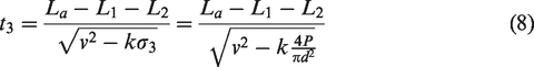
Suppose the stress distribution high-strength blot in service in region III is an approximate average, we get ultrasonic flight-time in region III
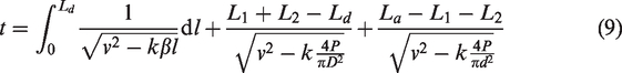
So ultrasonic flight-time in high-strength bolt in service is
By considering bolt elastic deformation by external force, we modify formula to
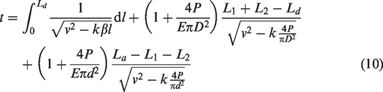
Compared with the bolt total length,
Considering the effects of temperature on sound speed
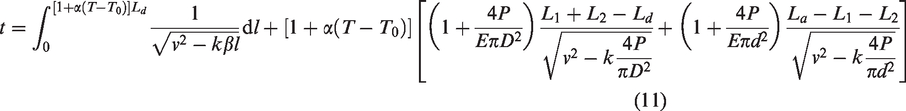
T0 is the initial temperature, T is the experimental temperature,
The parameters k, β and L d can be obtained by calibration. According to formula (11), as long as ultrasonic longitudinal wave flight-time t of bolt in the stress state is measured, we can get the force P of high-strength bolt. According to theoretical deduction above, the ultrasonic measuring method for axial force of high-strength bolt can be obtained in a higher precision.
Simulation analysis of stress of high-strength bolt in service
In order to accurately analyze the axial force distribution of high-strength bolts in service, the Pro/Engineer business software is adopted to model in equal proportion, and Abaqus.2017 version commercial software is imported for finite element analysis. The size of the high-strength bolt specimens is in accordance with the actual size, in which bolt diameter D = 22 mm, thread diameter d = 20 mm, total length L = 300 mm and the size of each part of bolt L1=10 mm, L2=170 mm and L3=120 mm. Bolt and metal sleeve are assembled to fully simulate the stress state of high-strength bolts during service, as shown in Figure 2.
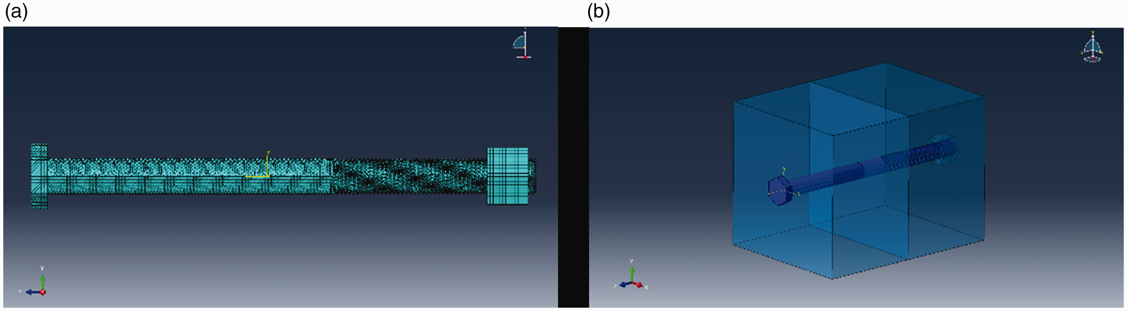
Assembly model diagram of single high-strength bolt. (a) Grid division; (b) assembly model diagram.
The specimen is set as isotropic material, and the SOLID45 unit is used for grid division. In order to ensure the accuracy of calculation, a unified tetrahedral mesh is adopted for the model, with 140,000 cells of grids and 2 mm of infinitesimal, as shown in Figure 2(a). Young's modulus of the material EX = 200 GPa, Poisson's ratio NUXY = 0.3. The specimen is set in elastic-plastic deformation, with two rigid slabs fastened together with bolts and nuts; the boundary conditions are simplified to the bottom of the nut without any deformation constraint according to the actual situation, and then a distributed load with total load of –100 kN is applied at the top end of the bolt.
The misses stress distribution of bolts is shown in Figure 3. According to the figure, the stress distribution of the high-strength bolts in service is different, which can be divided into three regions on the whole. The transition path of ultrasonic wave usually runs along the central axis of the bolt and positive stress on the path is output. The law on the change of stress on the path under different external loads is given in Figure 4.
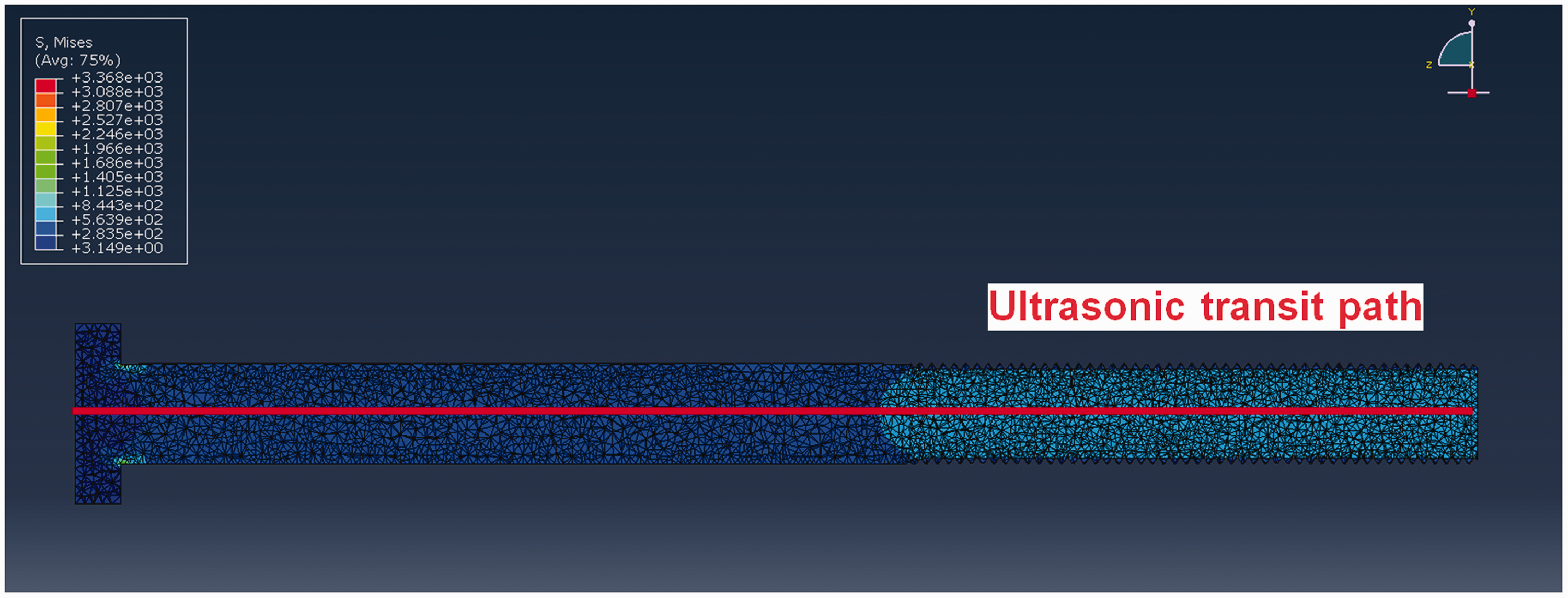
Misses Stress distribution of blots simulated by Abaqus.
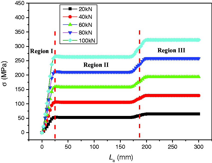
Stress distribution under different loads.
From the figure, the stress of high-strength bolts in service is obviously divided into three regions. The stress increases linearly in Region I, but in approximately uniform distribution in Regions II and III. With the change of external loads, there is no change in the stress variation of bolts, and the overall stress amplitude increases gradually with the increase of loads. According to finite element analysis, we can get L
d
= 25 mm and the relation between
Axial force measuring experiment of high-strength bolt in service
Axial force measurement experiment was carried out on 10.9 M22 × 300 high-strength bolts. The ultrasonic testing system SNAP-5000 (Ritec, USA) is used to drive with ultrasonic longitudinal wave signal, with 5 MHZ of frequency and 20°C of temperature, recording precisely longitudinal wave flight-time by using oscilloscope. The test principle is shown in Figure 5 and the test image in Figure 6. First, randomly select three bolts for calibration in specimen to be tested, 10 kN as load steps, loading progressively from 0 kN to 100 kN to measure ultrasonic flight-time of calibrated bolt. Through a precise quantitative tension test, we can get the accurate corresponding graph of sonic time-load, as shown in Figure 7. According to the figure, with the increase of loads, axial force is linearly related to sonic time. After calculating, calibration coefficient is k = 1412.38 and we can adopt the results of finite element simulation in which L
d
= 25 mm; the relation between
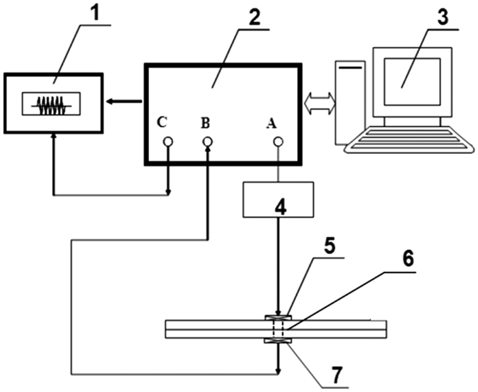
Axial force testing principles of bolt in service. 1: oscilloscope; 2: host; 3: computer; 4: prefixed attenuation and low-pass filter module; 5: ultrasonic transducer; 6: specimen of bolt in service; and 7: ultrasonic transducer.
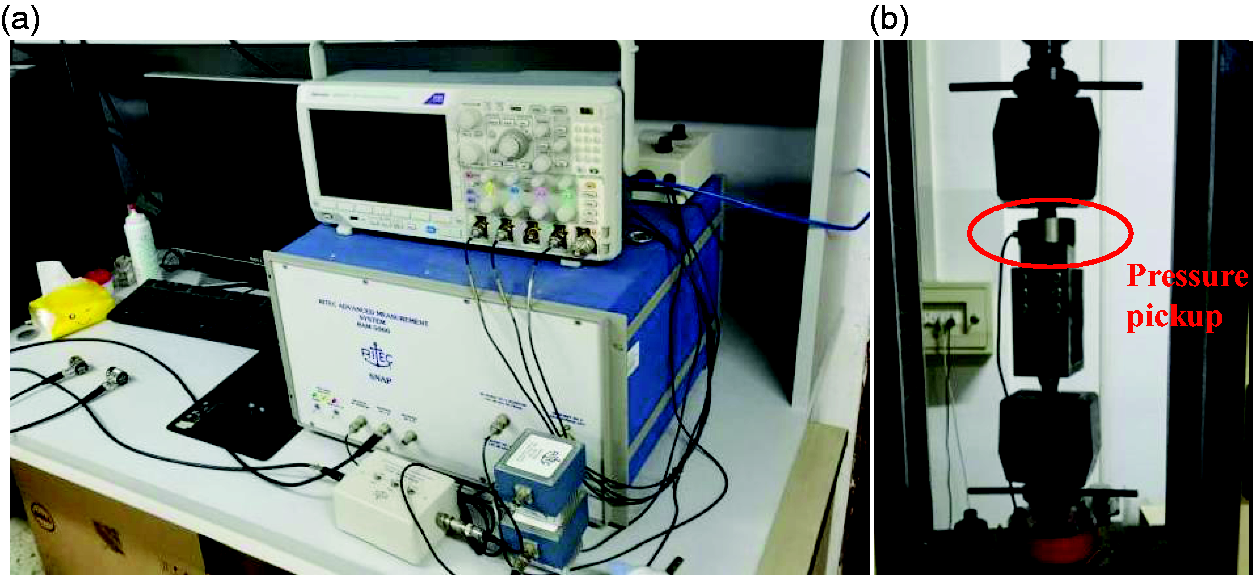
Experimental testing. (a) Ultrasonic testing equipment; (b) bolt is loading.
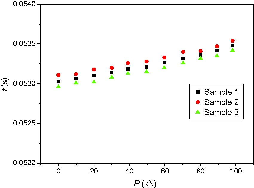
Graphs of sonic time-load after calibrated by system.
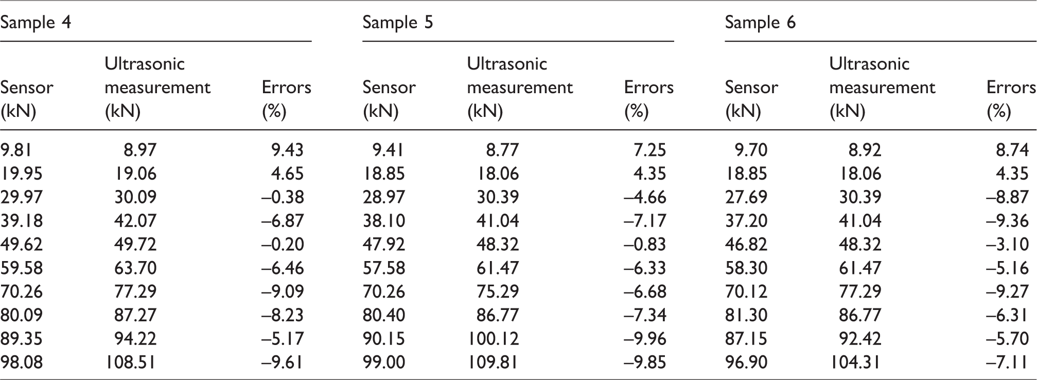
Then select another three bolts for calibration in specimen to be tested, 10 kN as load steps, loading progressively from 0 kN to 100 kN. After each loading, we measure ultrasonic flight-time to calculate axial force of bolts. Using the displayed loads of pressure sensor on bolt as the actual axial force value, the relative error of the ultrasonic axial force measurement is calculated, and the results are shown in Table 1. In the three groups of experiments, the maximum relative error of axial force ultrasonic measurement is –9.96%, and the minimum relative error is –0.2%. The results show that this method can be used to effectively test the axial force of bolts in service under different external loads, and the relative error is not more than 10%.
The ultrasonic measurement results of bolt axial force under different loads.
Conclusion
Based on the acoustic-elastic effect theory, considering the uneven internal stress distribution of bolts in service, in this article, in which the bolt force area is differentiated into three regions, the author, respectively, calculates ultrasonic fight-time in different bolt stress areas, revises the impact of bolt elastic deformation and temperature by external force on sound speed and puts forward a more precise measurement method of axial force of bolt in service. The calculation method of a test was carried out. Through the test, the relative error between the ultrasonic measurement result and the displayed value of pressure sensor is less than 10%. By using this method, the bolt axial force can be effectively measured when the high load or low load is unknown.
Footnotes
Declaration of conflicting interests
The author(s) declared no potential conflicts of interest with respect to the research, authorship, and/or publication of this article.
Funding
The author(s) disclosed receipt of the following financial support for the research, authorship and/or publication of this article: This work was financially supported by the Foundation of Beijing Jiaotong University (no. 2016RC023), National Natural Science Foundation of China (no. 11402018), the Research and Development Plan for Science and Technology of China Railway Corporation (no. 2016G003-G).