
Abstract
The baseline signal in structural inspection based on guided waves is difficult to be obtained under varying environmental conditions. To guarantee the precision of damage identification, developing baseline-free damage detection methods is significant in practical structural monitoring work. Conventional instantaneous baseline measurement needs a large number of PZT transducers. In this paper, a novel damage identification method for plate-like structures based on distance compensation is proposed to overcome this shortage. Combining with the concept of instantaneous baseline measurement, pitch-catch pairs of different propagation distance can be compared together to reveal the health information of the measured paths. This method overcomes the drawback of instantaneous measurement, which can only monitor the paths of identical wave travelling distance. Both simulations and experiments are conducted to validate the proposed method. Using this method, the influence of damage size and classification on amplitude variation is discussed. Finally, a baseline-free damage imaging technique is developed based on amplitude loss ratio of the first arriving wave package. The result shows a good agreement of the predicted result and the real damage location.
Introduction
Structural health monitoring (SHM) technique based on guided waves (GWs) has gained much attention in various applications such as aged aircrafts1,2 and civil infrastructures.3,4 Even though the rotor-bearing systems are operated in complicated conditions,5–8 GWs also have the potential to be applied in their health assessment. 9 Because of the ability to directly notice the deviation in a material’s module and achieve the investigation of a whole targeted area in a single inspection process, GWs have been used in many types of structures such as plates and pipes.10,11 In fact, GW-based approaches have shown great potential to reduce the risk of failure and prolong the lifespan of interrogate structures. In general, most of the health-monitoring approaches are based on the comparison of testing data to baseline data.12,13 Each variation in wave field of examined structures is considered as a result of material failure or structural damage. However, environmental variations have also a significant effect on wave propagation. Baseline signals-dependent damage detection methods will encounter precision loss in the practical applications. Therefore, baseline-free methods are significant to improve the robust of damage identification and avoid the influence of environmental variability.
Since damage is not the only factor that can induce signal changes, health assessment should be less dependent on the pristine signal. Among the baseline-free methods, time reverse processing (TRP) has been widely studied.14–16 In TRP, an input signal can be focused at an excitation point if an output signal recorded at another point is reversed in the time domain and emitted back to the original source point. The reconstructed signal is compared to the original excitation. When nonlinearities are introduced into the system by damages, linear reciprocity breaks down and the difference between the two signals indicate the changes of structural health condition. Park 14 proposed a time reversed Lamb wave (TRLW)-based damage detection technique to identify the delamination in composite laminate. Watkins and Jha 15 presented a modified time reversal method in which the transducers act as both actuator and sensor. Miao et al. 16 introduced a probabilistic damage-detection imaging approach for multiple damage detection in aluminum plate. In general, baseline-free method using TRP is relatively complicated and the selection of reversed time domain window is rather difficult.
Nonlinear ultrasonic modulation can be applied in reference-free fatigue damage detection technique. Nonlinear ultrasonic techniques look for nonlinear characteristics of ultrasonic wave propagation such as harmonics and modulations generated by defects. Lim et al. 17 used two excitations of a low frequency and a high frequency to apply on a structure. The crack-induced in spectral sidebands are isolated using a combined signal processing technique. Deng et al. 18 tried to apply nonlinear GW on the assessment of accumulated damage in circular tubes. Liu et al. 19 also proposed an effective way to identify the damages in examined structure based on spectral correlation and nonlinear wave modulation. This method can extract the modulation components under ambient noise. From a comprehensive perspective, basic aim of nonlinear ultrasonic modulation is to detect the nonlinearities in structures. This approach is not sensitive to linear damages and damage feature is often overlapped by background noise.
Alternatively, instantaneous baseline measurement (IBM)-based method is easier to be applied. In IBM, transducers can be placed on test structure to form several pitch-catch pairs with the same wave propagation length. A relative stable signal is recorded as the instantaneous baseline. Signals collected from the interrogated paths that are different from the instantaneous baseline have more probability of damage existence. Anton and Inman 20 have described the process of IBM and validated the proposed technique by both analytical and experimental testing.
According to the basic concept of IBM, the distance between each pair must be kept identical with that of other pairs to ensure that the receiving points encounter the same wave impact. The transducers must be placed such that the pitch-catch pairs have equal length. Therefore, the transducer networks in the work of Anton and Inman 20 are designed efficiently to achieve identical wave responses. As a consequence, less number of PZT transducers are used in the monitoring work. Even though, there are still many paths having different travelling distance. In Bagheri et al., 21 to guarantee the significance of the comparison among the signals of the pairs, the paths are classified into several groups according to the same distance. As a result, pitch-catch pairs with relative long travelling distance have few identical pairs to be compared with, leading to non-negligible error in the instantaneous baseline selection.
In this paper, a distance compensation algorithm is proposed to realize the baseline-free damage detection. Using this method, signals collected from paths of different distances can be compared together to reveal the health condition of examined plates. The proposed approach has overcome the limitations of conventional IBM. During the inspections, the required PZT number can be significantly reduced, and the configuration of the transducer network can be more flexible to adapt to the shape of the test plate. Therefore, the proposed method has wider application in practical industry. Remaining parts of this paper is organized as follows. Baseline extraction based on distance compensation is described in section Baseline extraction base on distance compensation. Both simulation and experiment are conducted to verify the proposed approach in section Simulations and experiments. A damage imaging technique is developed based on amplitude loss ratio in section Damage imaging based on distance compensation. The conclusions and discussions end the paper.
Baseline extraction base on distance compensation
Baseline extraction
To overcome the disadvantage of traditional GW-based SHM technique which relies on prerecorded baseline data in intact structures, IBM tempts to obtain common features from identical GW propagation paths. Figure 1 shows the basic schematic of IBM processing. Three pitch-catch pairs (labeled as ‘P1-P2’, ‘P3-P4’ and ‘P5-P6’, respectively) of identical length are adjusted on the surface of a homogenous plate. Actuators P1, P3 and P5 are excited under the same voltage signal to generate identical wave propagation. If damage is present in one of the paths, corresponding received signal recorded along that path will differ from the remaining two signals. Features extracted from the undamaged paths are used to create a statistical baseline allowing the separation of damaged paths without prior knowledge of the structure by monitoring the variations in the Lamb wave’s shape, magnitude and frequency.
20
The basic assumption involved in these damage detection techniques is that data can be collected over a large area of inspection, and the majority of data will be recorded over undamaged section in such a way that data recorded over damaged sections can be easily distinguished and identified. The instantaneous baseline method works under a same principle in which the majority of the sensor–actuator paths are assumed to be recorded for undamaged paths, such that the damaged paths can be easily identified when compared with the instantaneous baseline.
Schematic of traditional instantaneous baseline measurement.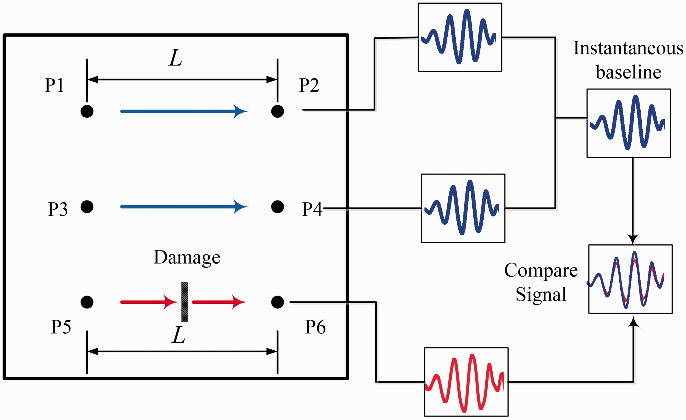
However, according to the basic scenario of IBM, pitch-catch pairs of different path lengths should not be compared to obtain the instantaneous baseline. To design a transducer network for damage detection using IBM, the location of the PZT disks should be seriously considered before data acquisition. Because of the restriction of uniform actuator-sensor pair length, larger number of PZT transducers or more complex transducer network will be necessary. Therefore, more flexible method is required without consideration during the distribution of the identical path length pairs in deeper study and wider practical application.
Based on the concept of IBM, a novel baseline-free damage identification method is proposed, which can extract a baseline signal from actuator-sensor pairs of different lengths. As shown in Figure 2, the distances of the three transducer pairs attached on the plate surface are modified to
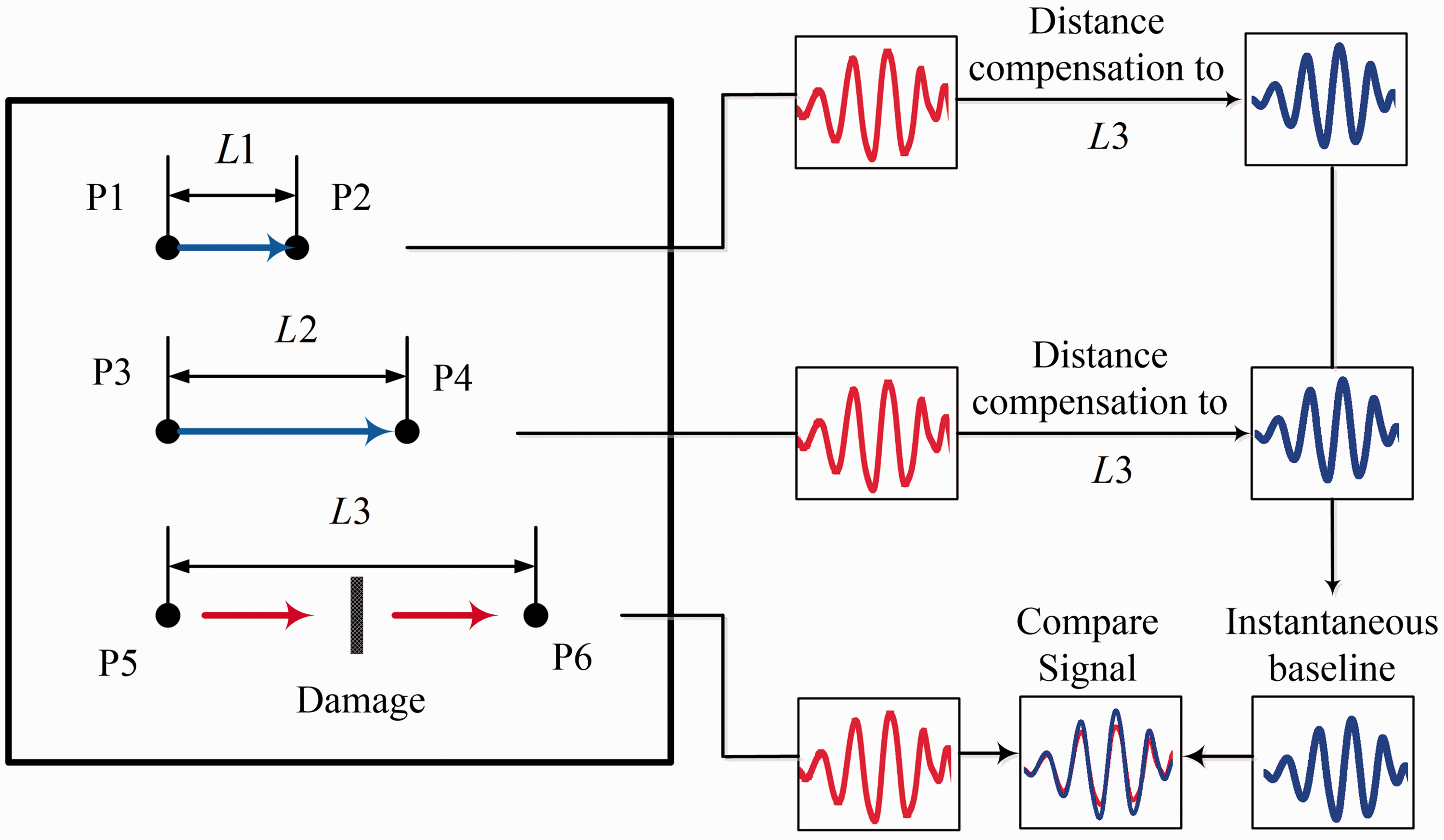
Baseline extraction from pitch-catch pairs of different length.
Before comparing all the waveforms of different path lengths directly, one more critical step is necessary. When signal of
The new baseline-free method can reduce the PZT number.
Distance compensation and damage identification
Consider a GW transducer adjusted on a one-dimensional structure. A field quantity in structure
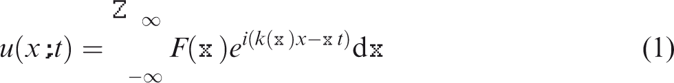
Equation (1) describes the wave propagation only in one-dimensional structure such as the bar or beam. When GWs propagate in plate-like structures, the energy is emitted in a circular-shaped way. Sensors of identical distance from the actuator will receive the signals of the same amplitude. Therefore, equation (1) can be expressed as

Schematic of wave prediction based on distance compensation using collected signal.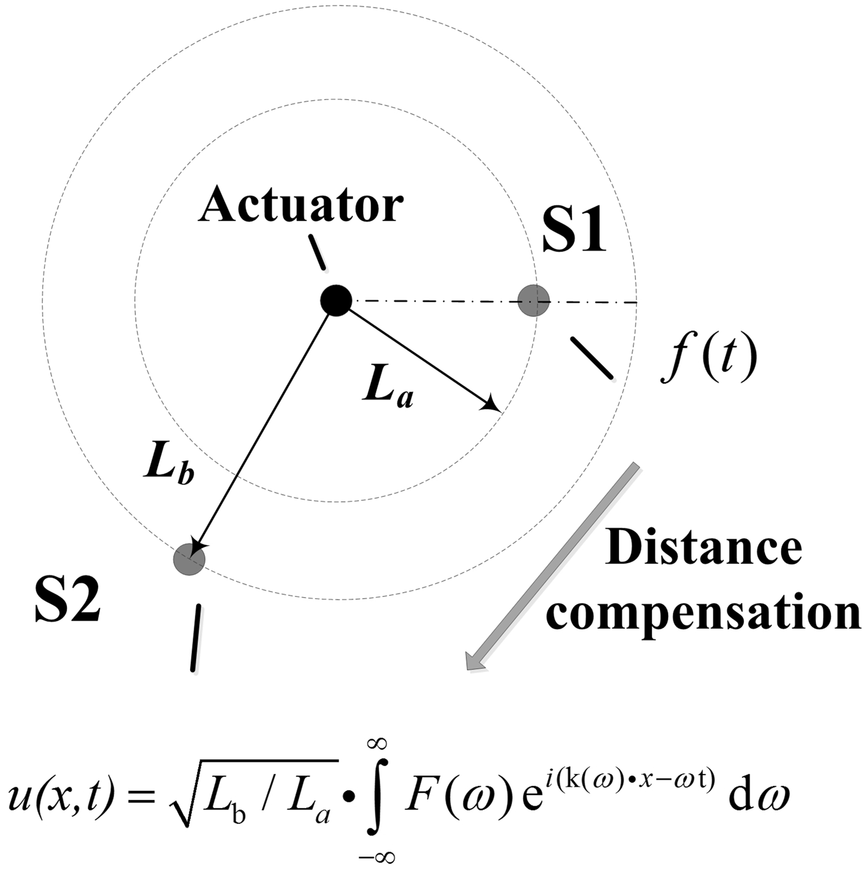
When the damage in the plate is a fatigue crack, the generated nonlinear wave is another damage feature to identify the damage. Variation iteration method 24 is an effective approach to solve the nonlinear wave equation. In this paper, we use the traditional numerical method to solve the Rayleigh-Lamb wave equation.
Practically, due to boundary reflection, the first arriving wave is most commonly used in mode recognition during signal interpretation. Therefore, wave prediction and subsequent baseline extraction only focus on the first arriving wave packages, which are referred to S0 modes. That means the

For a 3-mm-thick 6061 aluminum plate, the wavenumber for symmetric modes is plotted in Figure 5. We can predict the wave propagation of a certain mode. Note that in this calculation of equation (2), the integration over the negative frequency range is equal to that over the positive frequency range, and the compensated signal in this study can only be obtained from the positive part of the integration.
Wavenumber plot for 3-mm-thick aluminum plate.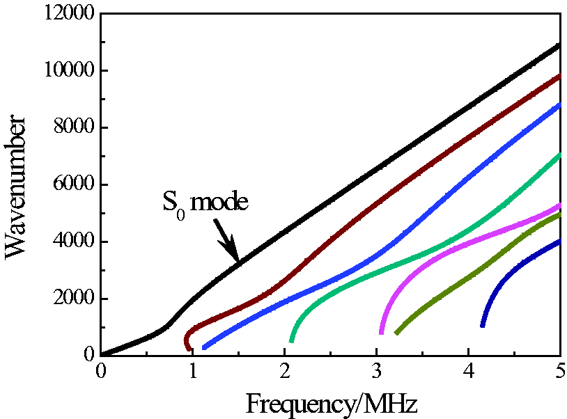
It should be observed that the proposed method abstracts an instantaneous reference from the signals along different directions in the presented structure, which is infeasible in anisotropic materials. Therefore, this work aims to develop a baseline-free method for the inspection of isotropic materials.
Simulations and experiments
Simulation in intact plate and experimental validation
To validate the proposed compensation method and discover the relative applications in damage detection in plate-like structures, a series of simulations and experiments have been conducted. Firstly, a finite element model of 900 × 900 × 3 mm (length × width × thickness) aluminum plate is generated in Abaqus/explicit. The schematic diagram is shown in Figure 6. An actuator disk (denoted as A) of 8-mm-diameter is fixed in the center of the plate, and three monitoring points marked as P1, P2 and P3 are located along horizontal direction (i.e. U1 in Figure 6). The distances between the actuator and sensors are 200 mm, 250 mm and 300 mm, respectively. Another monitoring point marked as P4 is located on the left side of the actuator. A notch of 20-mm-length and 2-mm-width is introduced in the path of A-P4 pair to validate the efficiency of the damage detection based on distance compensation algorithm.
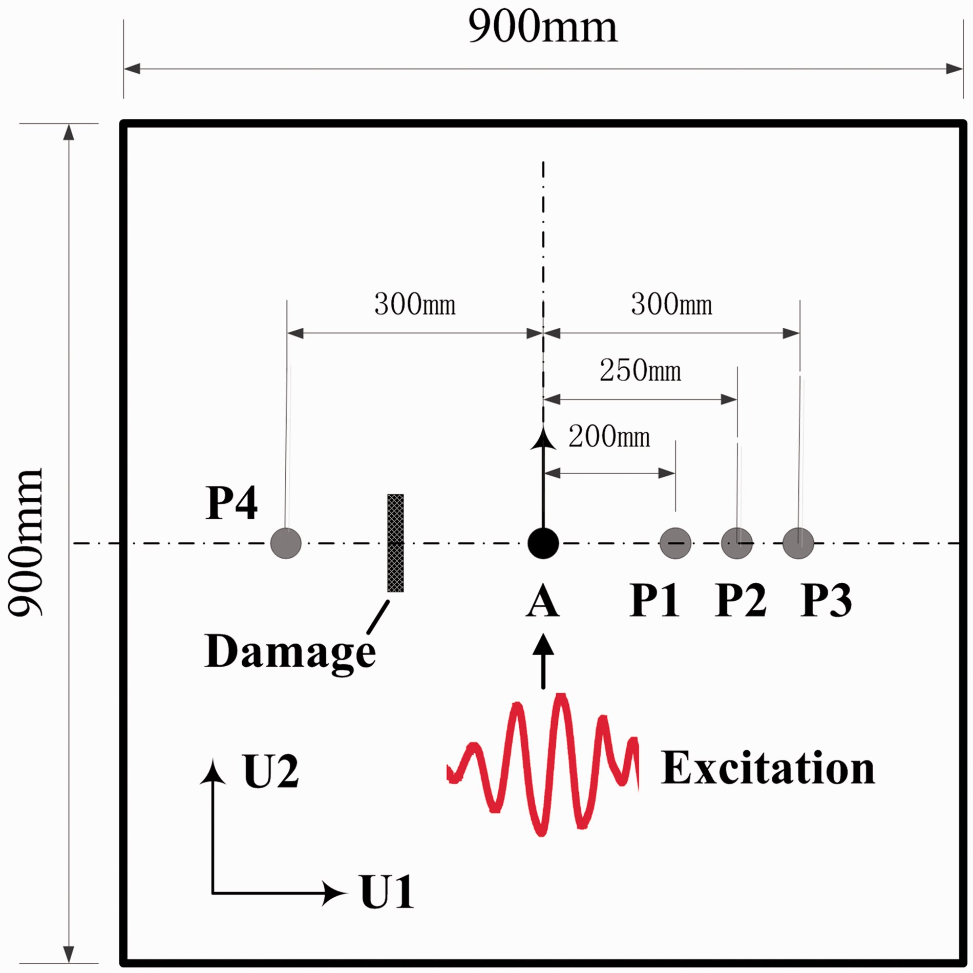
Schematic of the transducer setup in simulations.
A 5-cycle Hanning-windowed sinusoidal toneburst at the central frequency of 150 kHz is selected to generate Lamb waves. The Young’s Module, Possion ratio and density of the plate are 7 × 10¹⁰ Pa, 0.3 and 2700 kg/m3, respectively. To ensure the accuracy of the simulation, the element size is kept 2 mm to meet the requirement that a wavelength should contain at least seven elements. The U1-displacement response of the three points is extracted and plotted in Figure 7.
Figure 7 shows the wave propagation along U1-direction. The amplitude of S0 mode decreases due to the longer travelling distance. In addition to the amplitude variation, the duration of S0 mode in the three signals is also different from each other because of the dispersion effect. To compensate the signals of P1, P2 and P3 to 300 mm propagating distance, the algorithm based on equation (2) is used to process the data. The first arriving wave packet is referred to S0 mode, the comparison of the compensated signals is shown in Figure 8. P1* and P2* denote the compensated signals from P1 and P2 to the length of P3, respectively. The result shows that the three processed signals completely match with the both phase and amplitude of S0 mode. It means that signals from transducer pairs of different length have the potential to reveal health condition. It is noteworthy that the distance compensation processing only uses the propagation characteristic of S0 mode, hence the overlapped part of the three compensated signals contains only one wave package. The difference between the damage signal received by P4 and the compensated signal from P1 is shown in Figure 9. Significant amplitude difference between the two signals illustrates the feasibility of the proposed method in damage detection.
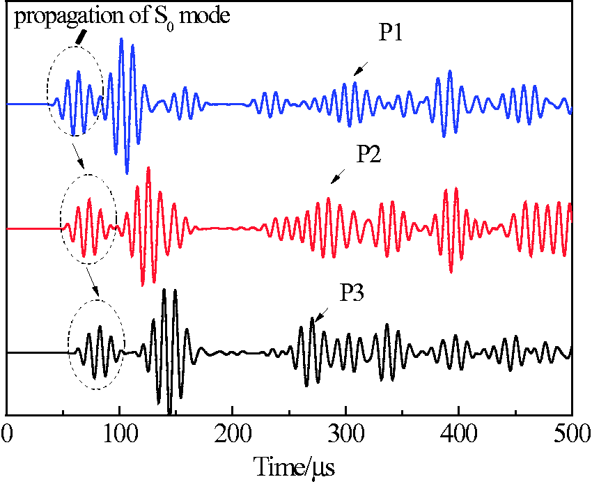
Wave propagation revealed by P1, P2 and P3.
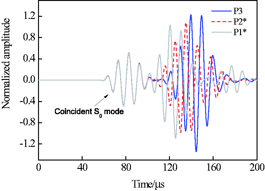
Signals comparison after compensation processing.
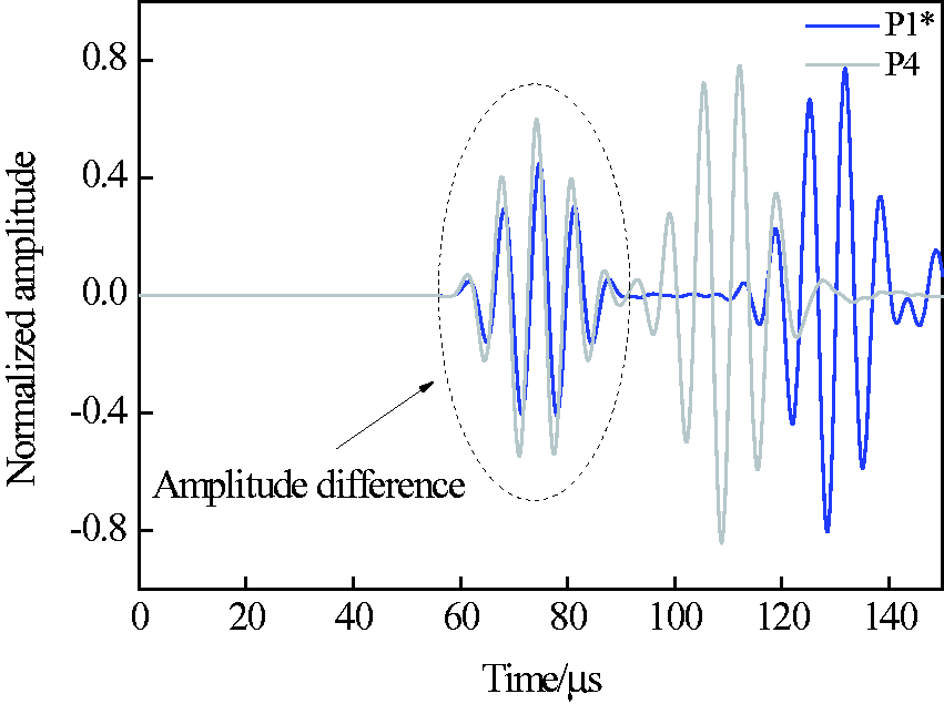
Amplitude difference of S0 mode between P4 and compensated P1.
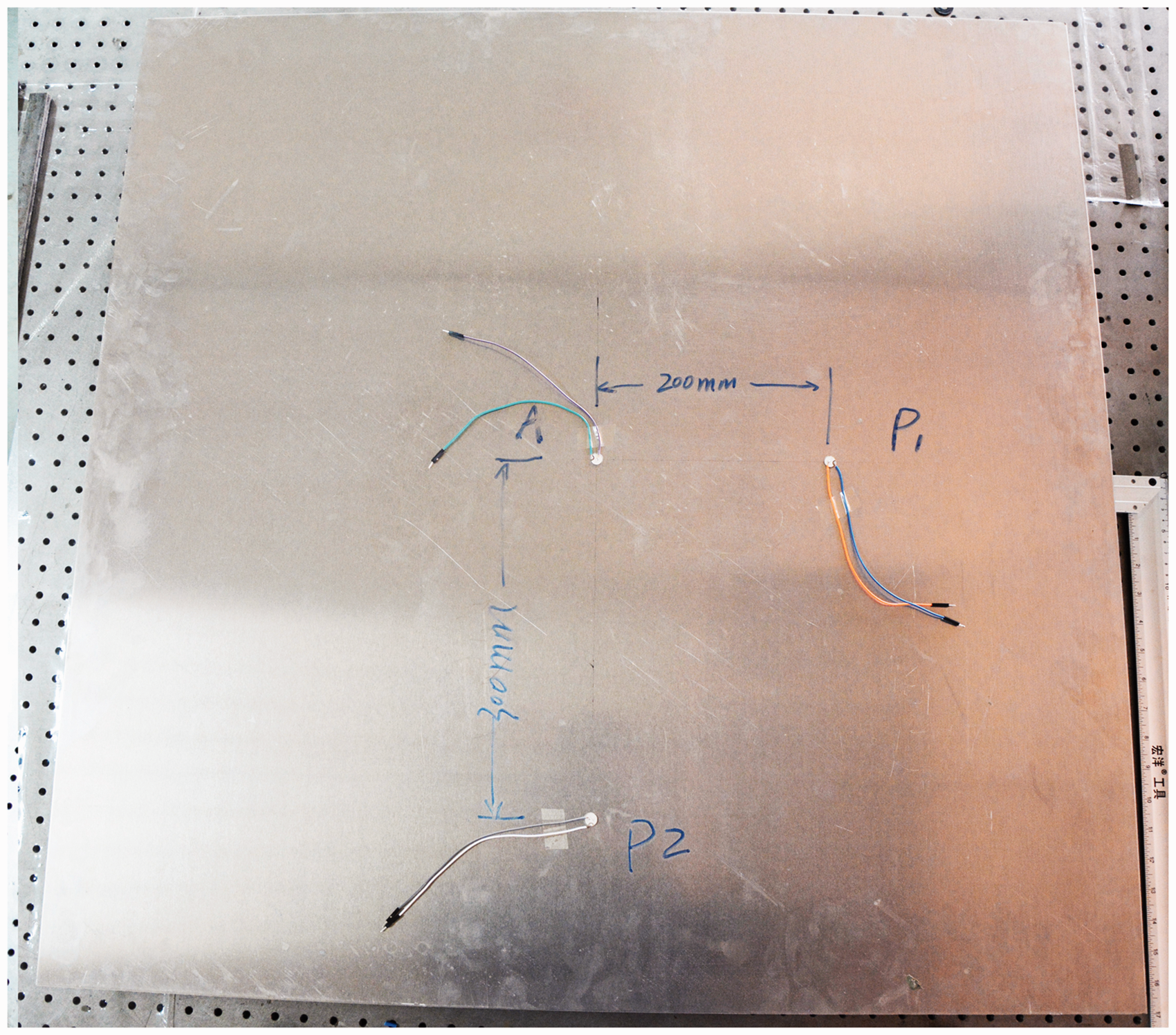
Moreover, a validation experiment is also conducted to demonstrate the efficiency of the distance compensate approach. Experiment setup is shown in Figure 10. A PZT disk of 10 mm diameter and 1-mm thickness acted as the actuator is placed in the center of an aluminum plate of 900 × 900 × 3 mm. Two sensors marked as P1 and P2 of identical size with the actuator are mounted at different positions, keeping the distance from the actuator 200 mm and 300 mm, respectively.
Validation experiment setup of compensation algorithm.
It should be observed that, before our adhesion, the bonding area should be carefully polished and cleaned. During the adhesion, the bond layer can significantly affect measurement. It is suggested to choose the adhesives of high shear modulus and the smallest practicable bond-thickness in order to minimize the influence of the bond layer.
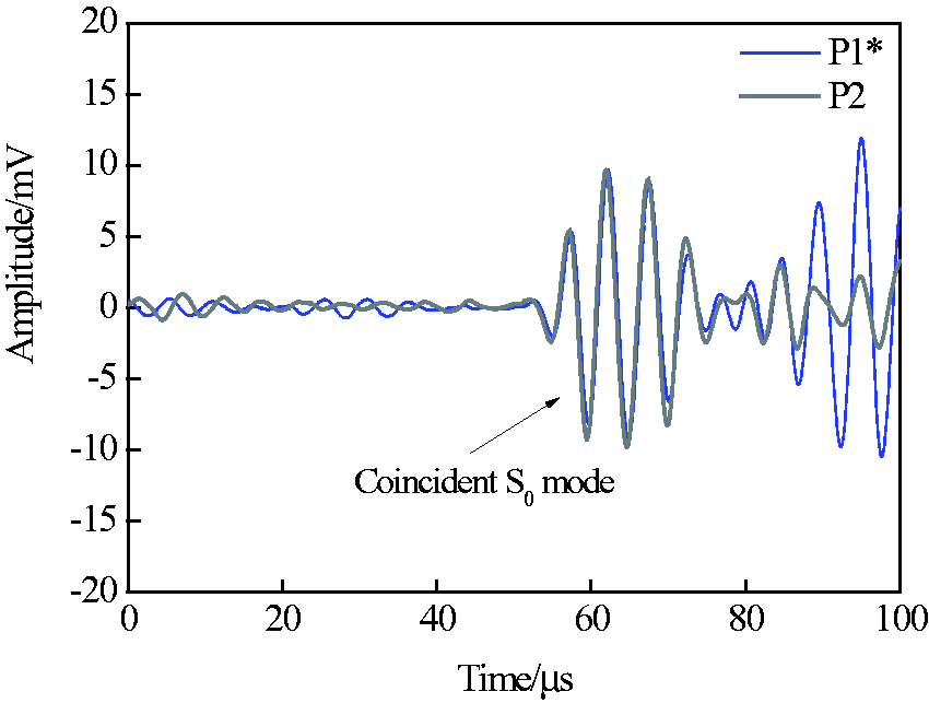
A Hanning window tone burst excitation centered at 150 kHz is amplified to generate Lamb wave. Signals received by P1 and P2 are plotted in Figure 11. Due to shorter travelling distance, S0 mode received by P2 lags behind P1. Using the compensation algorithm, signal of P1 is acting as an excitation signal and travelling for another 100-mm distance, corresponding signal is compared with P2 shown in Figure 12. P1* refers to the compensated signal collected at P1.
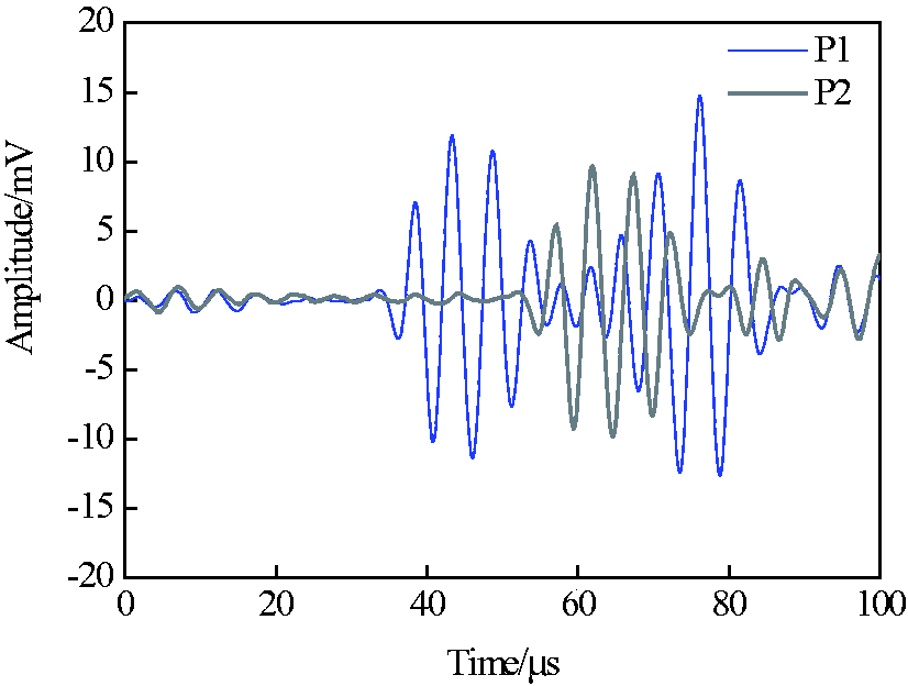
Signals received by P1 (200 mm from the actuator) and P2 (3000 mm from the actuator).
Basically, compensation results of the experimental data match with the simulation results. However, some minor differences exist at the arrival of S0 wave. In the simulation, we can control the wave propagation under an ideal environment; while in practical proceedings, there may be a little difference. Moreover, there is a little noise before the direct arrival of S0 wave in both sensors due to the electric disturbance. In summary, the result shows a good agreement on the first arrival of waves of the two signals, illustrating that the compensation algorithm is efficient to unify the signals from different transducer pairs.
Distance compensation when excitation frequency in dispersion zone
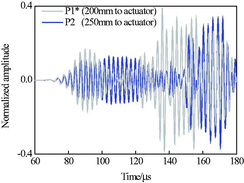
In section Simulation in intact plate and experimental validation, the simulations and experiment are conducted at the central excitation frequency of 150 kHz, where the dispersive effect is not severe. The results validate that the compensation algorithm is efficient for signal prediction and damage identification. To achieve high sensitivity of damage feature, excitation frequency should be kept higher to adapt to the micro flaws. When the excitation frequency of 400 kHz is selected to generate Lamb waves in intact aluminum plate shown in Figure 6, signals of P1, P2 and P3 are received and analyzed. Excitation of 400 kHz can cause high dispersion effect and results in a significant gap between phase velocity and group velocity. Signal of P1 is compensated to the travelling length of P2 and P3, respectively. From the comparison shown in Figures 13 and 14, we can observe that the compensated signals do not match with the targeted waveforms, which are received from the real positions. Moreover, with the increase of the propagation distance, the difference between the prediction and target is becoming more obvious. This error is caused by the inaccuracy of the
Comparison between the received signal by P2 and the compensated signal of P1.
Signals comparison between compensated P1 and P2 under 400 kHz excitation.
Generally, dispersive range depends on the product of frequency and sample thickness. In the current scenario, excitation frequency of 1200 kHz mm belongs to severe dispersive range. Similarly, in other samples with different thickness, the dispersive frequency can be calculated according to the product of frequency and sample thickness. Therefore, it is demonstrated that the selection of excitation frequency is important in this work. When samples of significant thickness are inspected, relatively lower excitation frequency is recommended for the compensation precision consideration. In summary, the excitation frequency should be carefully selected according to the dispersion curves.
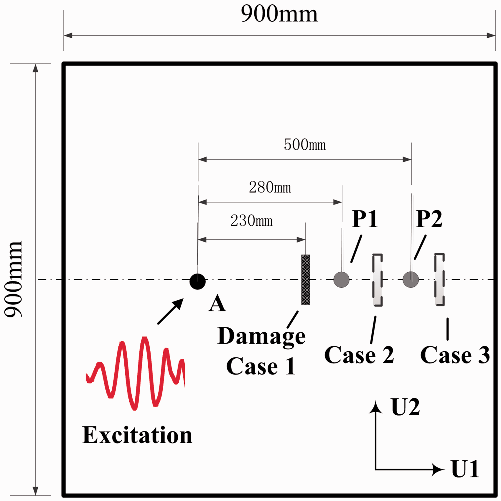
Distance compensation for signals in damaged path
Distance compensation for signals in undamaged path is discussed in previous subsection, and the efficiency is demonstrated by both simulation and experiment. However, signal propagation prediction may lose its precision when GW encounters damages in the travelling path because the energy reflection causes amplitude loss. Current subsection includes damage detection using distance compensation when the wave travelling path is damaged, and it has been illustrated in Figure 15. Voltage of 150 kHz excitation is acted on the actuator denoted as A to generate Lamb waves in a 3-mm-thick plate. Simulations are conducted to investigate the received signals by P1 and P2 under three damage location cases, respectively. Case 1 refers to the damage location between the actuator and P1, case 2 refers to the damage location between the two sensors and case 3 refers to the damage location at the most right side of plate. Notch length and width in all three cases are 20 mm and 2 mm, respectively. Three signals received by P1 are compensated to the distance of P2 and compared in Figure 16. In case 1, it is found that the amplitude of P1 is smaller than that of P2. This phenomenon is caused by diffraction effect of GW. Sensors closer to the damage have greater difference from the instantaneous baseline. In case 2, amplitude of P2 is smaller than P1 due to the existence of the notch. In case 3, when the distance between the damage and the sensor is larger than a certain value, there would be no any amplitude difference, because P1 and P2 both received the direct S0 wave. Here, the distance between P2 and the damage is set to be only 30 mm. The direct S0 wave in the signal captured by P2 is interfered by the echo, and the amplitude is also little smaller than that in the intact structure. However, it is noticed that the amplitude difference is much smaller than that in case 2. The results demonstrate that the compensation algorithm is capable to maintain the damage information.
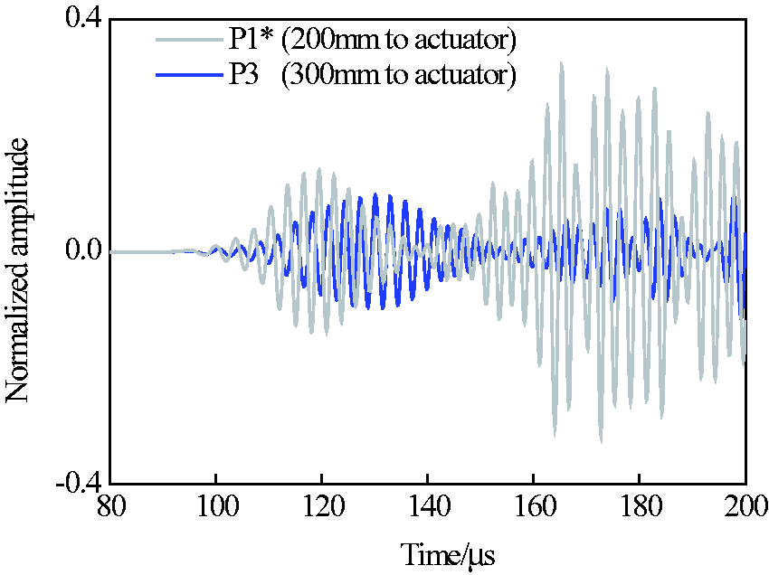
Signals comparison between compensated P1 and P3 under 400 kHz excitation.
Algorithm validation under three different damage cases.
Effect of damage size and classification on wave amplitude
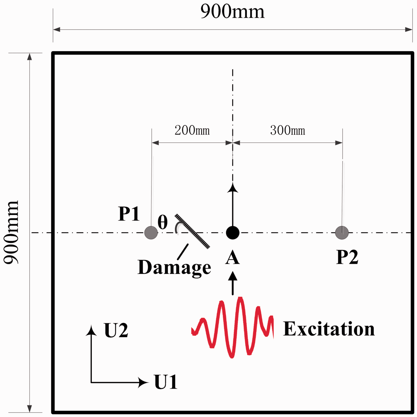
Damage in pitch-catch path can cause the difference between the amplitude of instantaneous baseline and interrogated signal. The length of the crack is not only the factor that influences the measurement results but the crack angle has also a significant effect. In practice, the angle of growing crack is totally unpredictable, so more reliable damage detection method should be developed. As shown in Figure 17, an artificial notch of the angle
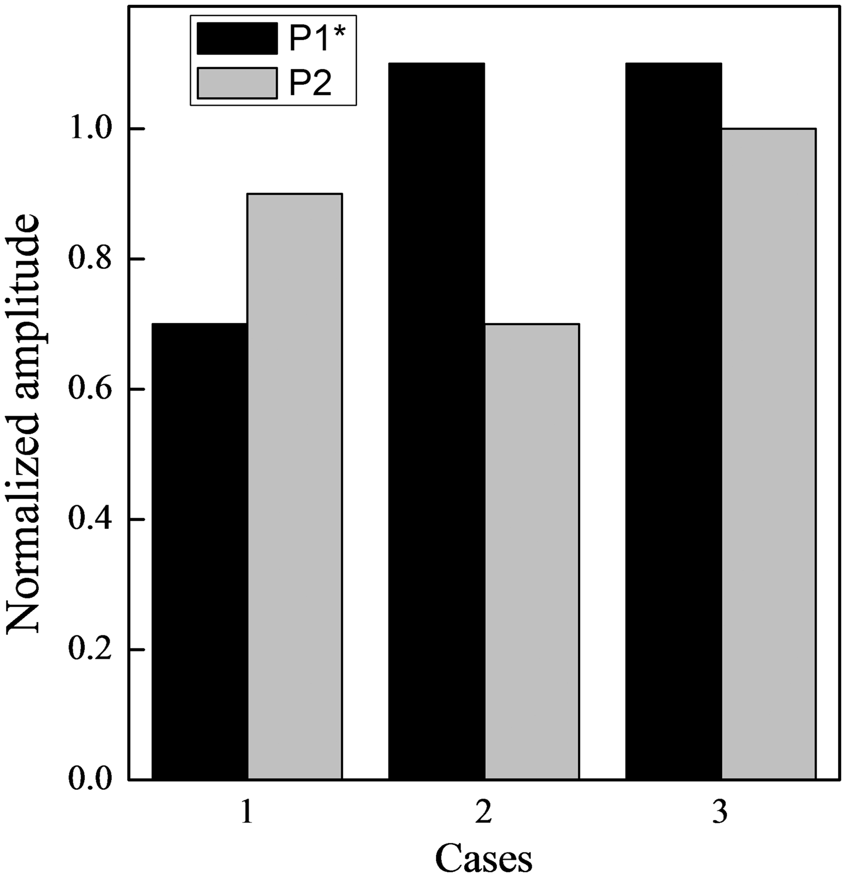
Amplitude of S0 mode of two sensors under three different damage cases.
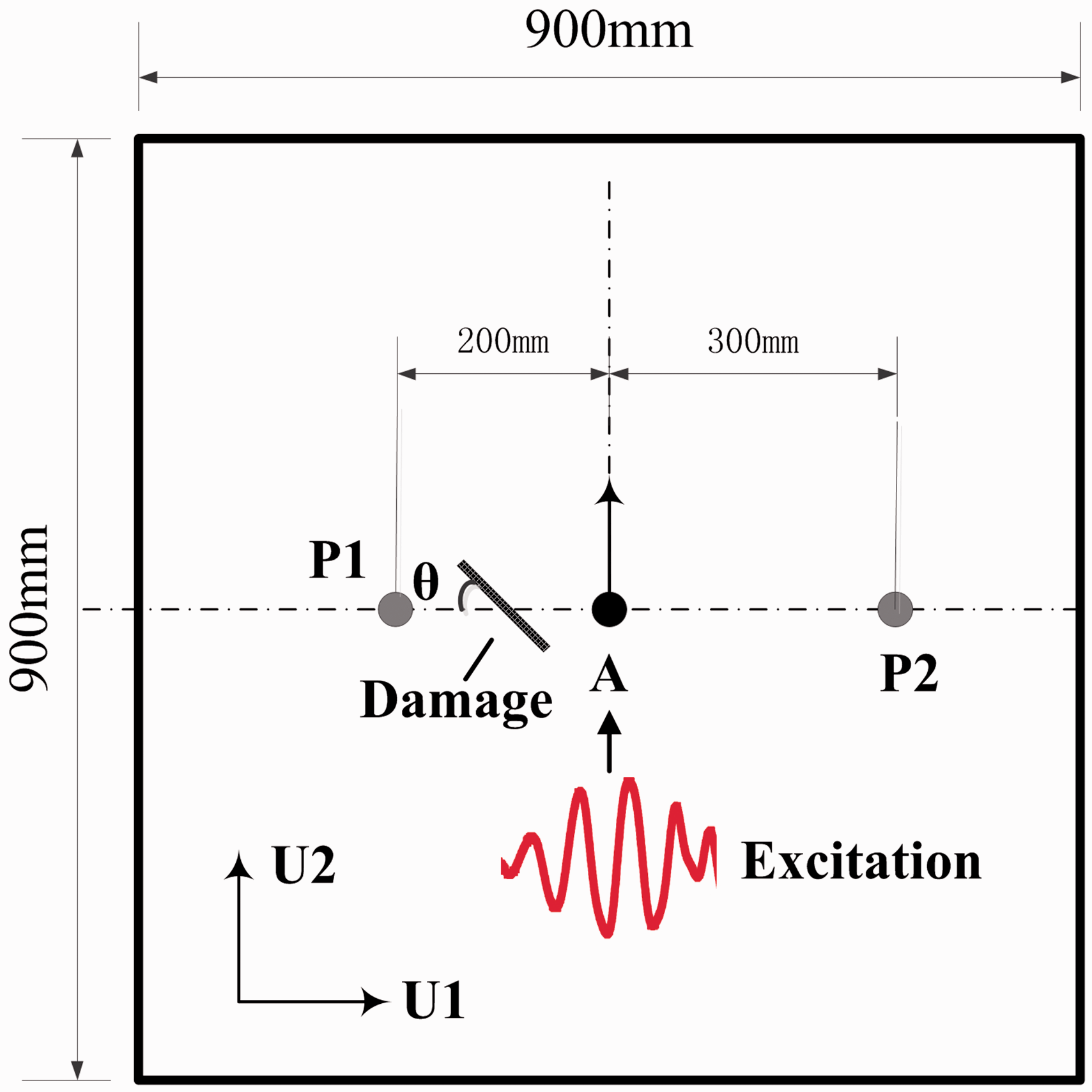
Notch with different angles to the wave travelling path.
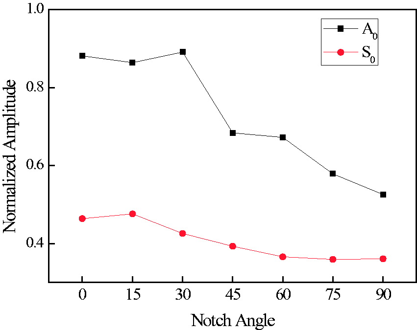
Amplitude variations of compensated S0 and A0 mode of sensor P1 due to notch of different angle.
Furthermore, increment in amplitude variation in S0 and A0 mode due to damage length is elaborated in Figure 19. It is found that increasing damage length has similar influence as that of angle variation. In fact, the projected length of the damage in the direction vertical to that of wave propagation is the main factor that affects the wave amplitude.
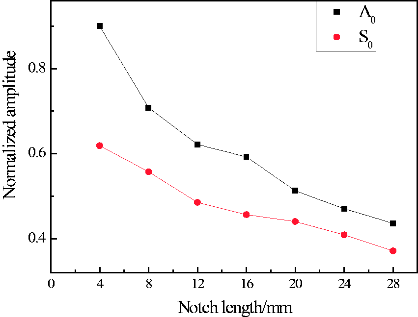
Amplitude variations of compensated S0 and A0 mode of sensor S1 due to notch of different length.
Simulations are also performed to investigate the influence of holes of different sizes on the damage identification. Schematics are shown in Figure 20. Similar to Figure 17, the hole is located at the position of 50 mm from the sensor P1. Same frequency is acted on the actuator to generate the Lamb waves in the plate. The diameters are changed from 4 mm to 28 mm. The data collected from P1 is compensated to the length of A-P2. The amplitudes of the two modes are plotted in Figure 21, showing corresponding trend of the amplitude variation.
Schematic of hole identification in the testing plate.
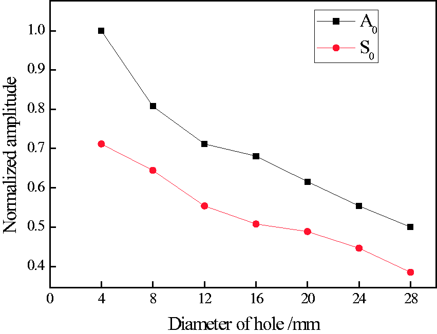
Amplitude variations caused by holes of different diameters.
Here, we obtained the same trend of the amplitude variation for the two different types of damage. The simulation results under a hole and a notch are compared. It is observed that there is no difference in signals between notch and hole if the notch length is equal to the diameter of the hole. The main factor accounted for this phenomenon is that the damage width within certain limit along the wave transmission direction is not critical to the signal changes under the pitch-catch configuration, because Lamb wave is sensitive to the damage vertical to the wave propagation, not in same direction. These remarks are similar to the fact that longitudinal modes in pipe structure are sensitive to circumferential damages, not to the axial material loss.
Damage imaging based on distance compensation
Damage diagnostic imaging algorithm
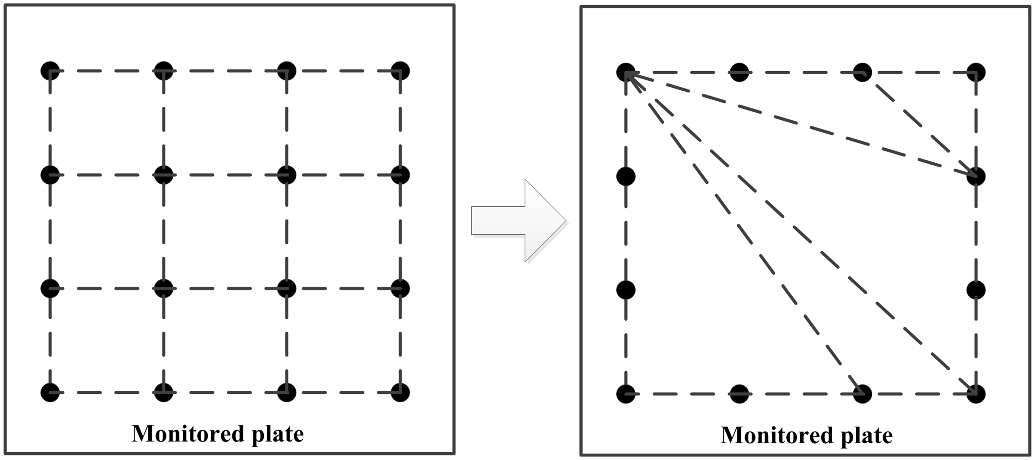
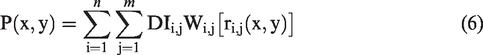
Probability imaging technique known as RAPID (reconstruction algorithm for probabilistic inspection of damage) is widely used in damage location of plate-like structures. For a 600 × 600-mm plate, 12 PZT transducers enclose the monitoring area of 450 × 450 mm size as shown in Figure 22. The distance between two adjacent PZTs on whole surface is 150 mm. Several damage features and eighty-four paths will be extracted and measured from the results. Damage index (DI) of the nth path is defined in this study as

The plate is meshed into uniform 2 × 2-mm grid. Assuming that there are
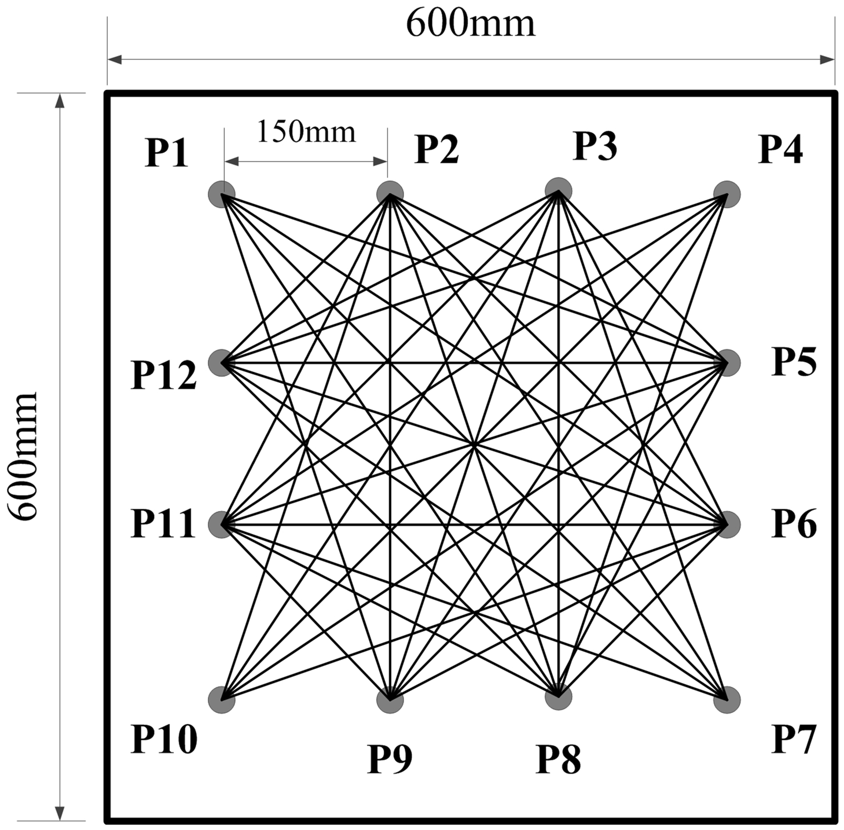
Selected sensing paths in the monitoring area enclosed by 12 transducers of 600 × 600-mm plate.
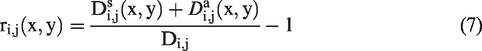
In this equation,
In this study, the probabilistic weight is given by
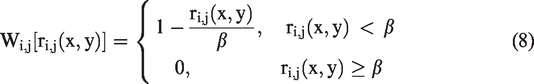
The coefficient
Transducer network setup and experimental results
As mentioned in previous section, this baseline-free damage detection technique can overcome the restriction of the difference of distances between actuators and sensors. In this section, a validation experiment of RAPID using proposed distance compensation approach is conducted to evaluate its potential in practical application. Figure 23 demonstrates the corresponding experimental setup. In this validation section, we adopted the transducer network of most commonly used shape as in other damage imaging techniques. In other words, the pattern of the network can be adjusted according to the shape of the examined plates. After completing the bonding of each PZT transducer, the imaginary part of electrical admittance is measured under each excitation frequency, using the circuit described in the work of Park et al. 26 In this way, each PZT is calibrated and have identical performance. Moreover, the pairs are tested in a sequence; start from P1-P2, P2-P3, P3-P4 to the last pair P11-P12. During the measurement of the responses under the same excitation frequency, transducers which have different response would be removed. In that case, we can verify the performance of the PZT transducers one by one.
The position of transducer P10 is defined as the origin coordinates (0, 0). In the first step, an artificial damage of Φ2 mm hole is introduced at the coordinate of (400, 225) as shown in Figure 23. A sinusoid tone-burst of five number of cycles at central frequency of 150 kHz, modulated by a Hanning windowed is generated and amplified by the peak-to peak voltage of 20 V, has been applied to each PZT disk of the sensor network. Signals of 84 paths shown in Figure 22 are received and compensated to two distances of P1-P5 and P1-P7, respectively. Distance of P1-P7 is the longest among all paths and P1-P5 is nearly the average distance. Coefficient β is selected as 0.05 in the imaging algorithm, and the imaging results are shown in Figure 24. Even though the position of maximum probability is coincident with the real hole, the results are not precise because of existence of many other relatively large probability areas. The location error may come from the following two sources: (1) Φ2 mm hole cannot induce the sufficient amplitude difference, (2) compensated amplitudes of transducer pairs could not match perfectly because the calibration of the transducer cannot be controlled in an ideal standard. Moreover, the amplitude difference induced byΦ2 mm hole is not enough to cover the minor difference among the transducer pair, and damage is identified in or near the path but cannot be located at a specified point for each pair. From the location imaging, Φ2 mm-hole is hardly to be detected by this method.
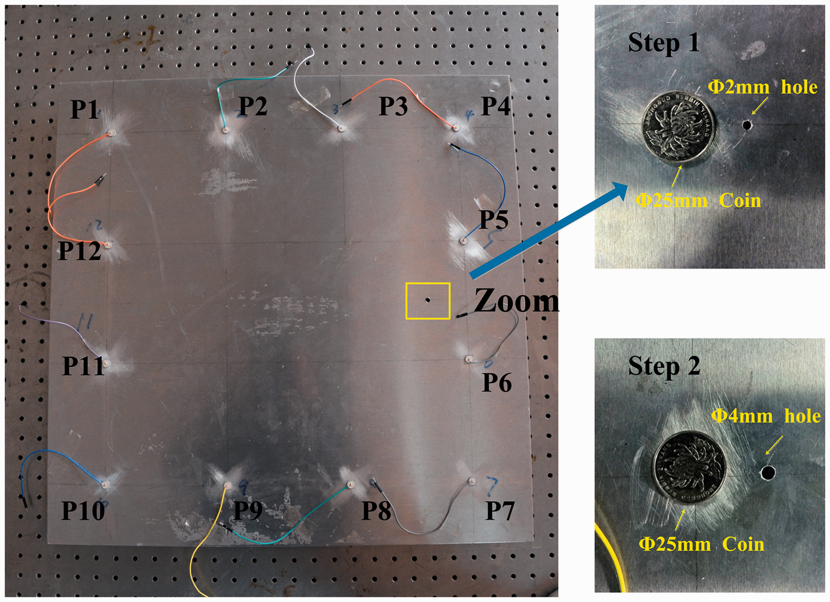
The monitored aluminum plate with introduced hole and the transducer network on the surface.
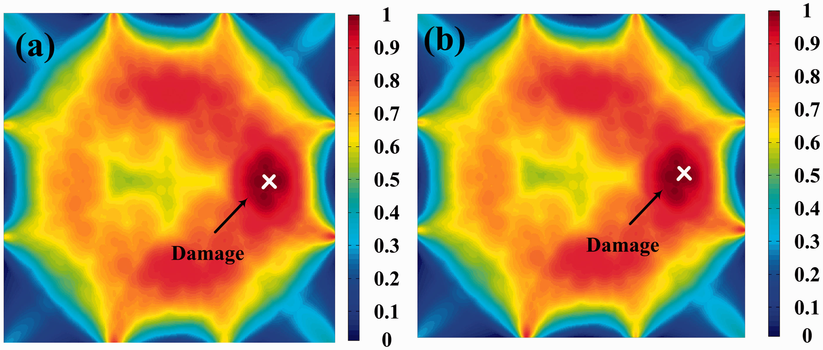
Damage imaging forΦ2 mm hole based on compensation algorithm when compensation distances are (a) P1-P5 length and (b) P1-P7 length.
In the second step, Φ4 mm-hole is introduced at the same position; and the corresponding imaging results are shown in Figure 25. Because the information of amplitude loss caused by damage will not be eliminated during the compensation processing, both imaging results are perfectly matched with the damage position.
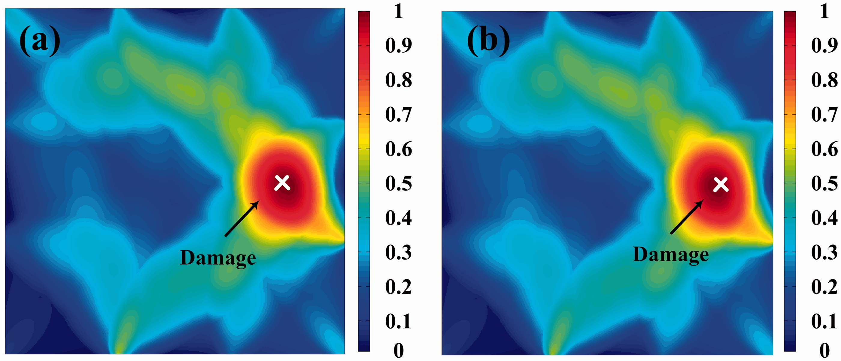
Damage imaging for Φ4-mm hole based on compensation algorithm when compensation distances are (a) P1-P5 length and (b) P1-P7 length.
Moreover, measurements and compensations are conducted when the environmental temperature is changed, and the imaging result also agrees with the real position of the damage. Because all the pitch-catch pairs are subjected to identical temperature changes, so the differences between the wave signals are only related to the structural damages. It is demonstrated that the proposed baseline-free method performs efficiently in practical application.
Discussion and conclusions
Conventional SHM techniques based on GWs excessively rely on the baseline signals collected from pristine structures. However, the baseline data are difficult to be obtained under varying environmental conditions. To guarantee the precision of damage identification, developing baseline-free damage detection methods is significant in practical structural monitoring work. Conventional IBM builds identical wave travel paths to extract a baseline in current environment; however, this approach needs a large number of PZT transducers. In this paper, a novel damage identification method for plate-like structures based on distance compensation is proposed to overcome this shortage.
A new baseline-free damage-detection technique is proposed based on distance compensation for pitch-catch pairs of different length. This approach can overcome the drawbacks of IBM which have no capability of processing pitch-catch pair of different length. Moreover, it can be inferred that the proposed method is suitable for the inspected plate of non-symmetrical shape, which is a significant improvement over traditional IBM method. Using the propagation characteristics of a certain Lamb wave mode, signals received by a transducer pair of shorter length can be predicted to a longer wave travelling distance. Thus, a baseline in a totally new environment can be extracted if the data are fused to reveal the damaged paths. Both simulations and experiments are conducted to validate the efficiency of the proposed method. Finally, a damage imaging technique based on amplitude loss ratio is developed. The imaging approach is proved to be feasible through an experimental verification.
However, this method also has some shortages in practical applications. Firstly, before the distance compensation, the material properties in the calculation of relatively precise dispersive curves should be obtained. Thus, there is one more step in the inspection for the measurement of the material. Secondly, the compensation precision is affected by the wave propagation distance. Therefore, the inspection size is limited. The transducers should be arranged at the locations where damage easily occurs.
Footnotes
Declaration of conflicting interests
The author(s) declared no potential conflicts of interest with respect to the research, authorship, and/or publication of this article.
Funding
The author(s) disclosed receipt of the following financial support for the research, authorship, and/or publication of this article: The National Natural Science Foundation of China (NSFC No. 11372179), Innovation Project of Shanghai (No. 15JC1402600), and the National Science and Technology Major Project (No. 2017ZX04011014).