
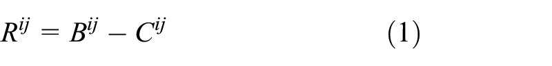
Abstract
In this article, a method for addressing temperature effects using Lamb waves is developed with application to baseline comparison damage detection. The proposed method is based on baseline signal stretch with an improved minimum residual allowing correction over a larger temperature range. The effectiveness of the proposed approach in detecting (artificial) damages is demonstrated experimentally over a large temperature. The method is also shown to accurately detect and localise a crack in an aluminium panel and actual impact damage on a carbon fibre reinforced polymer panel.
Keywords
Introduction
Structural health monitoring (SHM) is an emerging branch of non-destructive testing (NDT), which can provide a real-time in situ alternative to classical NDT methods. As a real-time method, requiring little to no downtime after initial installation, SHM is particularly advantageous for the aerospace industry. The current schedule-driven maintenance regime can be streamlined when used in tandem with SHM systems, leading to a condition-based maintenance philosophy. SHM methods could potentially allow for adoption of lighter composite materials through early detection of barely visible impact damage (BVID) in carbon fibre reinforced polymer (CFRP) materials. The ultimate aim of active SHM for aerospace application would be to detect structural damage, characterise severity and location, in real time under operational environmental conditions.
Guided waves are of interest in SHM applications due to Lamb waves’ relative ease of activation and the ability to interrogate large areas with transducers. These waves can form when the wavelength is of the same order as the plate thickness. Guided wave SHM principally relies on ultrasonic wave propagation in plate-like mediums and by analysing diagnostic waves it is possible to interpret the health of a structure. Depending on the frequency of actuation and the thickness of the structure, many Lamb wave modes can be activated with velocity being dependant on both of these parameters. At low frequency × thickness values (less than 1 MHz mm), only a symmetric and a slower anti-symmetric mode are typically activated (fundamental or zero modes). At increased frequency thicknesses, higher order modes appear. The phase velocity of the zero modes converges to the Rayleigh velocity while other modes converge to the transverse velocity (Rose, 1999). The effects of temperature on Lamb waves are threefold: length dilation changing propagation distances, thickness dilation changing the frequency thickness product and changes in the material properties (e.g. Young’s modulus) varying the propagation velocity. It has been shown that the temperature effects are dominated by changes in material properties (Konstantinidis et al., 2006). Lead zirconate titanate (PZT) transducers provide an effective solution to both actuation and sensing by exploiting the direct and inverse piezoelectric effects.
A popular SHM approach (Michaels and Michaels, 2007; Sharif-Khodaei and Aliabadi, 2014) is based on comparison of a structure’s pristine state ultrasonic response (baseline) with the response at a later time (current). The baseline is subtracted from the current signal to leave a residual signal which may represent damage scattered signal. The baseline comparison methods have been shown to successfully deal with structural complexities (Michaels, 2008). Both the current and the baseline responses will include identical responses due to the complex features, so they will not appear in the residual signal. It has been shown by Michaels and Michaels (2007) that an active PZT configuration can be used with a baseline comparison routine to localise damage in thin plates. Various enhancements can be factored in to improve the detection accuracy, as explored by Flynn et al. (2011) and Sharif-Khodaei and Aliabadi (2014).
All baseline comparison strategies are adversely affected by environmental conditions (Wilcox et al., 2008), and it should be pointed out that all methods require some form of reference (Worden et al., 2007), even if not referred to as such. Temperature, loading condition, humidity and background noise, to name a few, are important environmental conditions. Currently established temperature correction methods compensate changes in velocity using baselines recorded at a range of temperature points: optimal baseline selection (OBS) and stretching the signal for fine adjustments between the recorded temperatures (baseline signal stretch (BSS)). These methods utilise baseline sets recorded at a temperature resolution defined by the capability of the BSS. Without this, it was found that these methods are not able to compensate for large temperature differences (Croxford et al., 2010; Le Duff et al., 2014; Lu and Michaels, 2005; Wilcox et al., 2008) or did not localise (Ambroziński et al., 2014). This is partly due to the distortion of the frequency content because of the large-scale stretching required for increased temperature change. The BSS method can be performed in the time or frequency domain, both with similar levels of performance (Croxford et al., 2010; Michaels, 2008). To improve damage detection predictions after applying BSS, Clarke and Cawley (2010) developed a method centring on changing the coverage area. The coverage area was varied by time gating the signal. Propagation time to limiting points was used as the time gate length with the limiting point on the very edge of the coverage area. A given coverage area has a specific artefacts and noise pattern while the actual damage location is left unchanged. Systematically changing the coverage areas based on evenly spaced limiting points yields damage maps with different artefacts and noise patterns. By fusing the damage image maps with different coverage areas, the effect of artefacts and noise is minimised while the actual damage prediction location is reinforced. Clarke and Cawley (2010) argue that this would improve the overall damage prediction and demonstrated it to be effective for a 5-mm diameter simulated damage.
Putkis and Croxford (2013) devised a continuous baseline growth strategy in which the required baselines would be acquired during the service life of the structure. If the maximum residual exceeds a threshold, it is determined to be caused by temperature and the signals are added to the baseline set. Cointegration methods for environmental trend compensation, drawing on the well-established methodologies developed in econometrics, have demonstrated success (Cross et al., 2011; Dao and Staszewski, 2013). The method combines cointegrated response variables to create a stationary residual which is representative of the undamaged state, any loss in stationarity will then be indicative of damage. The method can be used for damage detection and not localisation. This is because overall trends in the signal are established leading to a single value with an associated threshold for damage (Dao and Staszewski, 2013), or compensation of individual amplitude features (Cross et al., 2011), in both cases leading to loss in temporal information eliminating a route for locating damage. It was mentioned that for these methods that if environmental effects cause a significant enough change in the response, carefully selected baseline data sets are required (Cross et al., 2011). Other methods are also available requiring large baseline or training data set (Roy et al., 2014). Sohn (2011) proposed a reference-free crack detection method, in which a pure mode Lamb wave is excited by means of transducers placed above and below the plate. By assessing the various propagation paths, it was shown that mode conversion due damage can be identified.
To be able to exploit the inbuilt ability of baseline comparison methods for dealing with complex signals from structures, there is a need for improved temperature compensation strategies that do not require a large baseline set. The compensation method should preserve temporal information allowing damage to be located with a sparse array of transducers. Consequently, in this article, an improved BSS method is proposed.
The proposed improved modified baseline signal stretch (MBSS) is shown to be more effective than the existing BSS method over a larger temperature range. The new approach is validated experimentally and compared with the standard BSS approach, for detecting artificial damage as well as a crack in an aluminium plate and impact damage on a CFRP plate under varying temperature.
Methodology
Detection
Delay and sum algorithms have been shown to produce accurate predictions for damage location (Konstantinidis et al., 2007; Michaels, 2008). Extending the work by Michaels (2008), a delay and sum method that combines the damage probability map from all sensors, producing a fused probability image indicative of the damage location was developed by Sharif-Khodaei and Aliabadi (2014).
Key steps in the damage detection method adopted (Sharif-Khodaei and Aliabadi, 2014) is outlined in Figure 1 incorporating temperature compensation. In this method, initially the baseline
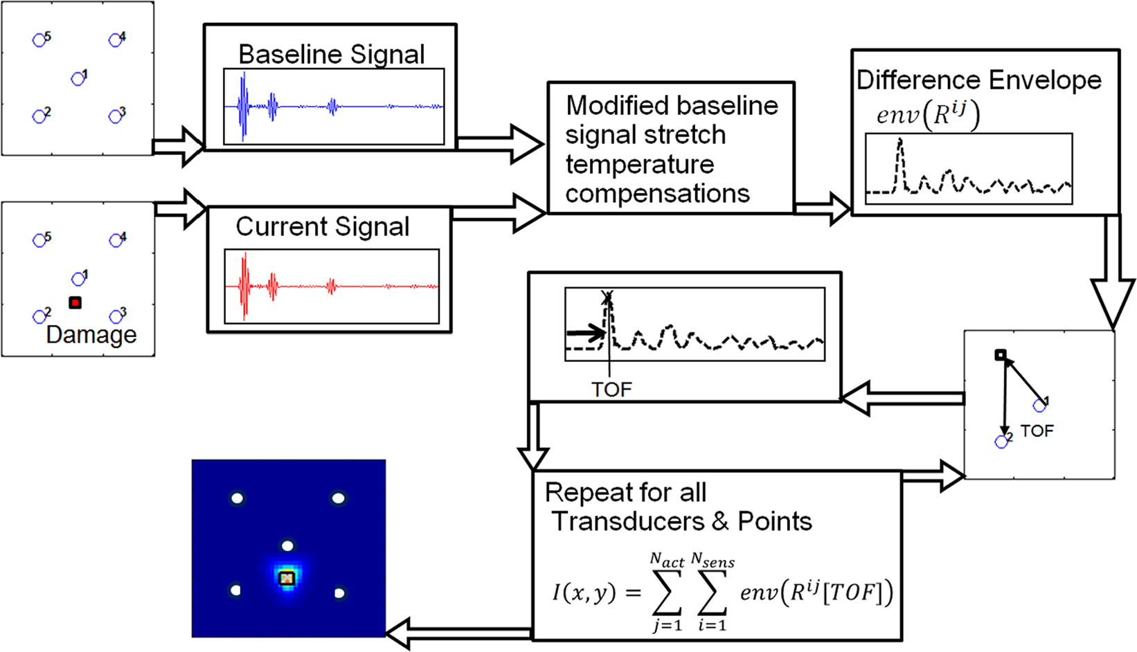
Key steps in the delay-and-sum damage detection method, producing a damage location predation map.
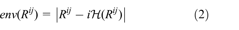
The envelope
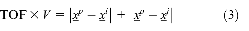
The group velocity is calculated using the time of arrival of the first wave packet and the corresponding sensor actuator distance. This is averaged for all transducers paths and a time of flight (TOF) offset incorporated to account for the experimental delays brought about by the hardware implementation. Having calculated the group velocity
The residual envelope
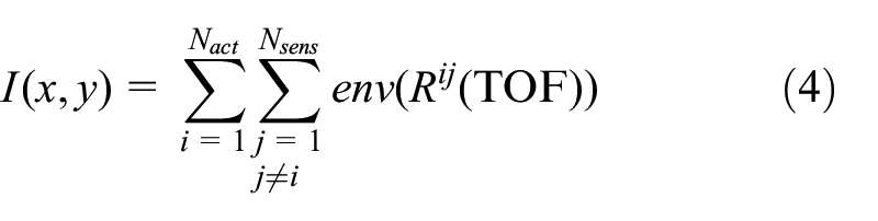
The stored values for each point are then summed to produce an image highlighting the predicted location of damage (Figure 1). It should be noted that the damage maps have a range of 0–1, normalised to the highest value.
MBSS method
The MBSS method presented in this article builds on the existing method (Lu and Michaels, 2005) for application to a larger range of temperatures, eliminating the need for a large baseline set.
The standard BSS method has been used with success (Croxford et al., 2010); however, a database of baselines at different temperatures is required or it will only be effective over relatively small temperature range govern the capability of the BSS method. For a practical implementation, a temperature step of 1°C–2°C is recommended on an isotropic plate (Croxford et al., 2010). Moll and Fritzen (2012) used a temperature step of 0.21°C to detect impact damage on a glass fibre reinforced plate. The limit on the temperature step in the baseline set is because first the stretching process results in slight distortions in the frequency content for large temperature changes. Temperature effects are more pronounced for higher order modes and differ between the fundamental modes (Dodson and Inman, 2013; Marzani and Salamone, 2012; Raghavan and Cesnik, 2008). Even if mode tuning is used in producing a single dominant fundamental mode, it may not be possible to exclusively excite only a single mode with conventional transducers attached to one side of a structure (Su and Ye, 2009). Presence of multiple modes brings about the need for multiple stretch factors for more effective temperature compensation over a larger temperature range. Additionally, the slight changes in arrival time of the wave packets lead to changes in the nature of the wave interference between successive wave packets.
A typical wave packet interaction is illustrated in Figure 2 with an exaggerated schematic of wave packets considering only the signal envelopes. It can be observed in the baseline signal that the overall envelope does not drop to zero in the region between packet one and two, this is in contrast to the current signal. This discrepancy is not as a result of damage but simply as a result of temperature change and will lead to deteriorations in detection accuracy. The lag in arrival of the combined signal can be corrected, the discrepancy in interaction of the wave packets, however, cannot be corrected if using a single stretch factor. More generally, the non-uniform change on wave packets may not be corrected by applying a uniform stretch factor, hence the need for a range of stretch factors as proposed.
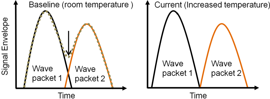
Exaggerated schematic highlighting wave packet interaction for temperature change. Arrow on the right indicates the location of packet interactions.
Instead of applying the same stretch factor to the entire signal effectively, a range of factors are applied and for each time point the minimum value for the residual envelope is retained.
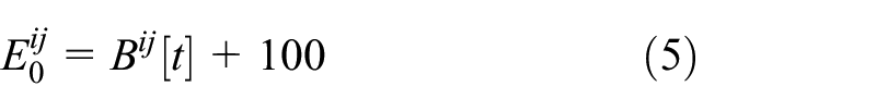
First, an arbitrary large residual envelope is defined by adding 100 (this value is assumed to be orders of magnitude larger than the original residual) to the baseline signal
Then, the actual residual is evaluated with stretch factor
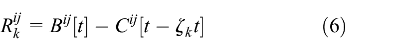
The residual envelope is updated such that
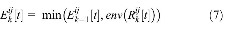
where
The proposed method is highly effective in compensating for the temperature and minimising the temperature residual envelope. The residual yielded is strictly less than that obtained from the standard method. The damage scatter is not removed by the modified method allowing for localisation of damage. This can be shown by applying compensation methods to damage signal obtained at the same temperature as the baseline signal for a simulated crack on an aluminium plate described in section ‘Aluminium plates’.
It can be observed that the maximum damage residual levels depicted in Figure 3 show little reduction over the different transducer paths, see Figure 7 for path definitions. For the damage in the direct path (e.g. path 2-5), there is almost no change in the compensated residual compared to the raw damage residual, both in terms of the maximum value and the overall residual envelope Figure 4(a).
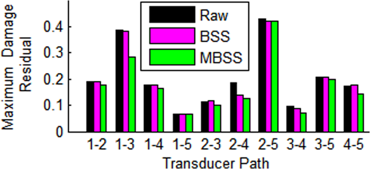
Maximum damage residual comparison after applying temperature compensation.
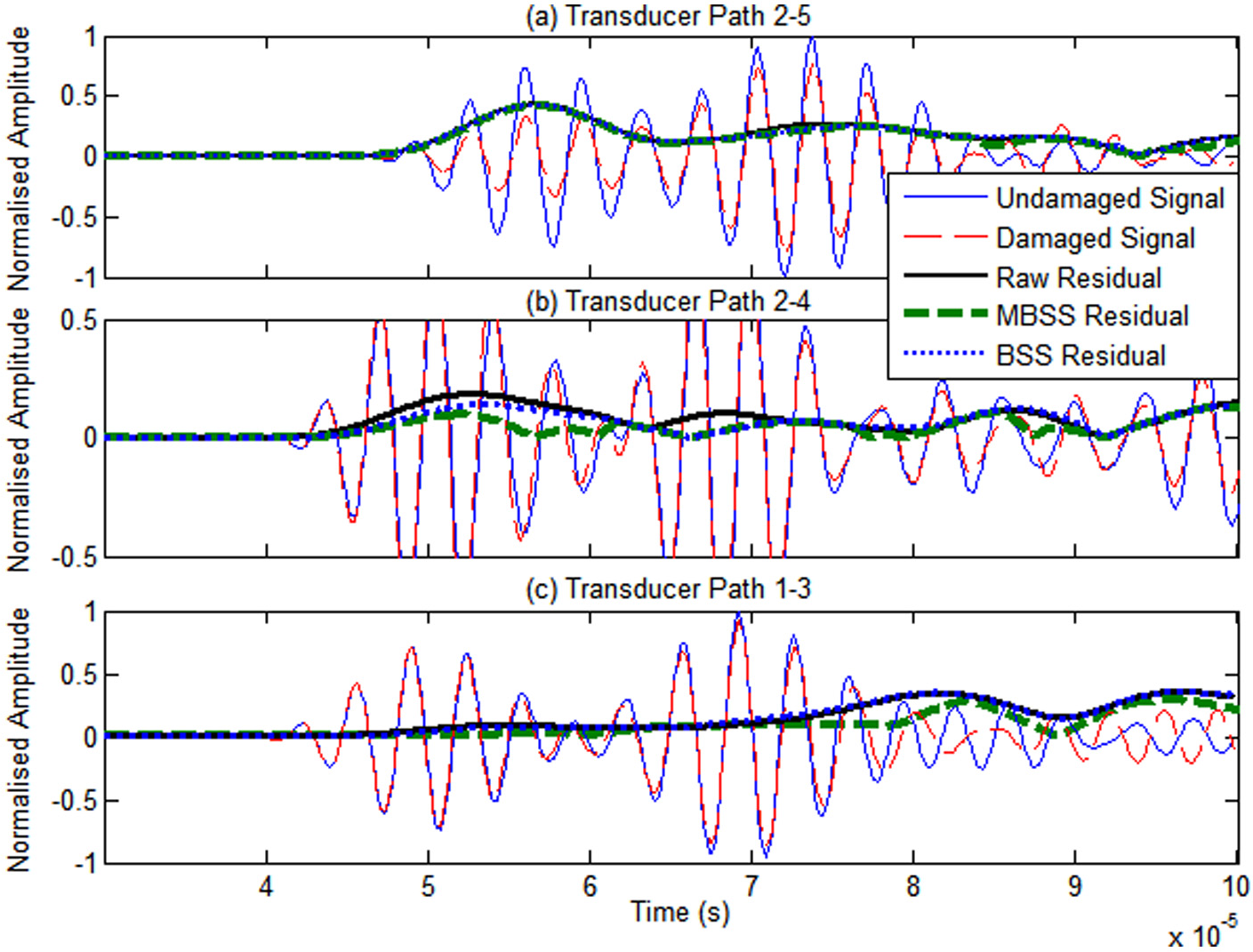
Damage residual after applying temperature compensation to damage signal recorded at the same temperature as the baseline signal: (a) damage in the direct path of transducers, (b) and (c) damage not in the direct path. 1.3 mm thick aluminium plate excited at 300 kHz.
It should be noted that the reduction in residual is most apparent for both the BSS and MBSS methods when the damage is not in the direct sensor actuator path, for example, path 2-4 or 1-3. This is because the damage causes phase shift in the sensor signal, this behaviour is highly dependent on the damage scatter and the distance to the transducers. The shift caused by damage will be reduced by signal stretching based methods as observed in Figure 4(b), for both the BSS and MBSS method. In all cases, the residual is always lowest for the MBSS method. It must be stressed that the modified method does not remove the residual signal due to damage, allowing accurate damage detection and localisation over a wider range of temperatures as compared to the normal BSS method. This is demonstrated by accurate localisation of damage shown in results section ‘Experimental results and discussion’.
Experimental procedure
Ultrasonic signals were excited in an aluminium and CFRP composite panels subjected to elevated temperatures using a network of attached transducers. Transducers were attached only on one side of the plate. In all cases, a five-cycle Hanning windowed tone burst actuation signals was generated with a National Instruments (NI) PXIe 5140 arbitrary signal generator with a built-in amplifier. The structural response was recorded as the sensor output voltage signal with an NI PXIe 5105 digitiser. For each sensor–actuator path, data were recorded 10 times, averaged and band-pass filtered with cut off at a third and three times the actuation frequency for the high- and low-pass limits, respectively.
Aluminium plates
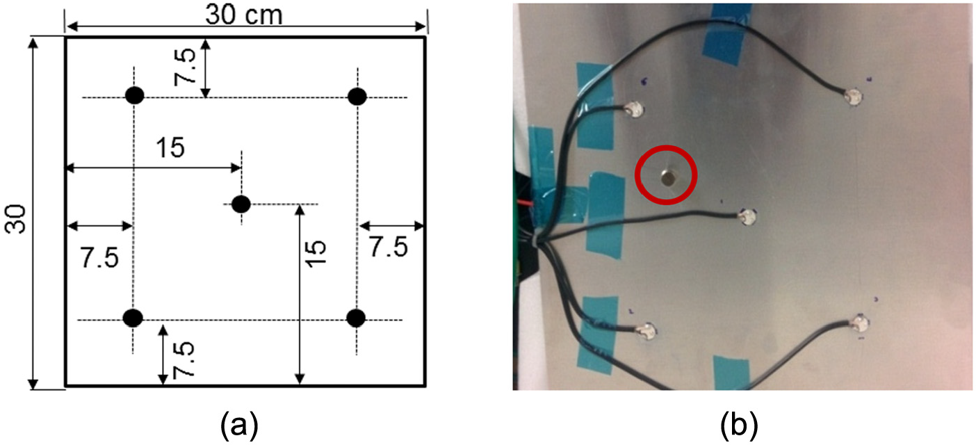
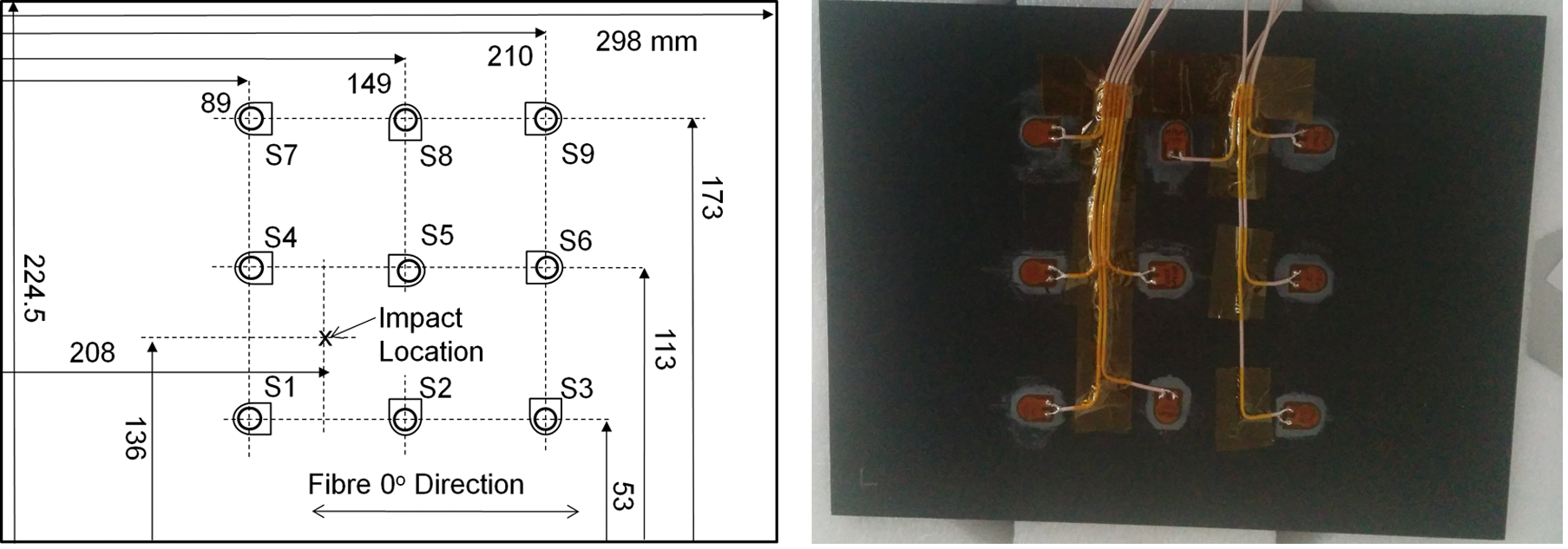
Experiments were conducted on an aluminium 6082 T6 plate of 1.3 mm thickness with a 5 and 12 sensor network (SN1 and SN2 plates) and aluminium 2024 T3 of thickness 1.4 mm (coupon plate). Both the SN1 and SN2 plates were of dimensions 30 × 30 cm, while the coupon plate measured 12 × 26 cm. It should be noted that only five sensors/actuators are used for damage detection in both the SN1 and SN2 cases as illustrated in Figures 5(a) and 7(a). For the aluminium plates (SN1, SN2 and coupon) Noliac NCE51 10 × 1 mm disc PZTs with coaxial cables were attached to the plate using cyanoacrylate Loctite 401 adhesive.
(a) Aluminium (SN1) plate and (b) picture of artificial magnet damage highlighted with circle.
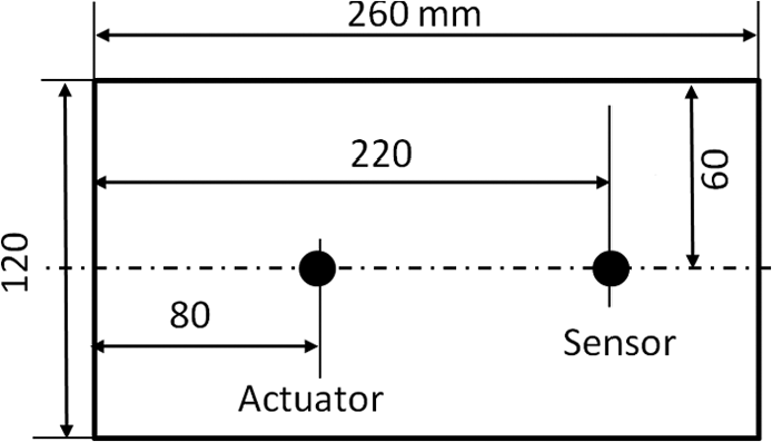
Schematic of the coupon aluminium plate.
For the coupon and SN1 plate, an Instron temperature control chamber was used to expose plates to elevated temperatures. The SN2 plate was exposed to temperature conditions in a TAS ECO 135 environmental test chamber. The plates were allowed to reach thermal equilibrium with an isothermal profile by allowing the chamber to stabilise for at least 30 min and measuring the plate temperature with k-type thermocouples. A set of 1 cm diameter Neodymium disc magnets, coupled to the plate with water, were used as artificial damage. For the SN2 plate, a 0.5 × 30 mm slot was machined to simulate a crack (Figure 7). The plates were excited at 300 kHz as this was found to produce large amplitude S0 symmetric modes with good sensitivity to the simulated damages.
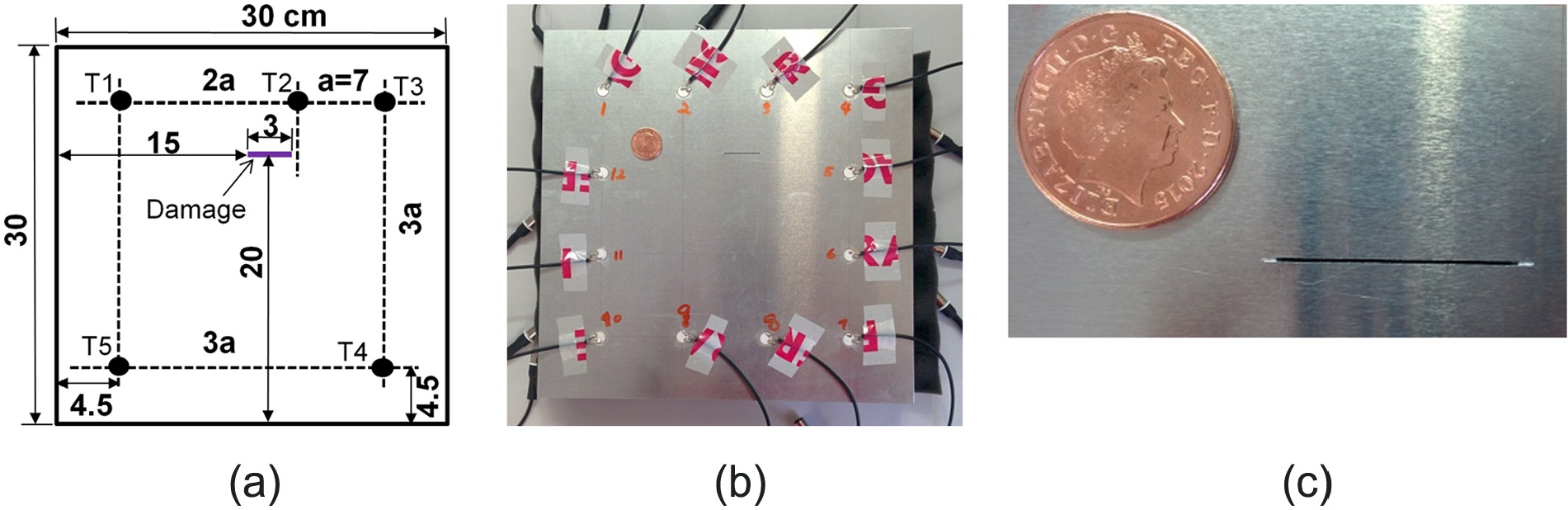
(a) Sensor network 2 (SN2) plate layout, (b) picture of actual plate and (c) crack.
Aluminium plate damage
The adopted damage detection strategy makes extensive use of the envelope of damage scattered signal, with the amplitude and TOF of the waves crucial for damage detection. In a qualitative preliminary study, different damage types were compared in terms of the residual levels caused between the damaged and pristine state signals.
A crack/notch of size 10 × 1 mm (smaller than that used by Sohn (2011)), hole of diameter 10 mm, a pair of disc magnets above and below the plate, BluTack mastic, large clamp and a large glued on mass were used to simulate damage scattering. Pictures of the six damage representations tested experimentally and the corresponding residual envelopes are shown in Figures 8 and 9, respectively.
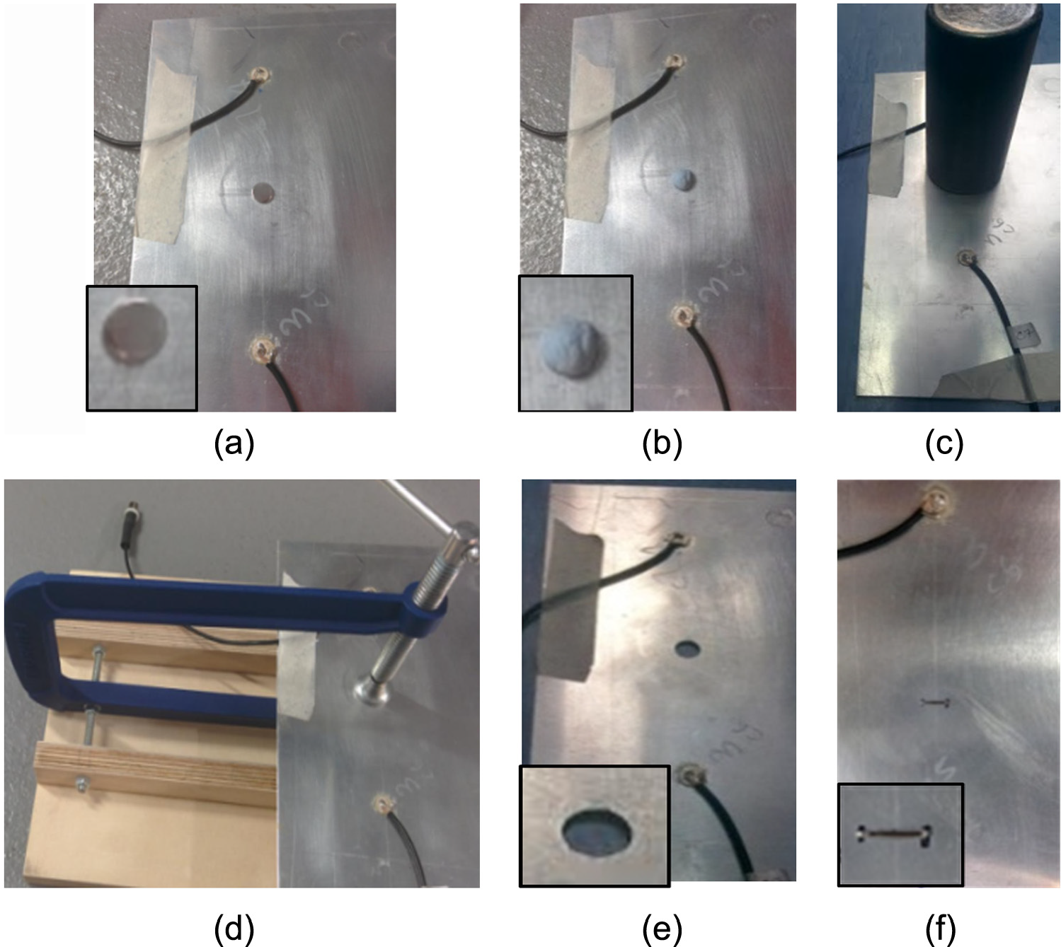
Different artificial damages (a–f) on an aluminium plate: (a) disc magnet, (b) BluTack, (c) large mass, (d) clamp, (e) hole and (f) crack/notch.
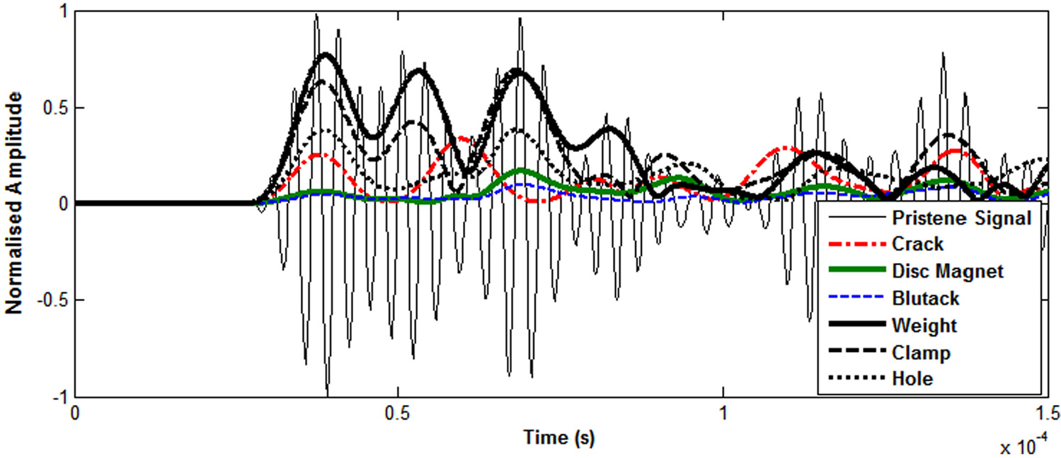
Residual envelope for different simulated damage types. Experimental results for 1.4 mm thick aluminium plate excited at 300 kHz (frequency thickness 420 kHz mm dominant symmetric mode).
As it can be seen in Figure 10, the disc magnets and the BluTack cause a similar level of scattering, smaller than that caused by the crack/notch and the hole. If damage scatter is smaller, it is more likely to be masked by residual brought about by temperature change. The clamp and the glued on mass also caused scattering that were comparable to each other, but higher than the other cases. Only the limiting case of damage in the direct path was considered with damages centred at the same point, without considerations for damage scatter directionality. It should be stressed that in all cases the TOF (of the first packet) in the simulated damage scatter was preserved, as the position of simulated damage was the same.
CFRP plate used for temperature compensation.
The aim of using a simulated damage is to introduce a scatter source not present in the baseline case, then applying the compensation and damage detection method to detect and localise the source of the scattering. For experiments, a small 1 cm diameter × 0.2 cm thick disc magnet is placed both sides of the plate and a physical crack is used to represent damage.
Composite plate
A CFRP plate consisting of 16 unidirectional Hexply 914-TS-5-134 plies with layup [0, 45, −45, 90]2s was used with a thickness of 2 mm. Hexcel Redux 312 film adhesive was used to bond 9 PIC DuraAct transducers to one side of the plate (top side) as shown in Figure 10. The plate was excited with tone burst signals in the 50 to 300 kHz frequency range. The 50 kHz results were used in damage detection as it was found that the A0 mode produced was most sensitive to the impact damage that was present. Damage was induced in the plate using a low velocity impact of high energy representative of a tool drop or bird strike impact. The plate was impacted with energy of 4.82 J on the back of the plate. It should be noted that the damage was not visible on either surface of the plate. Before and after impact, a Dolphi cam handheld scanner was used to obtain C-scan results to confirm the formation of BVID.
Composite plate damage simulation
Damage in composite can be simulated by drilling holes or by placing Teflon patches during manufacturing. However, this may not be representative of actual delamination. In this work, BVID in the plate induced with a low velocity high energy impact. An Instron CEAST 9350 drop tower, shown in Figure 11, was used to impact the CFRP panel on the back of the plate. The hemispherical impactor had a radius of 20 mm and a mass of 2.41 kg. It was found that in this configuration, the damage formation threshold was 2 m/s with impact energy of 4.83 J. This impact energy was used to induce the lowest severity damage possible.
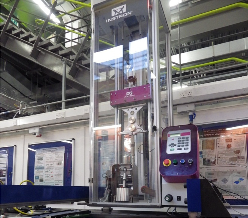
INSTRON CEAST 9350 impact machine used for impacting composite panel.
Experimental results and discussion
Artificial damage on aluminium plate
In this section, damage detection at different temperatures using raw, standard BSS and MBSS compensated signals are compared, with magnets representing damage. The data were obtained experimentally outlined in previous sections with results obtained at 300 kHz actuation (dominant symmetric mode).
Methods requiring a large baseline set to reduce the temperature difference between current and baseline results such as OBS and continuous baseline growth were not tested. The aim of this article was to investigate the robustness and the applicable temperature range of the compensation strategy proposed. The damage-free baseline signal was recorded at various temperatures in the environmental chamber. The current damage signal was then recorded in another location at a room temperature of 22°C–23°C.
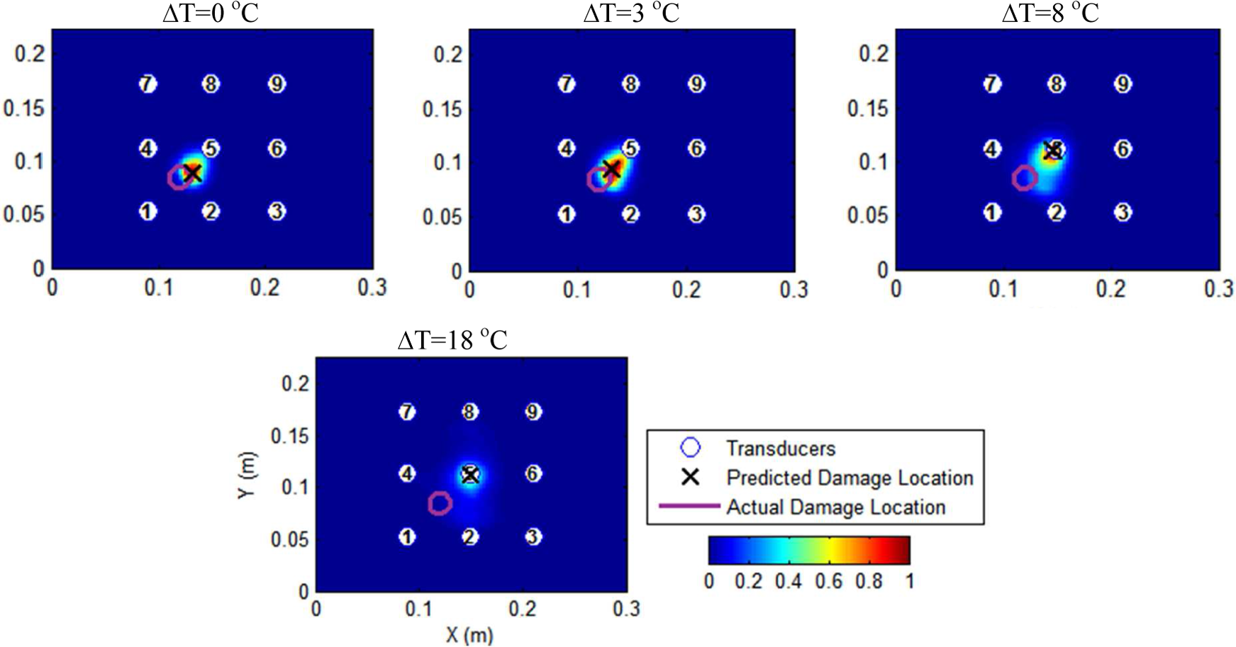
The damage location was predicted with good accuracy for baseline recorded at the same temperature with little to no noise as depicted in Figure 12. However, results for a temperature increase in 1°C–3°C showed a steep reduction in accuracy. Increasing the temperature difference further produced a square-shaped peak damage region in the middle of the plate, characteristic of the case where the residual becomes the envelope of the entire signal, that is, all damage scatter information is lost.
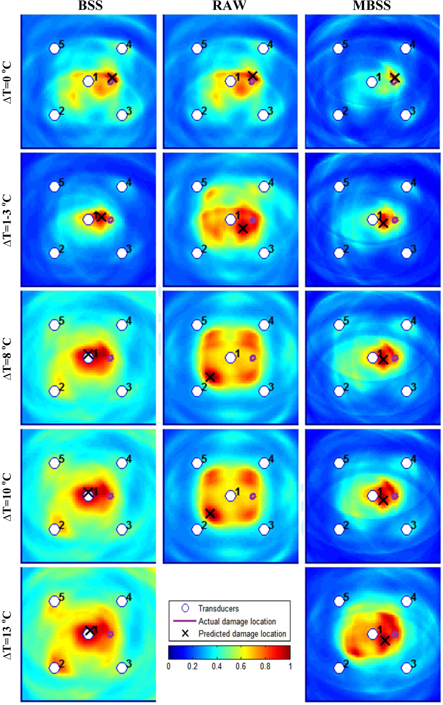
Damage location prediction maps at different temperature differences, for 1.3 mm thick aluminium plate SN1 at actuated at 300 kHz, using artificial magnet damage indicated on figures.
Next, temperature compensation schemes were implemented on the signals. The standard method was applied using the same stretch factor for the entire signal that most reduced the mean square error between the current and baseline signal. It can be observed in Figure 13 that temperature compensation does improve the results obtained up to 1°C–3°C for all methods. Above 3°C, the standard method produced poor results while modified method produced reasonable damage predictions up to a temperature difference of about 13°C.
Damage location predation maps with temperature compensation, for 1.3 mm thick aluminium plate SN1 at 300 kHz using artificial magnet damage. The modified BSS (MBSS) method giving improved localisation accuracy. Temperature difference and compensation method indicated below each subfigure.
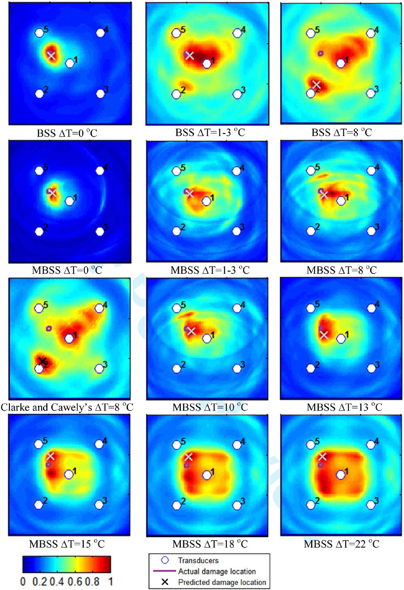
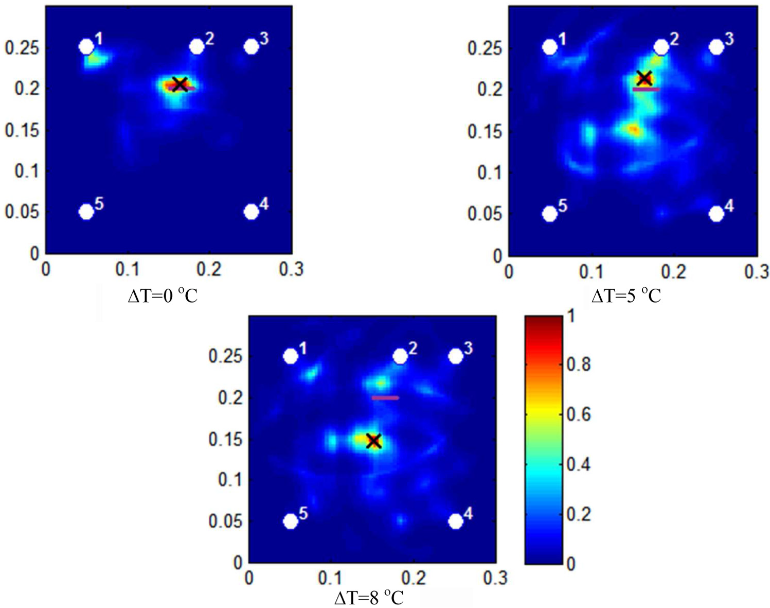
This was then repeated for another simulated damage location on the same plate (see Figure 14). As before, both standard and modified compensation performed well up to 1°C–3°C temperature change; the latter had better detections for temperature changes above this. This may not be immediately clear, but the predicted damage location is closer to the actual damage location and a smaller region of peak value prediction is present which encompasses the actual damage location. The limiting point method of Clarke and Cawley (2010) was applied with 100 limiting points and temperature difference of 8°C. There were reductions in the noise/artefacts; however, the accuracy of prediction did not significantly improve as shown in Figure 13.
Damage location predation maps for 1.3 mm thick aluminium plate SN1 at 300 kHz using artificial magnet damage. The modified BSS (MBSS) method giving improved localisation accuracy.
It should be pointed out that the scattered brought about by the disc magnets, used to simulate damage, was significantly less than that from a notch/crack. If the damage scatters is smaller, it is more likely to be masked by residual brought about by temperature change.
Crack damage on aluminium plate
The MBSS was demonstrated on the SN2 plate with a 0.5 × 30 mm crack centred at (0.165, 0.2) m. Only five transducers were used for damage detection, indicated on the normalised damage detection maps.
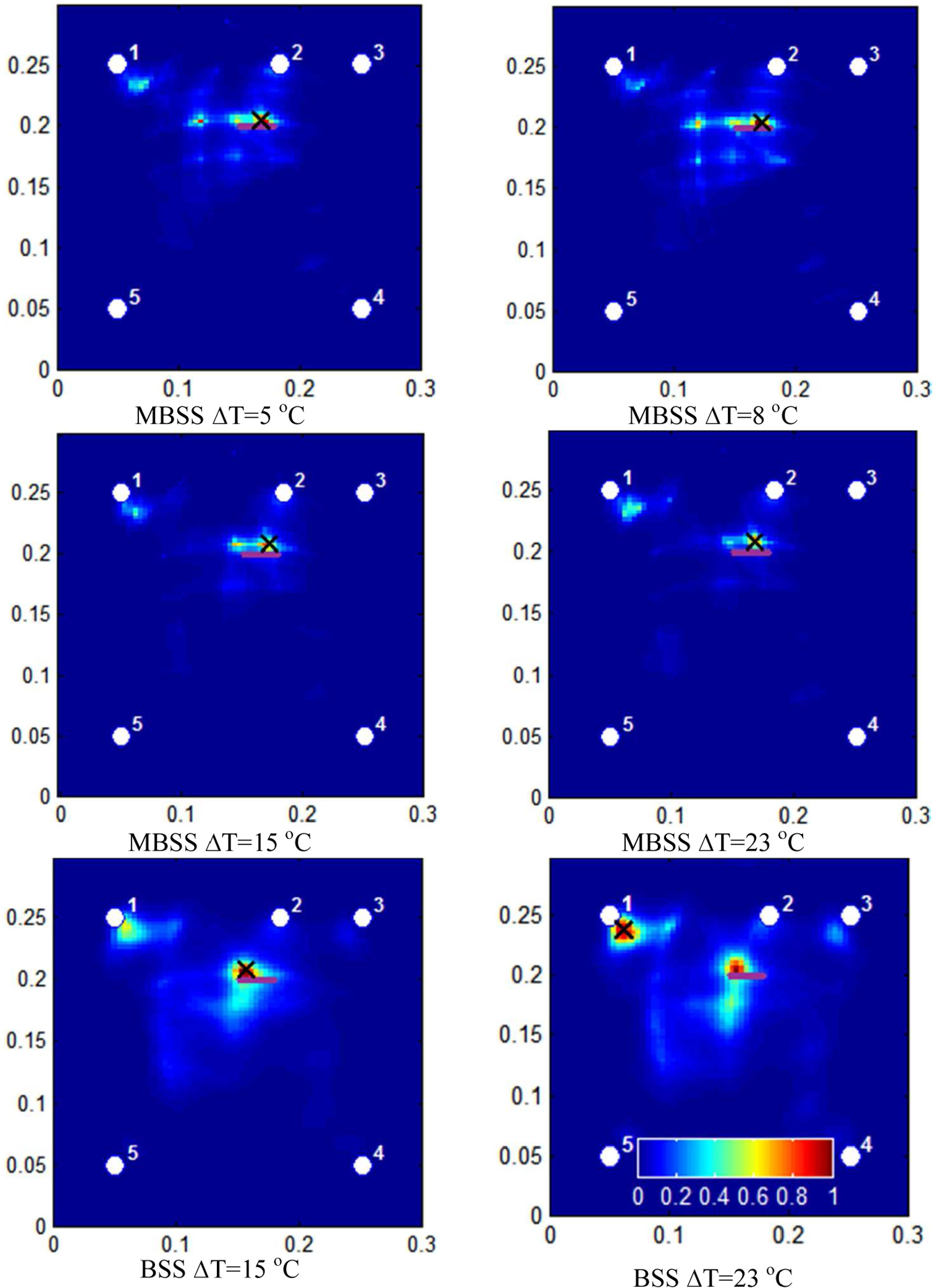
It was found that accurate prediction of the crack location could be achieved when there was no temperature difference between the baseline and current signal as shown Figure 15. As temperature difference increased, the detection accuracy reduced greatly with the location predicted incorrectly in the middle, far from the actual damage. Applying standard BSS and the developed modified temperature compensation methods, it was found that it was possible to obtain accurate damage location predictions at 15°C temperature change with both methods (see Figure 16). This temperature change was higher than the case of artificial magnet damage, as the scattering caused by the crack was larger and hence easier to detect as explained in Section 3.2 (Aluminum plate damage) It should be noted that at 23°C additional noise began to appear near sensor 1, similar to the case with no correction (see Figure 15) for both standard and the modified method. At 23°C, the standard method was unable to correctly predict damage location (see Figure 16), while the modified method still performed well with the crack location predicted accurately.
Damage location predation map without temperature compensation for 1.3 mm thick aluminium plate SN2 with crack, excited at 300 kHz.
Damage location predation map with modified BSS (MBSS) and standard BSS temperature compensation for 1.3 mm aluminium plate SN2 with crack, excited at 300 kHz. Difference in temperature and compensation method used indicated below each subfigure.
Impact damage on CFRP plate
The developed temperature compensation was used to detect impact damage in the CFRP plate. Presence of the impact damage was verified with conventional C-scan results shown in Figure 17. The BVID induced by the impact was roughly circular with a diameter of 2 cm.
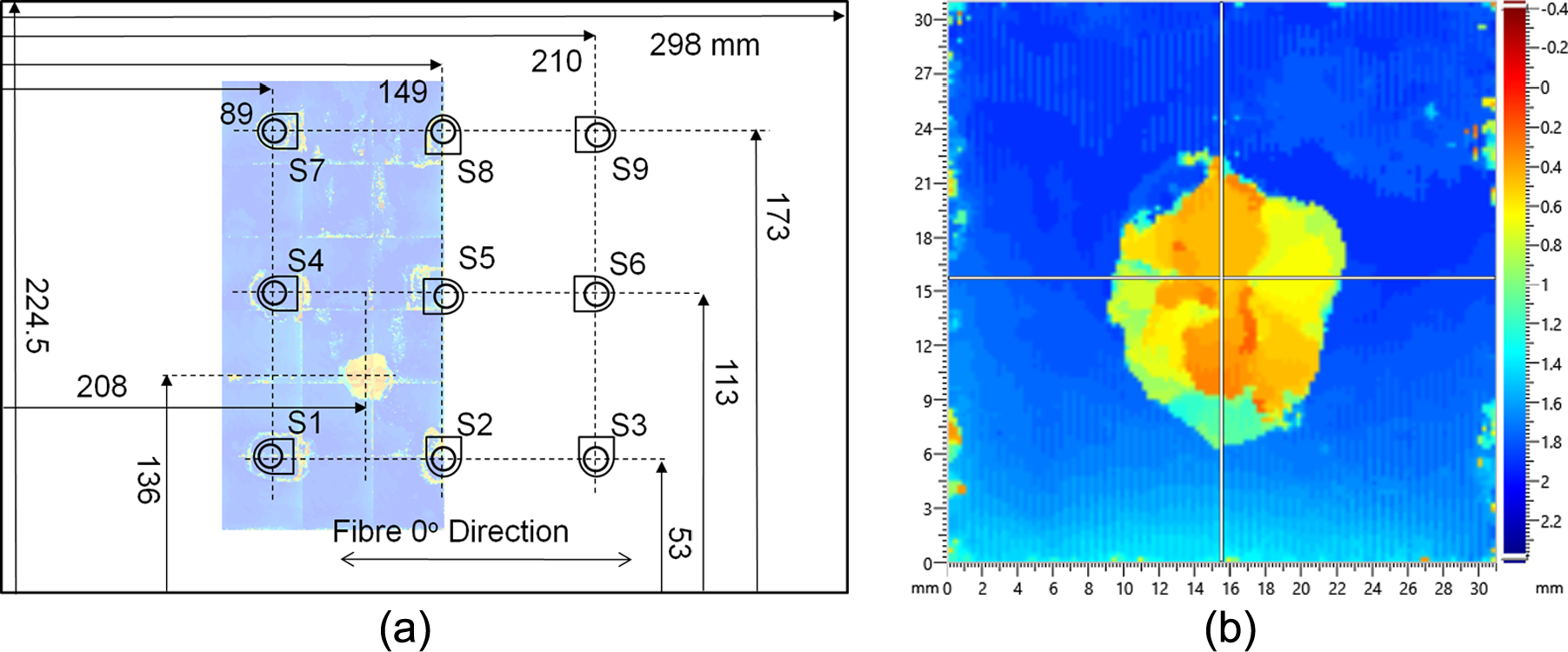
(a) C-scan of barely visible impact damage in relation to the top of the CFRP panel and transducers and (b) C-scan of damage size. (b) is mirrored and rotated in relation to (a) as it was scanned from the bottom side of the plate.
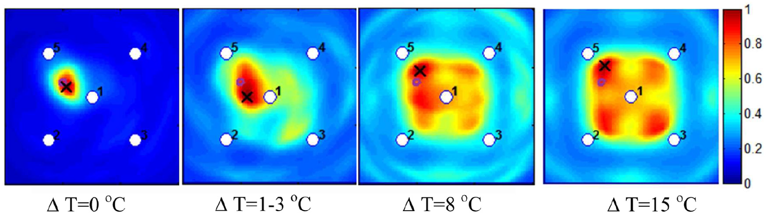
The damage detection approach was applied to the case of no temperature difference between the baseline and damaged signal, with the damage being localised and detected accurately as depicted in Figure 18. It should be noted that as expected with temperature difference between the baseline and damaged signal, there was a steep decline in localisation accuracy. Similar to the case of crack damage with increased temperature, the location prediction with the uncorrected signal moved towards the middle of the plate. At a temperature difference of 8°C, the damage was predicted, incorrectly, to be at the centre.
Impact damage detected on a CFRP panel without temperature correction. A 2 mm thick plate excited at 50 kHz with A0 dominant Lamb wave modes. Temperature difference between the current and damaged signal indicated.
Both the BSS and modified method were able to significantly improve the accuracy of the localisation at alleviated temperature differences as shown in Figure 19. Both compensation methods yielded similar accurate location predictions at 8°C temperature difference. Damage predictions were within the actual damage area for the BSS and modified method. At around 18°C difference, the BSS location prediction began to move to the centre of the plate, characteristic of the uncorrected case. The modified method maintained the same location prediction as lower temperature changes. The MBSS compensation method yielded accurate damage localisation up to 28°C difference, with location prediction within the area of the actual damage. Therefore, the proposed method can be used to accurately localise damage over much larger temperature range.
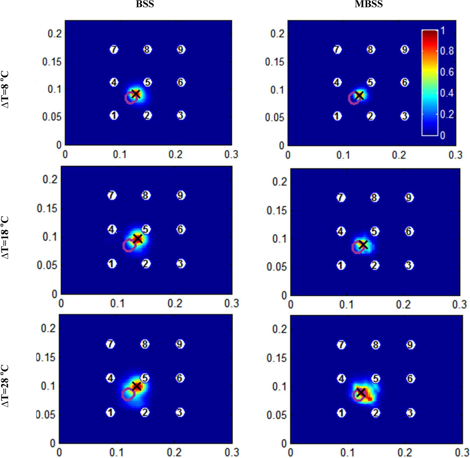
Impact damage detected on a CFRP panel with temperature correction. A 2 mm thick plate excited at 50 kHz with A0 dominant lamb wave modes. Temperature difference between the current and damaged signal indicated.
Conclusion and future work
A new method of temperature correction was proposed and used in conjunction with a delay and sum damage detection algorithm. The proposed method directly corrected the residual envelope and is able to deal with higher temperature differences. It was shown that the existing BSS temperature compensation strategy is only effective for temperature difference of around 1°C–3°C when detecting a small artificial damage (dual magnet). The modified method was shown experimentally to be more effective than BSS for temperature differences of up to 13°C for this artificial damage type.
The proposed method was also applied to the case of actual crack damage representative of fatigue in an aluminium plate. The developed method was found to be effective for temperature differences of up to 23°C, while BSS only up to 15°C for detecting the crack location. The method was then verified with an actual case of impact damage on CFRP panel with the proposed method outperforming the BSS method. The results are summarised in Table 1.
Summary of result indicating the largest temperature change for which the damage could be accurately localised by applying temperature correction methods: BSS and MBSS.
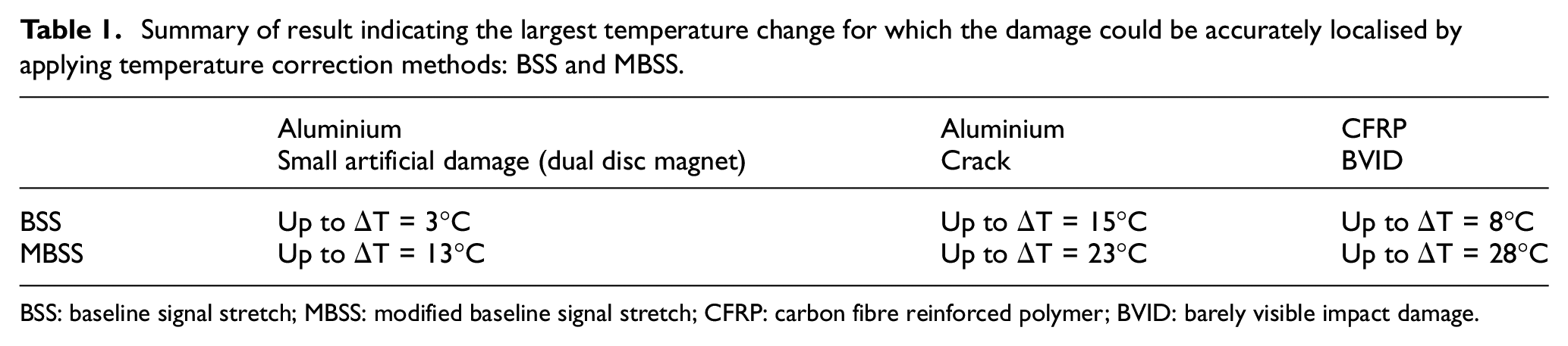
BSS: baseline signal stretch; MBSS: modified baseline signal stretch; CFRP: carbon fibre reinforced polymer; BVID: barely visible impact damage.
Footnotes
Declaration of Conflicting Interests
The author(s) declared no potential conflicts of interest with respect to the research, authorship and/or publication of this article.
Funding
The author(s) disclosed receipt of the following financial support for the research, authorship, and/or publication of this article: This research was funded by the UK Engineering and Physical Sciences Research Council (EPSRC) Doctoral Training Account (DTC).