
Abstract
Chattering in the impact damper refers to a continuous impact phenomenon during vibration. This paper establishes the dynamic model of the nonfixed constrained vibro-impact system on the base of classical impact damper. The chattering occurrence in the low frequency range is studied by numerical simulation. The results show the frequency ratio and clearance significantly affect the system’s chatter behavior: (1) Chattering is prone to occur in the low frequency range. As the frequency ratio decreases, the number of unilateral continuous impacts between the primary system and the small ball (the free mass) increases from one impact to multiple impacts, and a viscosity behavior appears under the condition of low frequency ratio. (2) Small clearance is prone to chattering. With the increase of the clearance, the frequency ratio range of the chattering in the system decreases. When the clearance exceeds a certain critical value, the system will not experience chattering behavior.
Introduction
As a passive control technology for vibration, impact damper uses the impact between the free mass and the primary system during the vibration to control the main system’s response. The current research findings on impact damper employ two symmetric impacts per cycle as the typical motion model for impact dampers.1–3 Based on the numerical stimulation, it was discovered that there are observable chattering and viscosity phenomena in the motion trajectory under the condition of better damping effect, that is chattering and viscosity are probably new, effective approaches for the impact damper to achieve good damping effect. The term chattering refers to a condition when there are multiple or even unlimited times of impacts between the free mass and the primary system in a short period of time. The term viscosity is defined as a situation under which the free mass moves with the primary system synchronously.
In regard to studies on chattering, Budd and Dux 4 conducted a systematical research on the chattering and viscosity motions of the single-freedom impact primary system under periodical excitation and deduced the existence of the system’s periodical chattering behavior as well as the relationship between the periodical chattering behavior and the chaotic motion. In Toulemonde and Gontier’s study, 5 on dynamic behavior of the impact primary system of the harmonious excitation, the researchers identified viscosity motion and thereby conducted a study on the periodical viscosity motion for both single freedom and multiple freedom. Wagg and Bishop6–9 studied the periodical movement, the chaotic chattering motion, and the viscosity motion in a harmonious excited two‐degree‐of‐freedom impact vibration system. In the study on the chattering and viscosity motions, they observed slip bifurcation and the “uplift” phenomenon, and then discussed the conditions needed for the appearance of viscosity phenomenon in bilateral-restrained impact system. Demeio and Lenci 10 studied an approximate calculation method for the chattering duration time in an inverted pendulum collision. The study revealed that the chattering duration time was primarily associated with the amplitude instead of the excitation frequency or the damping ratio. Using experimental and numerical approach, Alzate et al. 11 conducted a research on the chattering behavior of the impact model based on the gear transmission system. By introducing the local discontinuity mapping algorithm, Nordmark and Piiroinen 12 studied the stability and bifurcation of chattering behavior in collision system. Quintana and Ciurana 13 summarized the research progress, methodology, and classification of chattering in both industry and academic research. Besides, Hős and Champneys 14 studied the impact model based on the pressure relief valve, by discussing the model’s bifurcation, chattering behavior, and the path from bifurcation to chattering. Yang et al. 15 employed the equivalent linearization and numerical simulation methods to accomplish a research on the wing flutter suppression with impact damper. Yin et al. 16 studied the issue of the collision between a cantilever and a steel bar and discovered both chattering and viscosity phenomena. Luo et al. 17 studied the two-degree-of-freedom impact system with rigid constraint and disclosed the presence of chattering and sticking phenomena under the low frequency condition. Based on the case of a typical Duffing unilateral impact system, Feng et al. 18 studied the system’s complete chattering and noncomplete chattering phenomena and in the meantime analyzed the chattering bifurcation in the system. Li and Ding 19 carried out an analysis on the sticking motion in a vibro-impact system with multiple constraints. Zhang et al. 20 established a Poincaré mapping based on the dynamic model of two-degree-of-freedom impact system with clearance and precompressed spring, and then deduced the Jacobian matrix of the mapping. Su and Wang 21 derived the analytical solution as well as the Poincaré mapping of the periodical movement of two-degree-of-freedom impact system with unilateral rigid constraint, analyzing the system stability of periodical motion and the system bifurcation phenomenon and chaotic evolution under appropriate parameters. Zhu and Luo 22 applied the numerical simulation method to their study on the chattering motion and its transition law of two degree of freedom with soft impacts. Du 23 developed a simplified two-degree-of-freedom model to obtain the chattering completion point and the chattering time in impact damper.
At present, the researches on chattering and viscosity seldom involve the damper and the existing research models have fixed constraints whose amplitudes have been limited to a certain range. 23 Since the constraint in impact damper is a free mass with unset position, an unfixed constraint model is needed. Therefore, the study of the chattering in impact damper in this paper differs significantly from the existing ones. Establishing a dynamic model of an unfixed constraint, this paper studies the conditions of the chattering occurrence in impact damper.
Dynamic model of vibro-impact system
Based on the model of impact damper, the dynamic behavior of impact damping system is studied. The system’s mechanical model is shown in Figure 1.
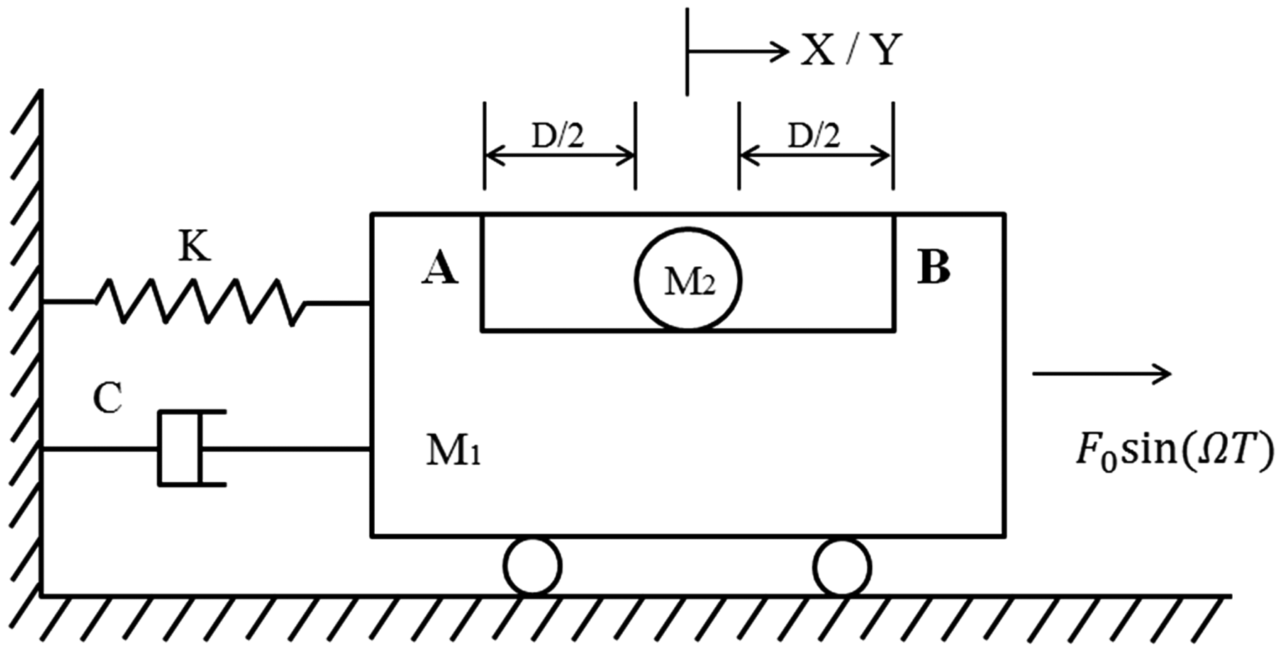
Model for impact damper.
Figure 1 shows a dynamic model of impact damper. Due to the effect of harmonic excitation force F0sin(Ωt), a primary system with mass M1 is connected to the support by a linear spring with stiffness K and a linear damping with damping coefficient C. The ball with a mass of M2 moves horizontally in the primary system slot. Taking the central point of the primary system as the origin of coordinate, the relative displacement between the small ball and the primary system is equal to D/2 (or −D/2). They impact each other and then continue to move with new initial velocity until the next time of impact. As it is repeated, the generated momentum exchange thereby consumes a part of the mechanical energy so as to achieve the vibration reduction. For the simplification of calculation, here are a couple of basic assumptions:
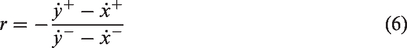
The primary system and the small ball are two completely independent objects whose motion rules are not mutually influenced but are only related to each other during the collision. The impact between the primary system and the small ball occurs in a moment, that is the collision only changes the velocity of the primary system and the ball, and does not change their displacement (to satisfy the law of conservation of momentum). The energy dissipation of damper is dominated by collision energy dissipation and the friction among each component can be neglectable. The collision is inelastic and is represented by coefficient of restitution r. Only collision vibration in the horizontal direction is considered.
Kinetic equation of vibro-impact system
According to Figure 1, the small ball M2 is considered to be uniform linear motion without collision


When there is no collision, the differential equation of motion of the primary system M1 is


When

Influence of frequency ratio on the chattering occurrence condition
In terms of the description of the chattering phenomena, as shown in Figure 1, only baffle A is taken into consideration regardless of baffle B. When the small ball moves to the left, it collides with the baffle A on the left; as the ball continues to move to the right, the primary system catches it from behind and the collision happens. Such collision happens repeatedly and may result in two results: (1) The chattering between the primary system and the small ball is not convergent, and they separate after a certain impact and no longer collide, which is referred to as noncomplete chattering. (2) The chattering between the primary system and the small ball converges to the same speed, and then they move at the same speed, which is expressed as viscosity, referred to as complete chattering.
Figure 2 indicates the bifurcation diagram of the primary system when the instantaneous velocity after the collision falls in the range where the frequency ratio is ω = 0–30. It can be observed in the figure that, in the interval ω∈(2,30), the response in the vibro-impact system shows as a steady-state one; as the excitation frequency ω declines gradually, the system response shows a leaping, paroxysmal bifurcation. For a more detailed understanding of the collision between the primary system and the small ball in the vibro-impact system, the time-domain diagrams of the relative displacements between the primary system and the small ball in the vibro-impact system are obtained by using numerical simulations when ω = 0.4, 4, 6, 8, 11, 12.5, 18,25, respectively, as shown in Figure 3.
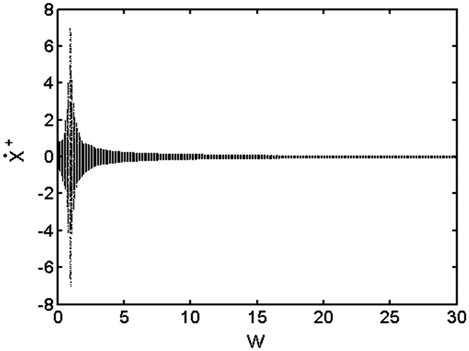
Bifurcation diagram of
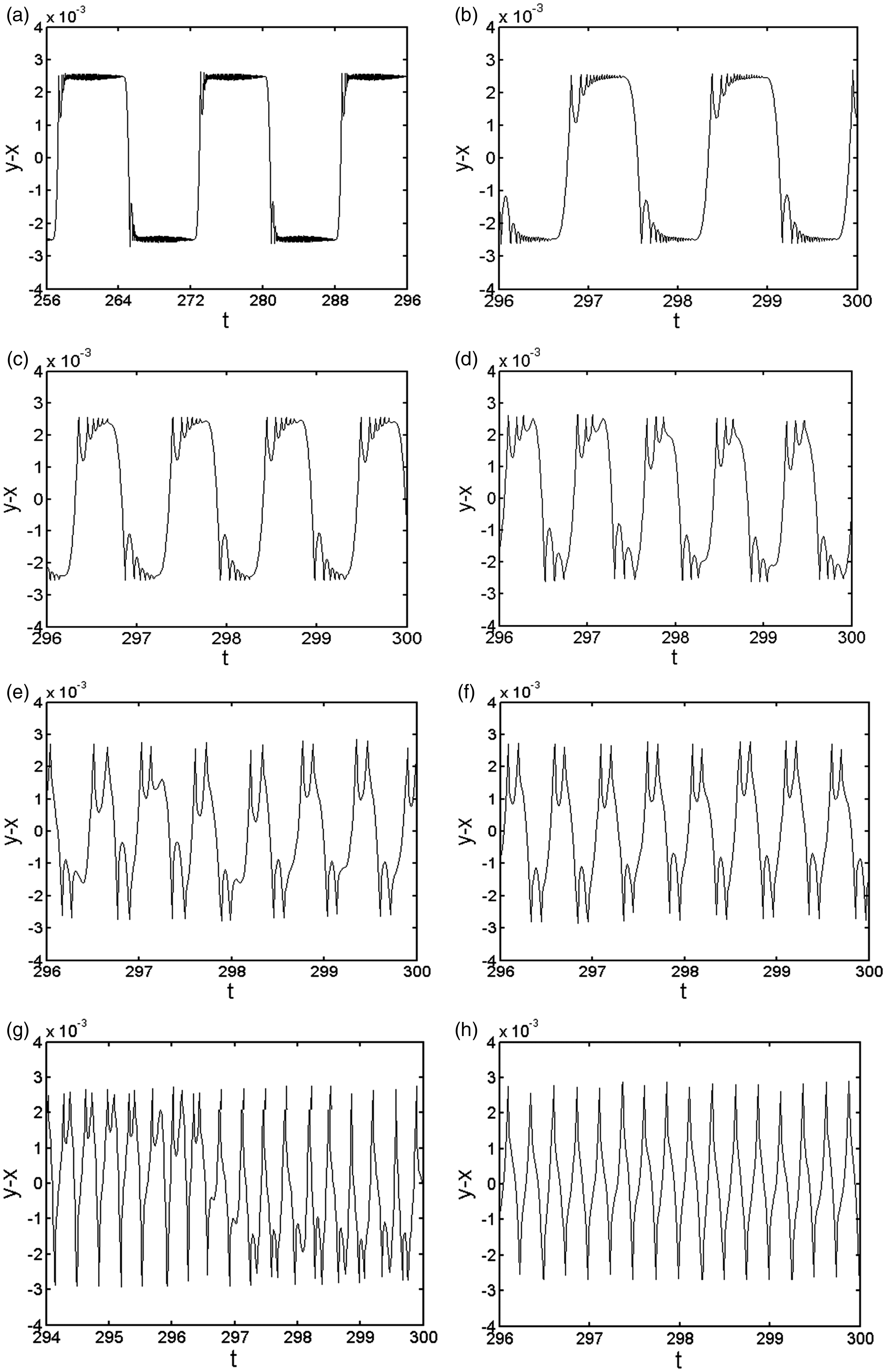
Time-domain diagram of relative displacement of main system and free mass in different frequency ratio: (a)
Figure 3 provided the time-domain diagram of the relative displacement between the primary system and the small ball under different frequency ratio. It can be observed from Figure 3 that, when ω = 0.4 in Figure 3(a), there are successive, multiple collisions between the primary system and the small ball in a short period of time. As the frequency ratio increases gradually, the number of collision between the primary system and the small ball varies from unilateral, multiple times (more than 15 times) successive collisions to unilateral, one-time collision: unilateral, multiple times collisions (Figure 3(a)) → unilateral, 15 times collisions (Figure 3(b)) → unilateral, six times collisions (Figure 3(c)) → unilateral, three times collisions (Figure 3(d)) → unilateral, two times collisions + one time, no collision (Figure 3(e)) → unilateral, two times collisions (Figure 3(f)) → interval, unilateral, two times collisions (Figure 3(g)) → unilateral, one time collision (Figure 3(h)).
In Figure 3, with the definition of chattering in this paper, it is shown that there is an approximately periodical chattering behavior when the vibro-impact system is under a relatively low frequency ratio circumstance. For the purpose of obtaining the frequency ratio interval of the system’s chattering under this parameter condition, the following discussion is conducted with the frequency ratio interval being ω∈(6,8).
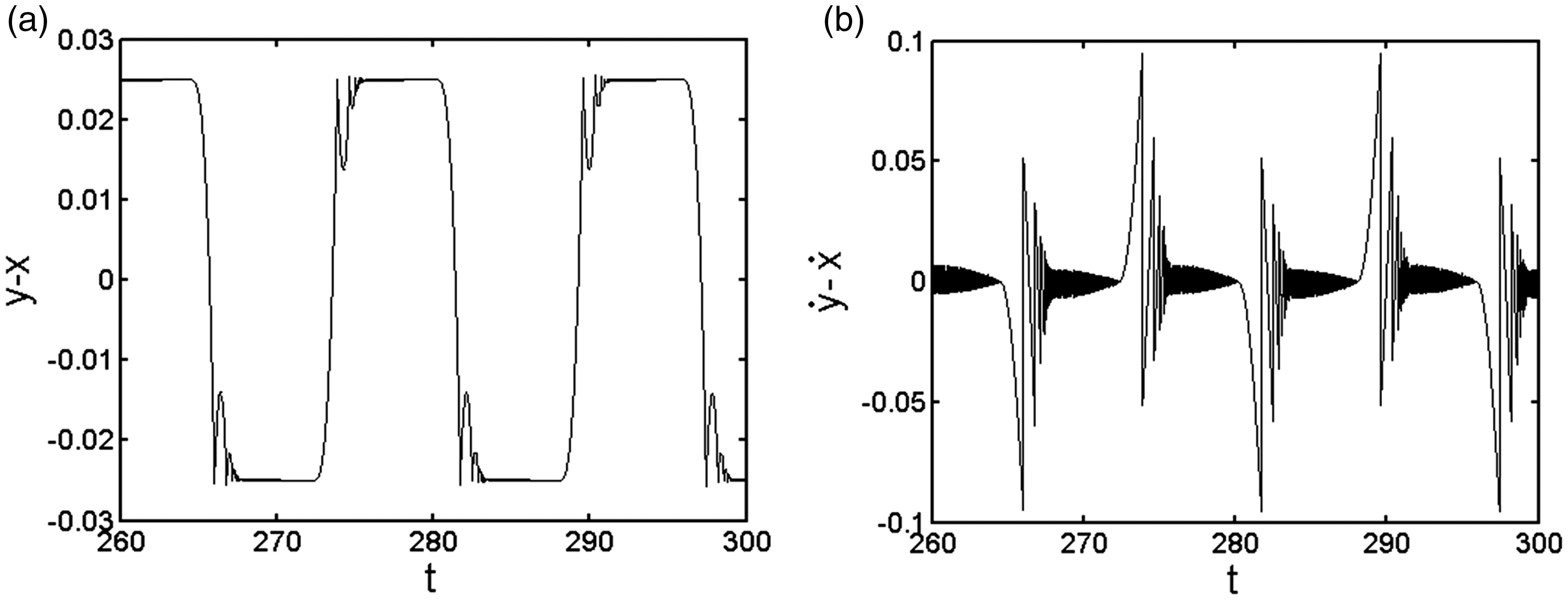
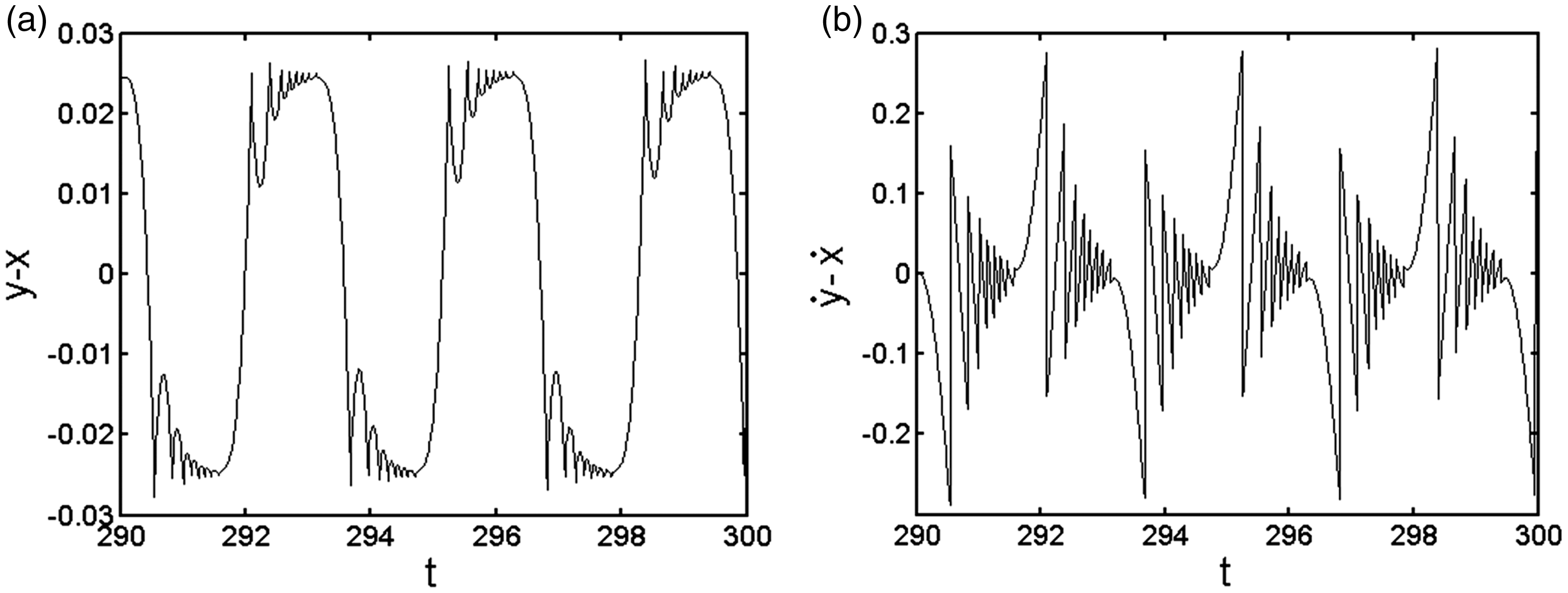
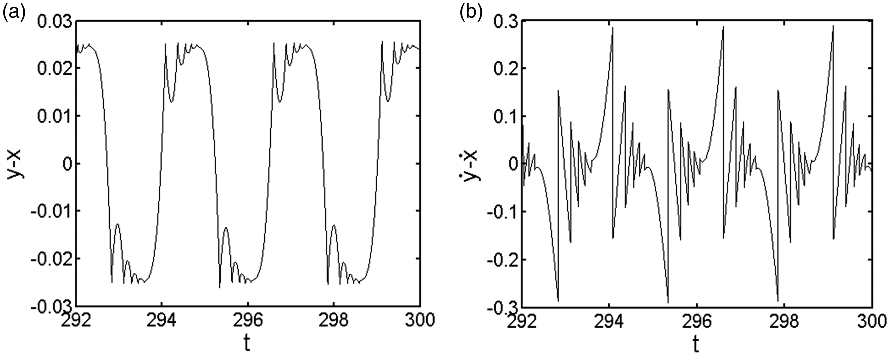
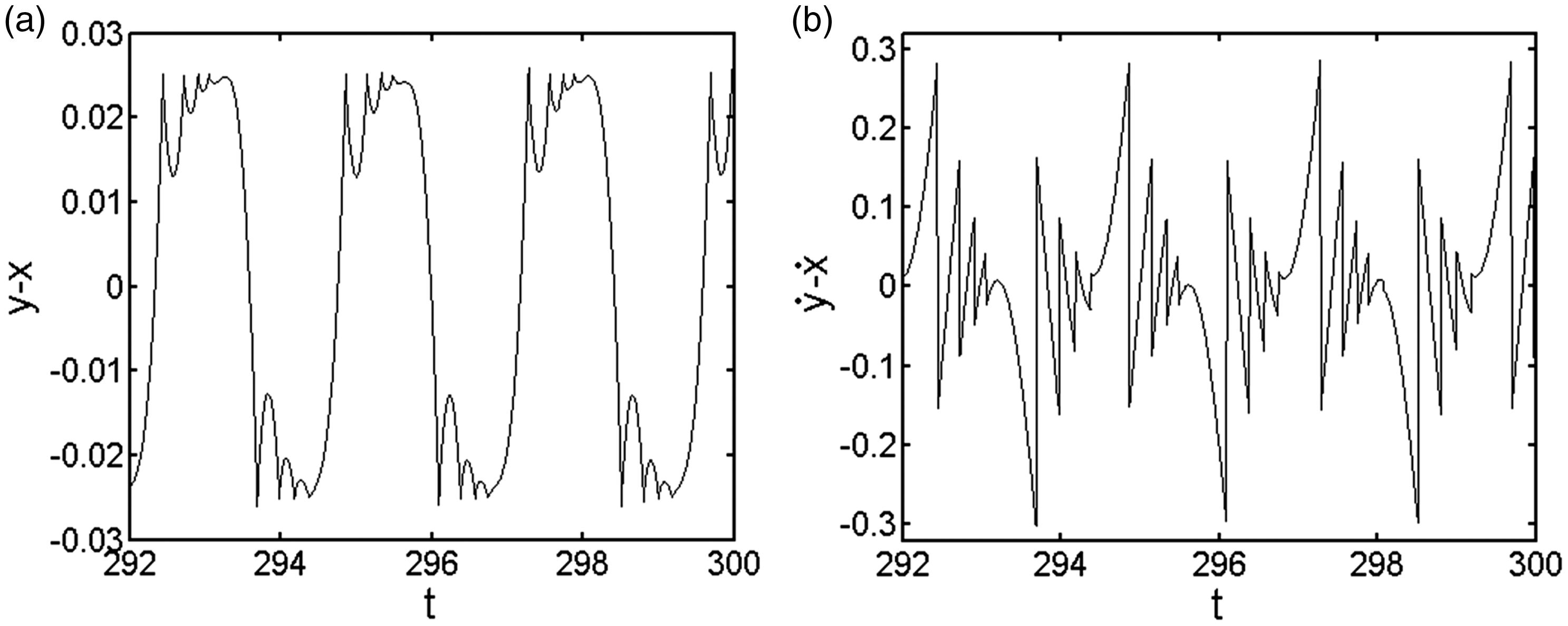
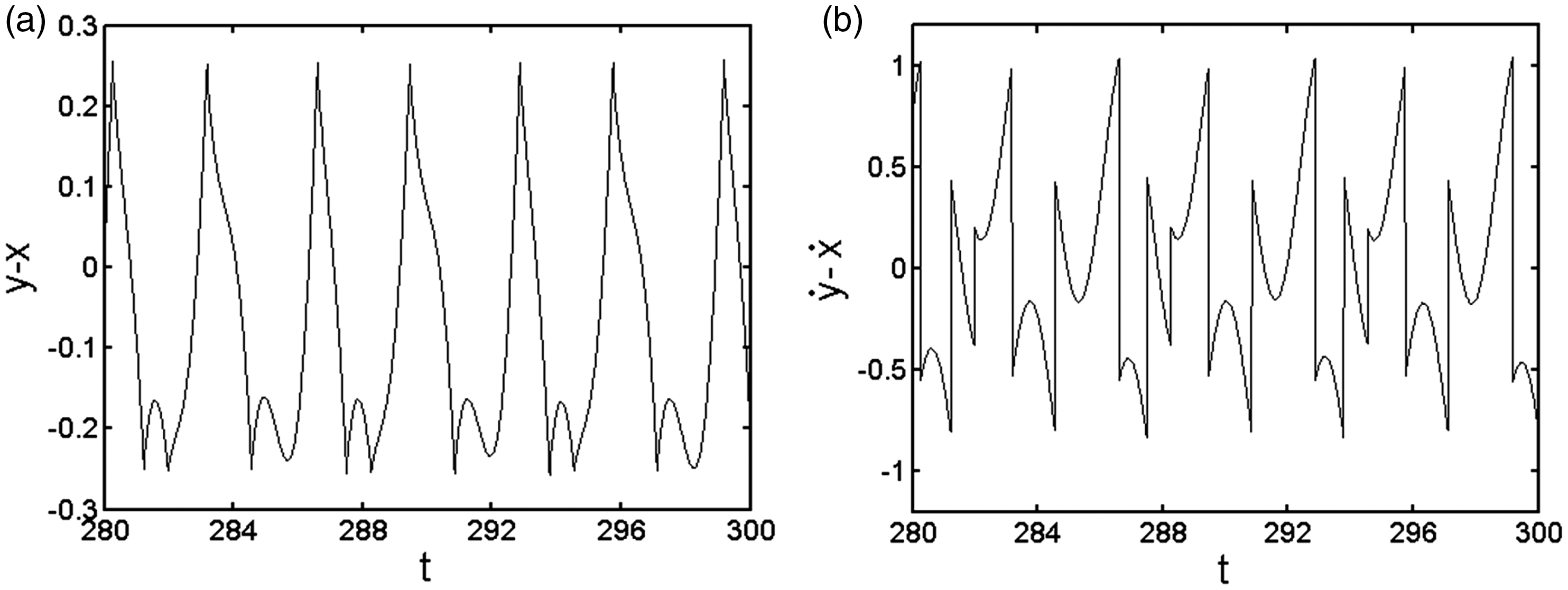
Figure 4 represents a response diagram of the relative displacement and relative velocity of the primary system and the small ball varying with time, when ω has different values under the interval (6, 8). From Figure 4, when ω = 6.8, the primary system and the small ball have five times of unilateral, continuous collisions (Figure 4(c)), and as the value of ω increases and exceeds ω = 6.8, the unilateral, continuous collisions between the primary system and the small ball will be less than five times. In this paper, it is defined that the chattering behavior occurs when the primary system and the small ball collide continuously five times or more on the single side.
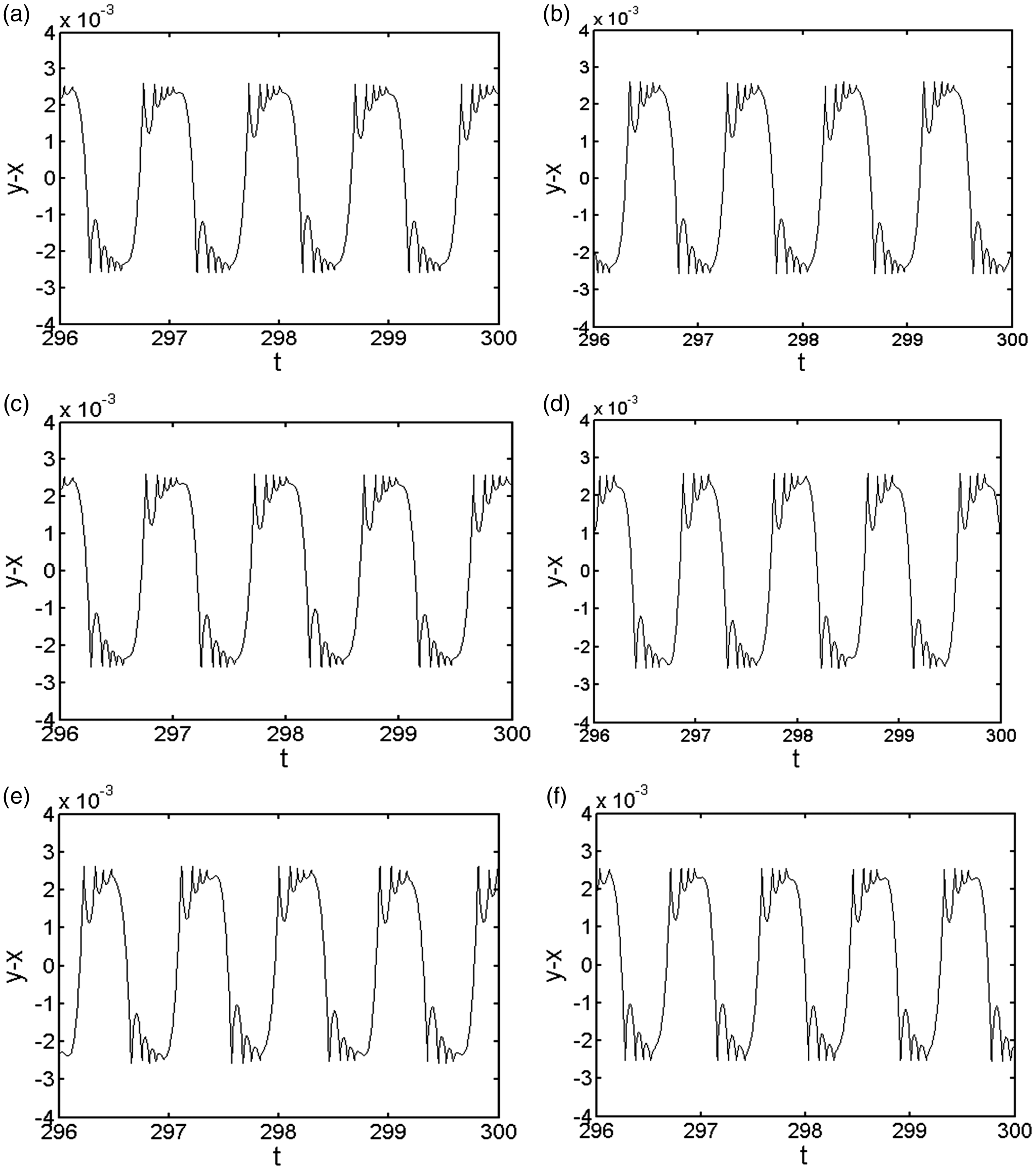
Time-domain diagram of relative displacement of main system and free mass in different frequency ratio. (a) ω = 6.5, (b) ω = 6.7, (c) ω = 6.8, (d) ω = 6.9, (e) ω = 7.0, and (f) ω = 7.2.
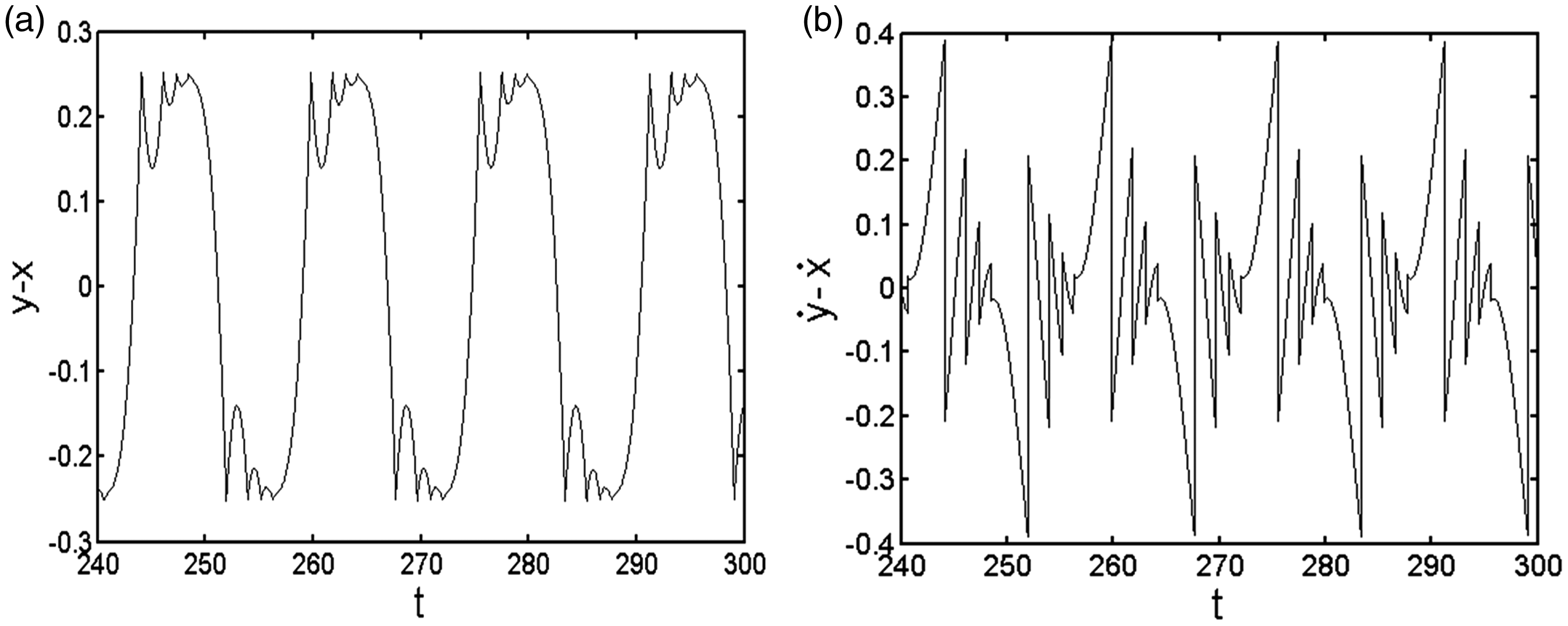
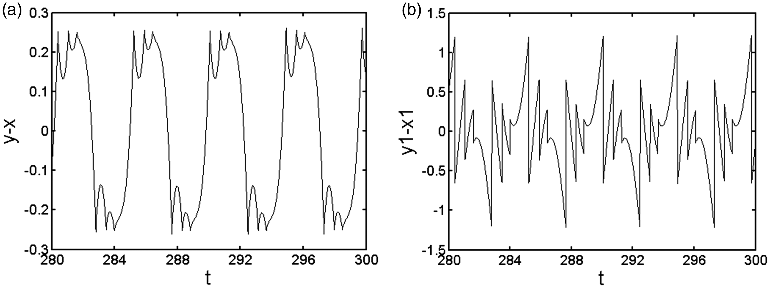
As a result, the frequency ratio interval of the chattering is ω∈(0, 6.8) under such system parameter circumstance. For a clearer observation of the chattering behavior when the frequency ratio is relatively low, the situation of ω = 0.2 (Figure 5(a)) is partially enlarged (Figure 5(b)). It can be clearly noticed in Figure 5(b) that there are multiple times, unilateral, continuous collisions between the primary system and the small ball in a short period of time, and the relative displacement and relative velocity are converging, respectively, to the clearance value and the zero value. Also, the displacement difference is 1 × 10⁻⁵, less than 1000th of the primary system’s maximum amplitude value (with the maximum amplitude being 1.02), which meets the criterion for chattering behavior in this paper and thereby it is considered that the system has a complete chattering behavior under this parameter condition.
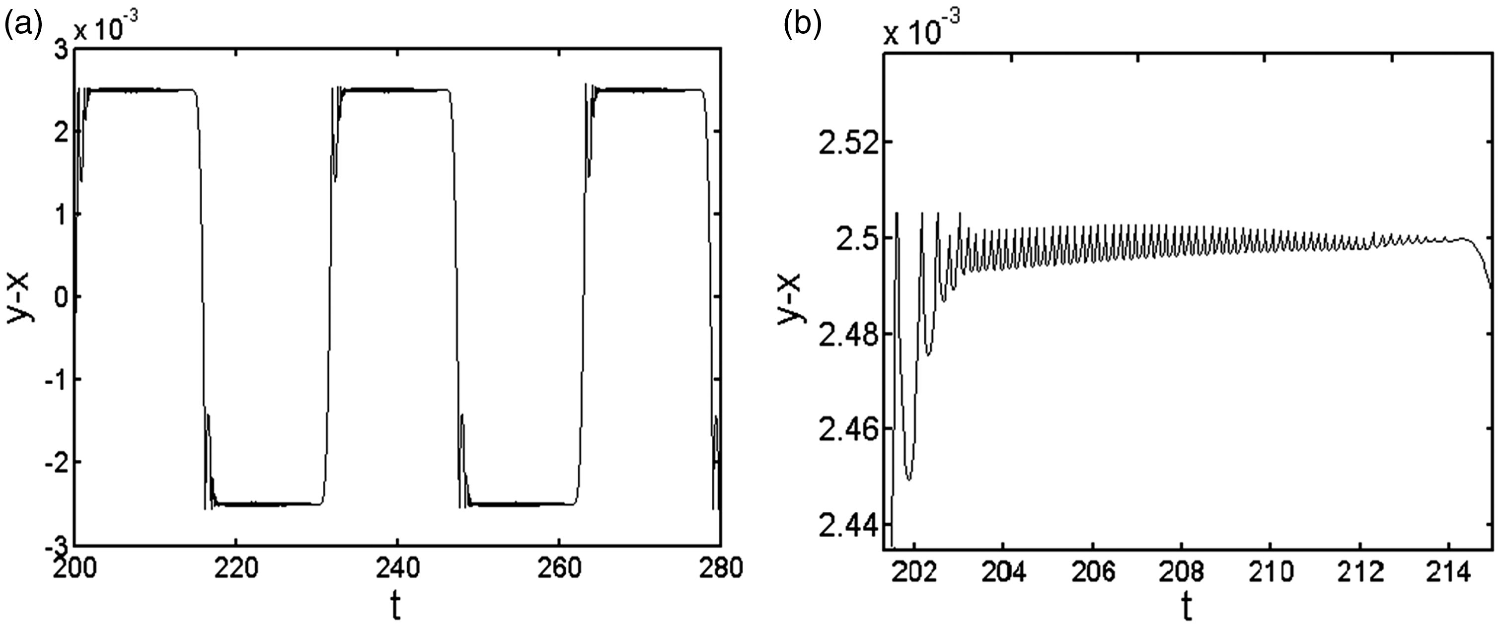
Time-domain diagram with
Influence of clearance on chattering occurrence
Analysis of chattering with clearance δ = 0.008
In order to study the effect of clearance on the chattering occurrence in a vibro-impact system, when the system parameters
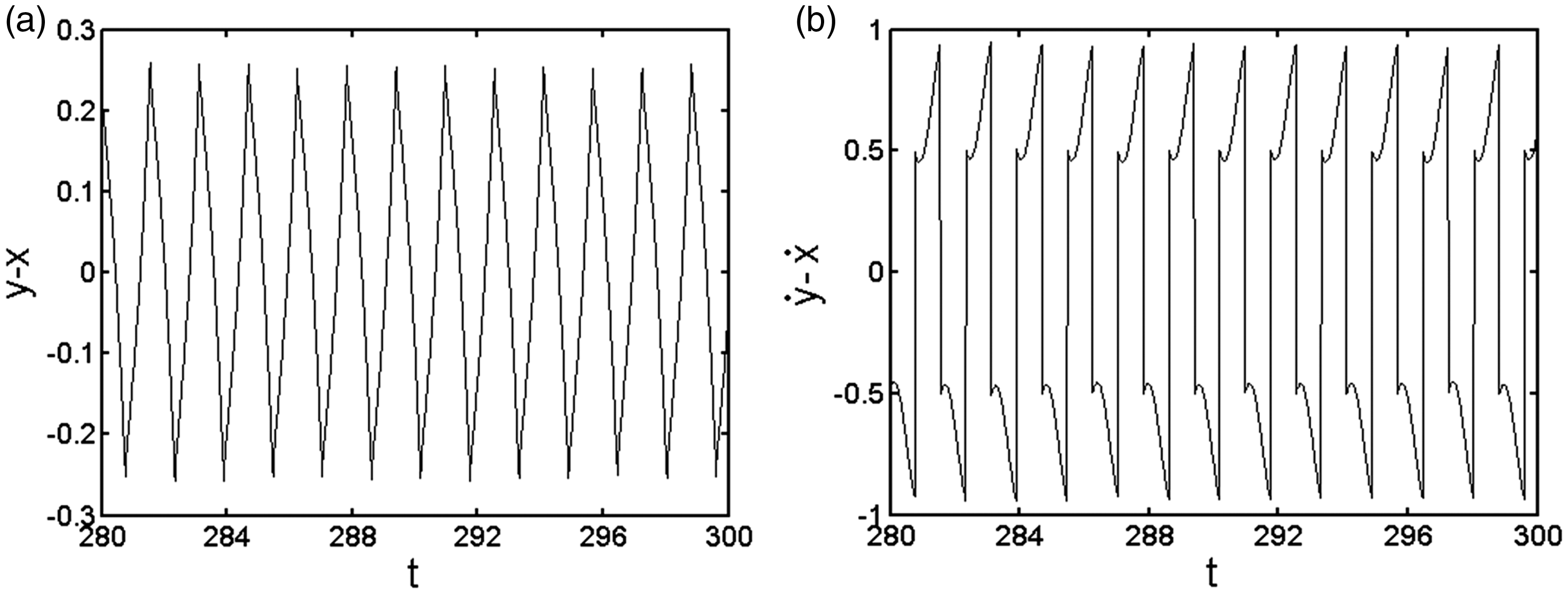
From Figures 6(a), 7(a), and 8(a), it can be seen that there are unilateral, multiple times, continuous impacts between the primary system and the small ball in the impact damper, and the corresponding velocity time-domain diagrams (Figures 6(b), 7(b), and 8(b)) indicate that the relative velocity of the primary system and the small ball fluctuates around the zero value, converging to the zero value, that is the system experiences chattering at the point. In Figure 9(a), the primary system and the small ball in the impact damper continuously collide unilaterally, and the impact times vary between 4 and 5, which is considered as the critical value of the chattering behavior under this frequency ratio. That is, under such clearance parameter condition, the frequency ratio of chattering behavior has an interval of ω∈(0, 5.6).
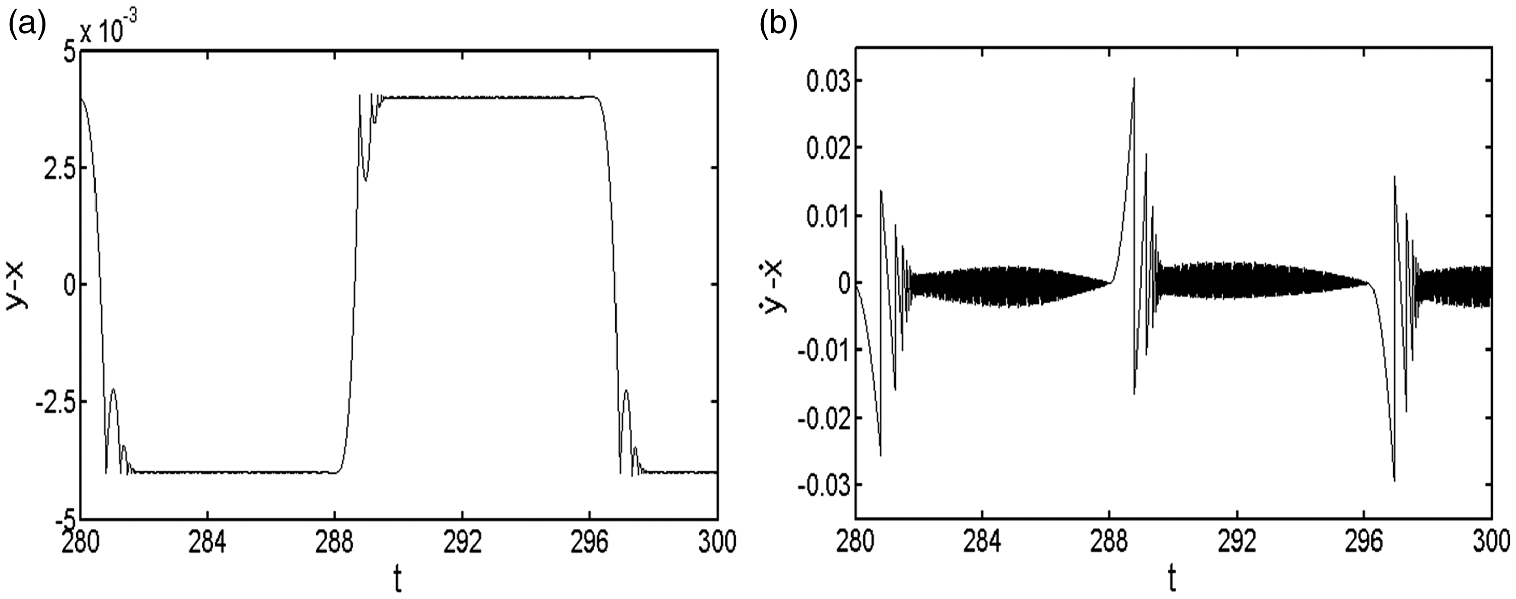
Time-domain diagram with ω = 0.4. (a) Time-domain diagram of relative displacement and (b) time-domain diagram of relative velocity.
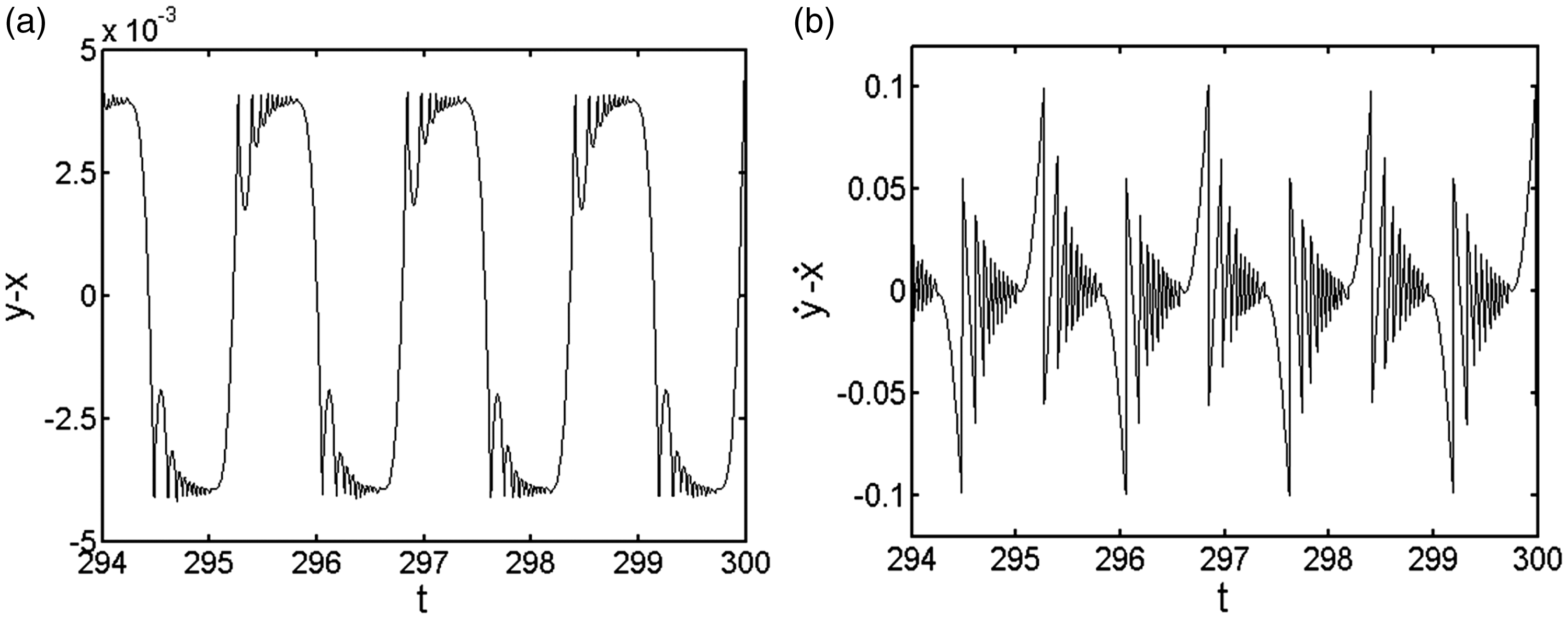
Time-domain diagram with ω = 4. (a) Time-domain diagram of relative displacement and (b) time-domain diagram of relative velocity.
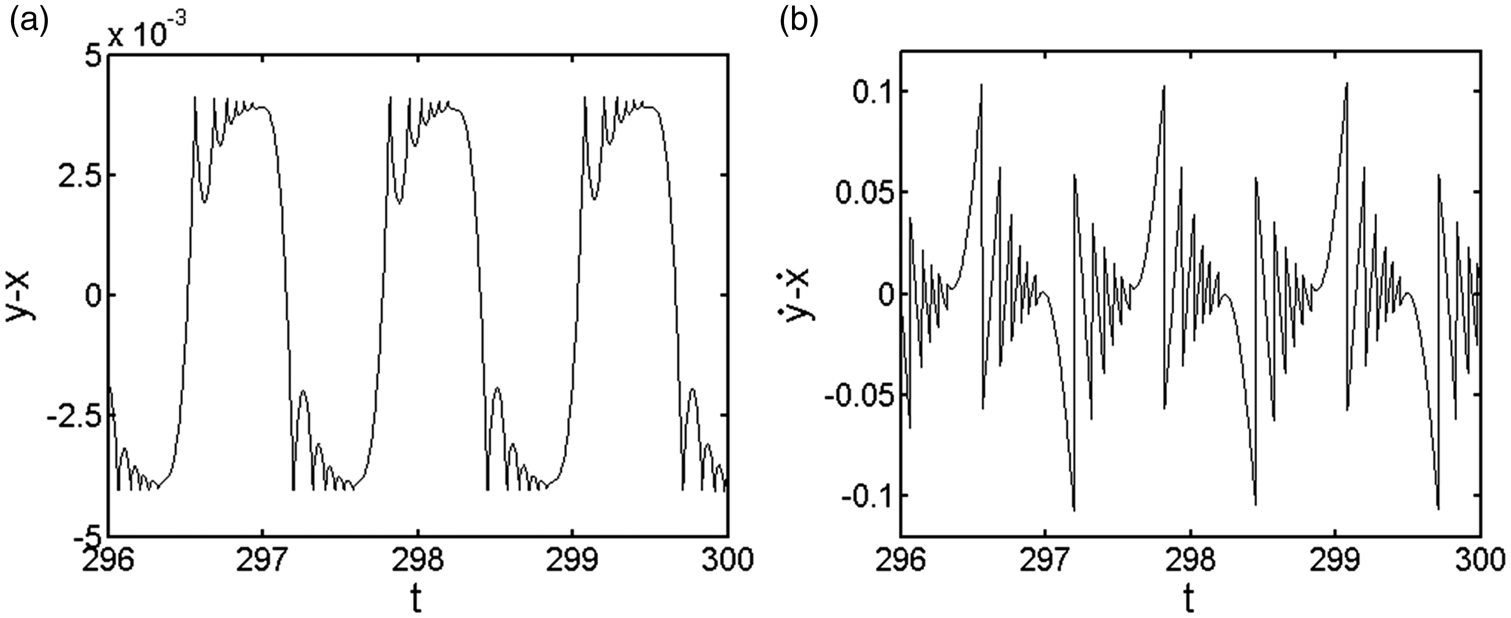
Time-domain diagram with ω = 5. (a) Time-domain diagram of relative displacement and (b) time-domain diagram of relative velocity.
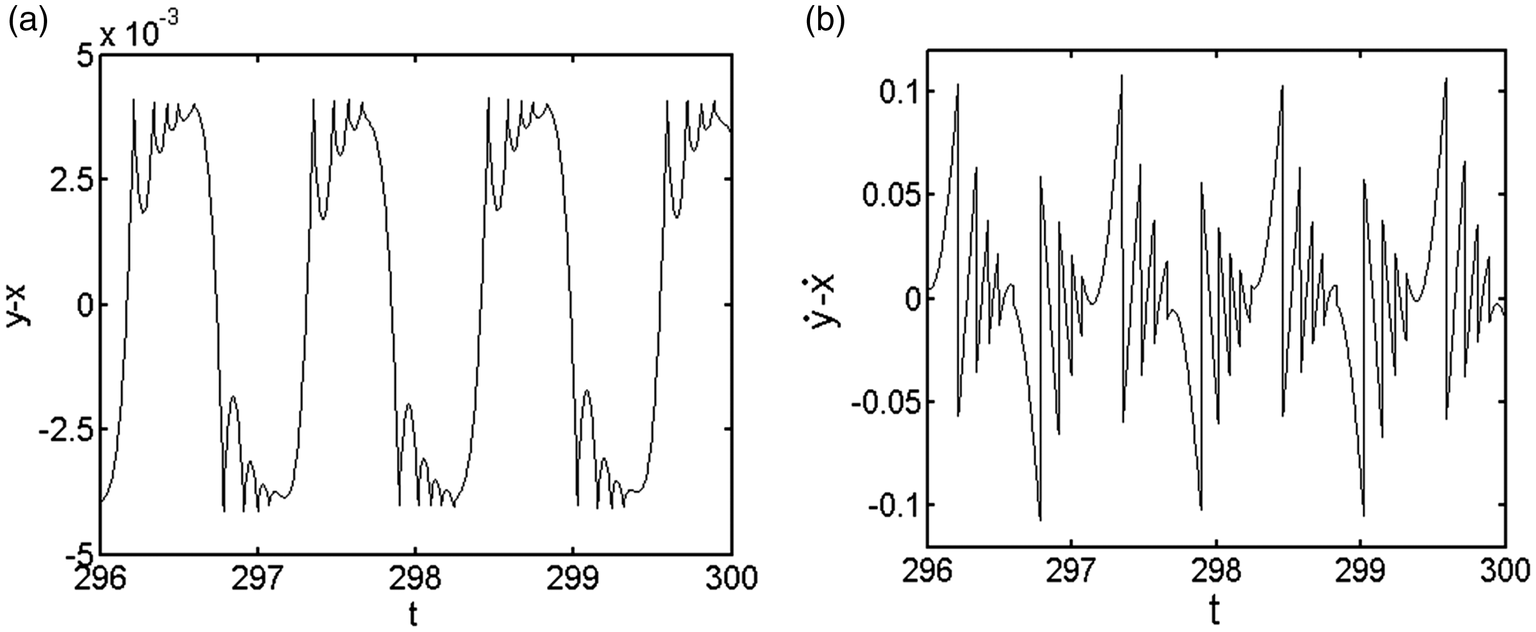
Time-domain diagram with ω = 5.6. (a) Time-domain diagram of relative displacement and (b) time-domain diagram of relative velocity.
Analysis of chattering with clearance δ = 0.05
When the system parameters
It can be observed from Figure 10(a) that there are multiple times, unilateral, continuous collisions between the primary system and the small ball in the impact damper, with the relative displacement being almost a straight line. Besides, the relative velocity (Figure 10(b)) converges to the zero value when the system has a chattering behavior. In Figures 11 and 12, during the process when the primary system and the small ball have five times, continuous, unilateral collisions, its relative velocity converges to the zero value. From Figure 13, after four unilateral, continuous collisions between the primary system and the small ball, they separate. And accordingly, under such parameter condition, there is no chattering behavior in the system. In conclusion, under such clearance condition, the frequency ratio of the system chattering has an interval of ω∈(0,2.5).
Time-domain diagram with ω = 0.4. (a)Time-domain diagram of relative displacement and (b) time-domain diagram of relative velocity.
Time-domain diagram with ω = 2. (a) Time-domain diagram of relative displacement and (b) time-domain diagram of relative velocity.
Time-domain diagram with ω = 2.5. (a)Time-domain diagram of relative displacement and (b) time-domain diagram of relative velocity.
Time-domain diagram with ω = 2.6. (a)Time-domain diagram of relative displacement and (b) time-domain diagram of relative velocity.
Analysis of chattering with clearance δ = 0.5
When the system parameters
Time-domain diagram with ω = 0.4. (a)Time-domain diagram of relative displacement and (b) time-domain diagram of relative velocity.
Time-domain diagram with ω = 1.2. (a) Time-domain diagram of relative displacement and (b) time-domain diagram of relative velocity.
Time-domain diagram with ω = 2. (a) Time-domain diagram of relative displacement and (b) time-domain diagram of relative velocity.
Time-domain diagram with ω = 4. (a) Time-domain diagram of relative displacement and (b) time-domain diagram of relative velocity.
From Figures 6 to 17, the alternation of clearance has an influence on the frequency ratio interval of the system chattering: as the clearance value increases, the frequency ratio interval of the system chattering decreases; if the clearance value exceeds a certain critical value, there is no chattering behavior in the system.
Conclusion
Based on the classical impact damper, this paper establishes the dynamic model of vibro-impact system with unfixed constraints and investigates the effect of the two key parameters, ω and δ on the occurrence conditions of the system chattering behavior by employing numerical simulation method. The conclusion is as below:
Chattering is prone to occur in the low frequency range. As the frequency ratio decreases, the number of unilateral continuous collisions between the primary system and the small ball increases from one collision to multiple collisions, and viscosity behavior appears under the condition of low frequency ratio. Small clearance is prone to chatter. With the increase of the clearance, the frequency ratio range of the chattering in the system decreases. When the clearance exceeds a certain critical value, the system will not experience the chattering behavior.
Footnotes
Declaration of conflicting interests
The author(s) declared no potential conflicts of interest with respect to the research, authorship, and/or publication of this article.
Funding
The author(s) disclosed receipt of the following financial support for the research, authorship, and/or publication of this article: This work was supported by the National Natural Science Foundation of China (grant number 51475308).