
Abstract
For preventing the fragile optical communication devices from malfunction caused by the low-frequency seismic excitation, a novel three-dimensional hybrid isolation platform is proposed in this paper. To isolate the horizontal and vertical vibrations simultaneously, the platform is designed as a combination of a rolling isolation system and four three-parameter isolators with active damping. By deriving the governing equations of the three-parameter isolators and the profile of the concave rolling surface, the dynamic model of the whole platform is constructed. Numerical results indicate that the isolation platform has an effective suppression of the horizontal and vertical vibrations. To verify the isolation performance of the hybrid isolation platform, an experiment is conducted in the targeting frequency range. Compared to the amplification factor of 6.2 dB of the three-parameter isolator, the test results exhibit that the hybrid isolation shows no amplification effect in the vertical direction, and the root mean square value of acceleration responses can be decreased by more than 65% in the frequency range of 0–32 Hz. In the horizontal direction, the reduction of the root mean square value of acceleration responses is up to 85% in the same frequency range.
Keywords
Introduction
With the increasing demand of new generation communication technology, high-speed data transmission devices have been developed. As a critical part, the optical switch is highly sensitive to vibration and cannot operate properly even under tiny disturbances.1,2 In general, the switch works with other equipment in the cabinet, thus the vibrational energy caused by ground excitation transmitted to the switch would be amplified due to the flexibility of the cabinet structure. In order to protect the optical switch from the vibration disturbances, an effective vibration isolation solution is needed urgently.
For the isolation of low-frequency vibration, the conventional isolators, such as rubber isolators, wire rope isolators, and air spring isolators,3–6 have a relatively high isolation cutoff frequency. Furthermore, with the limit of the installation space in the cabinet, they cannot guarantee an ideal performance. Although the isolators of high-static–low-dynamic-stiffness have better isolation performance in the low-frequency range, they are not commonly used in practical applications due to their limited loading capacity and stroke.7–9 In the field of antiquake engineering, the rolling isolation systems can protect superstructure from ground excitation by decoupling the horizontal motion of floors and equipment, and these isolation systems are extremely effective when their displacement limits are not exceeded. The rolling devices, such as cylindrical rollers and rolling balls, are placed at the bottom of isolated objects to reduce the transmission of horizontal force.10,11 Nacamuli and Sinclair reviewed the base isolation systems developed by WorkSafe® Technologies. The maximum lateral displacement of the ISO-BASE system is 8 in.12,13 Cui 14 investigated an isolation system to protect acceleration-sensitive equipment, where solid rubber and polyurethane balls instead of steel balls were used. Harvey built a nonlinear dynamic model of the isolation system using the Lagrange equations and demonstrated isolation characteristics through numerical simulation and experiment. Moreover, the double rolling isolation systems were proposed to increase the limit of horizontal displacement.15–17
It is worthy of noting that the rolling isolation systems can isolate the horizontal vibration only, but the vibration-sensitive optical device is highly sensitive to three-axis vibrations and its bearable maximum acceleration is 0.2 g. Therefore, it is important to isolate the three-axis vibrations simultaneously.
In the vertical direction, in order to suppress the peak response at the resonance, viscous damping is commonly used, but this leads to degraded isolation performance at high frequencies. As one kind of the viscous damping, the fluid damping consumes energy through the internal friction in the process of viscous fluid flow. Also, it has wide damping force and easy to implement in structure. However, to improve the isolation performance in the high-frequency range, the three-parameter isolator is adopted because of its high roll-off rate at high frequencies compared to the two-parameter isolator.
Isolators of fluid damping are widely used in the space field and the typical application is the reaction wheel isolation in the Hubble Space Telescope.18,19 Wang et al. 20 investigated the damping and stiffness characteristics of a fluid-bellow isolator for micro-vibration isolation and built an equivalent three-parameter model. Huang et al.21,22 proposed an isolator fabricated with formed bellows, whose amplification factor is about 7 dB and resonance frequency is about 17 Hz with the loaded mass of 15 kg. Aside from the aforementioned passive isolators, some passive–active hybrid isolators were also studied.23–25 The hybrid isolators have the advantages of both the passive and active isolation. Davis designed a hybrid AD strut, which combines the isolator of fluid damping and electromagnetic actuators and can be used to suppress micro-vibration of high performance optical payloads. The isolation performance in microgravity environment can achieve 10–30 dB attenuation of acceleration on the band of 0.1–300 Hz. 26 Lee et al.27,28 investigated a hybrid isolator of bellows and viscous fluid; the experimental results showed that the passive isolator can achieve a high roll-off rate of about −40 dB/dec, and the amplification at the resonance frequency is about 6.5 dB.
In this paper, to meet the isolation requirements of sensitive devices at low frequencies, a three-axis vibration isolation platform was proposed to be placed at the bottom of the device. In the platform, four three-parameter isolators are used in combination with electromagnetic actuators to reduce vertical vibration and a rolling isolation system is used to reduce horizontal vibration. The discussion is organized into four sections. In the next section, the dynamic model of the hybrid isolation system is established and the isolation performance is evaluated. Experimental results of the isolation performance are given in “Experiment” section and conclusions are summarized in the final section.
Dynamic model and numerical simulation
The schematic diagram of the hybrid vibration isolation platform and its application is shown in Figure 1, where the isolation platform is mounted between the middle layer of the cabinet and the bottom of the vibration-sensitive optical switch. The platform is applied to isolate the transmitted vibration that is induced by the ground excitation in the vertical and horizontal directions. In the platform, a rolling isolation system is used to reduce horizontal vibration and four three-parameter isolators in combination with two electromagnetic actuators are used to reduce vertical vibration, as shown in Figure 1(b) and (c).
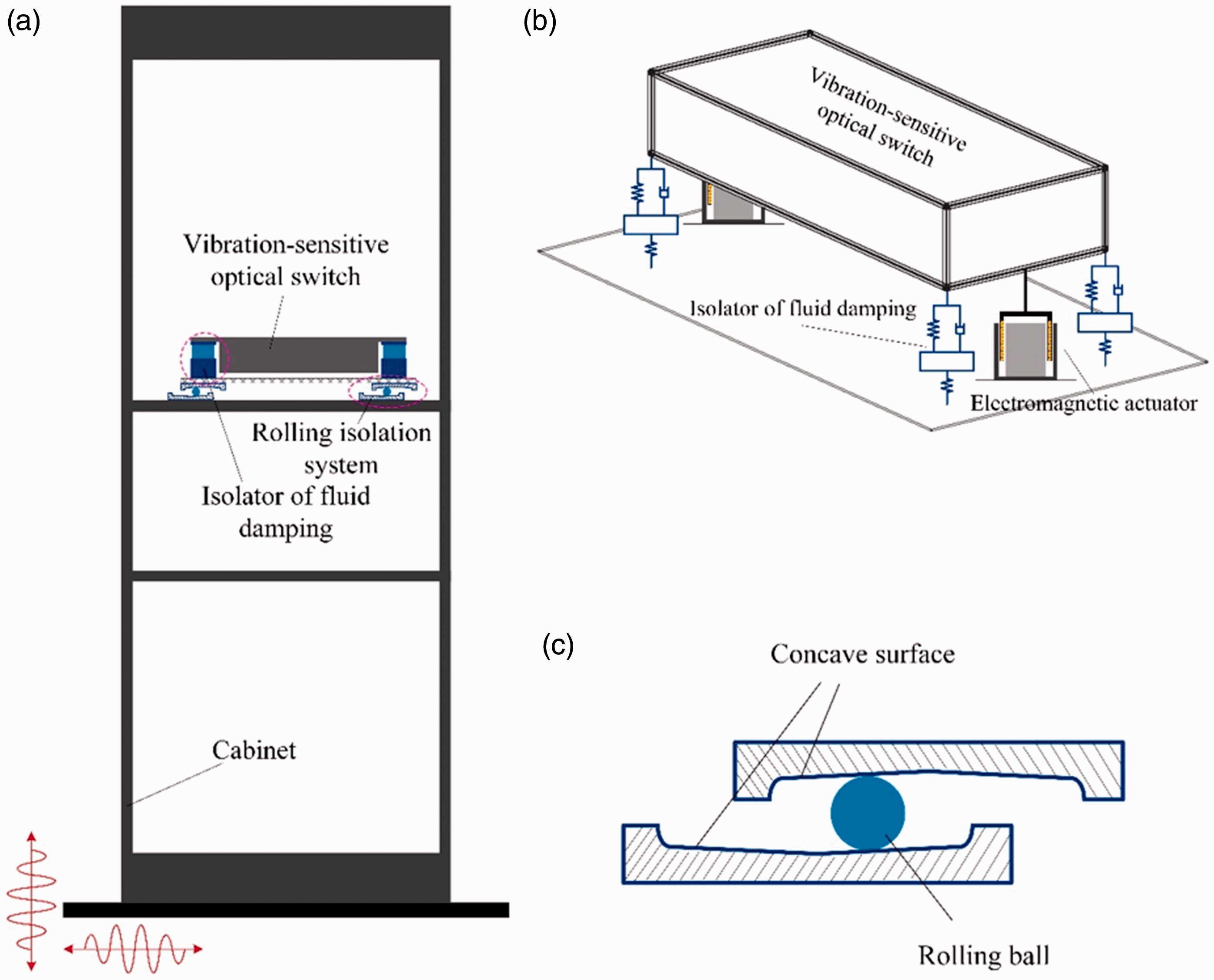
Schematic of the isolation system. (a) Schematic view of the application of the vibration isolation platform, (b) schematic of the vertical isolation, and (c) schematic of the horizontal isolation.
In the following sections, the vibration model in the vertical and horizontal directions is established. In the vertical direction, the influence of the natural vibration of the cabinet is ignored due to the high rigidity of the cabinet. However, vibration of the cabinet in the horizontal direction is considered.
The hybrid isolator
The passive isolator of fluid damping mainly consists of three diaphragm bellows, one rigid cylinder, and two connecting ends. Structure and photo of the fabricated isolator is given in Figure 2. Three bellows are used to provide the stiffness of the three-parameter isolator. The upper and middle bellows also act as fluid chambers and they are connected through an orifice so that damping is induced when the fluid passes from one chamber to the other. The viscous damping can be adjusted by changing the diameter of the orifice.
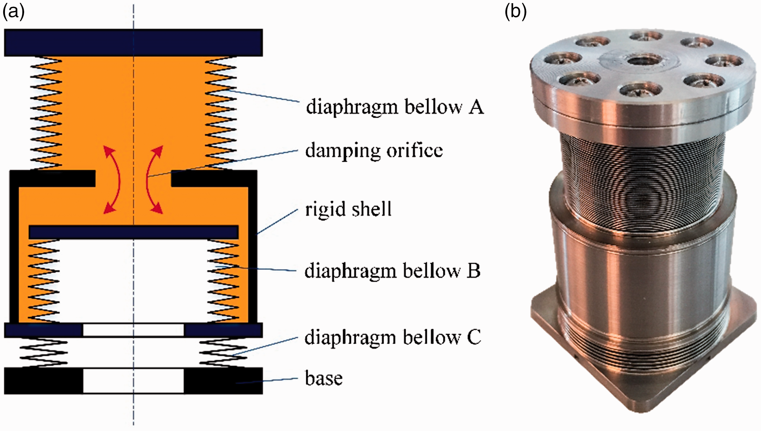
The isolator of fluid damping. (a) Structure and (b) photo.
Four three-parameter isolators are used in combination with two electromagnetic actuators to reduce the vertical vibration, as illustrated in Figure 1(b). Accordingly, only the vertical vibration is considered. Note that the vertical stiffness of the cabinet is large enough that the cabinet can be regarded as a rigid body in the vertical direction. Therefore, vibration of the symmetric platform can be represented by a 2-DOF system, as shown in Figure 3, where the isolator is represented by a three-parameter model and the actuator is placed in parallel with the isolator,
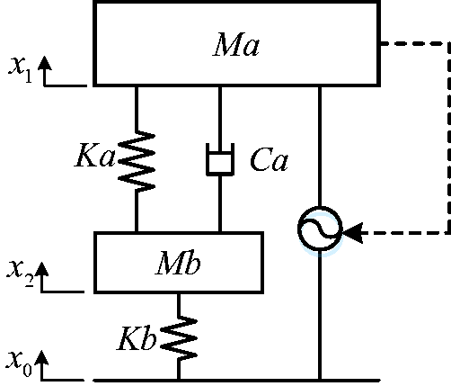
The hybrid three-parameter model.
The dynamic differential equations of this system can be expressed as follows

For the passive isolation, the transfer function between

For the hybrid isolation, in which the active force

The transmissibility curves corresponding to equations (2) and (3) are shown in Figure 4. Ma is 3 kg and Mb is 0.3 kg. The chosen stiffness for the bellows A and B are 800 N/m and for the bellow C is 2.8e4 N/m, which result in cutoff frequency at about 15 Hz. In addition, the bellow C is used to attenuate high-frequency vibration. The damping coefficient Ca is determined mainly by the size of the damping orifice. The initial/optimal value of Ca is calculated through simulation, but the final value is determined by experimental tests. The comparison of different damping orifices is implemented and a superior parameter of damping orifice is selected finally.
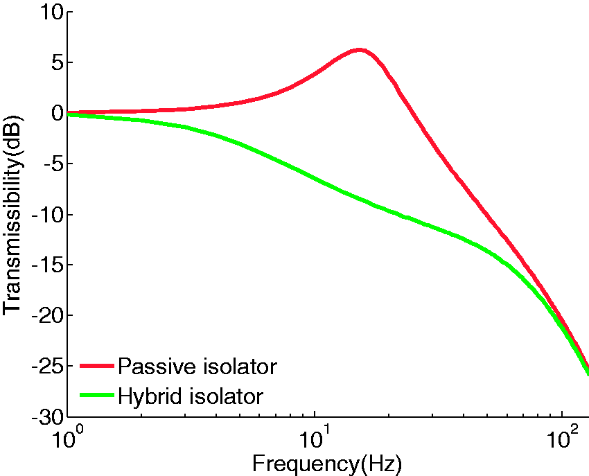
Transmissibility of the passive/hybrid isolator.
As can be seen, the resonance frequency of the passive isolation is about 15 Hz and the amplification factor is about 6 dB, but the attenuation region of the hybrid isolation covers nearly the whole frequency; moreover, the maximum attenuation rate of the passive and the hybrid isolation is about −35 dB/dec.
The rolling isolation system
The vibration model in the horizontal direction is shown in Figure 5. As can be seen, the model of the cabinet is represented by a 3-DOF mass–spring–damping system, where m1, m2, and m3 are the equivalent masses; k1, k2, and k3 are the equivalent stiffness; c1, c2, and c3 are the equivalent damping coefficients; xg, xh1, xh2, and xh3 are, respectively, the displacements of the ground and the three masses.
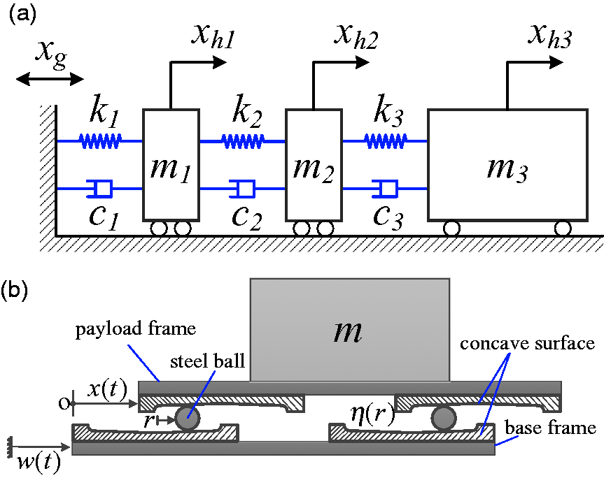
Vibration model in the horizontal direction. (a) The model of the cabinet and (b) the model of the rolling isolation platform.
The dynamic equations can be expressed as follows
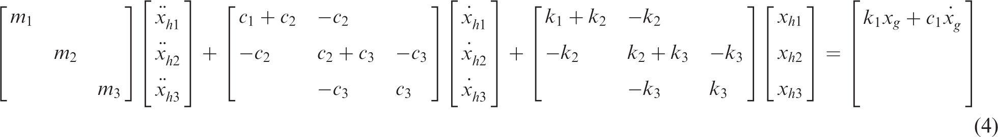
The rolling isolation system consists of axisymmetric concave rolling surfaces, rolling balls, base and payload frames, as shown in Figure 5(b), where
Suppose the rolling balls move unanimously in each direction, the dynamic model of the rolling isolation system can be simplified and represented by an oscillating system of single DOF. The natural frequency of the vertical isolation system is 15 Hz (Figure 4) and the isolation frequency of the rolling isolation system in the horizontal direction is only 1 Hz or so. Moreover, the vertical excitation caused by the rolling isolation system cannot excite the elastic mode of the vertical isolation system. Therefore, the coupling between the horizontal and the vertical motion can be neglected. For the dynamic model of the rolling isolation system, due to the shallow concave rolling surface, the vertical component of kinetic energy can be neglected and the kinetic energy of the system can be expressed as

Assume that the rolling ball is in the center of the concave surface initially, the relative displacement is thus

In light of the Lagrange’s equation, the equation of motion is given by


The simplified dynamic equation is given as follows

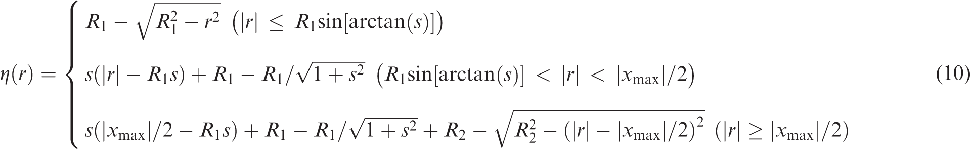
The generatrix of the concave surface usually consists of three segments. The first segment is an arc where the rolling ball and the surface contact tangentially; the second is a straight line of a fixed slope; and the third is the edge of the concave surface, which restricts the movement of the rolling ball. Moreover, the radius of the surface (the projection of the generatrix) is determined by the maximum relative displacement of the payload, i.e.
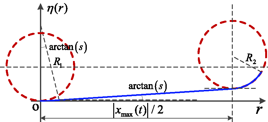
Three segments.
According to equation (9), the absolute acceleration of the payload can be expressed as

Therefore, the concave surface can be determined in terms of the allowable maximum acceleration of the payload. The slope of 0.05 is chosen to verify the validity of the dynamic model and the performance of the rolling isolation system, which can be simulated according to equations (9) to (12). The obtained generatrix of the concave surface is illustrated in Figure 7.
The generatrix of the concave surface.
The resonance frequency of the passive isolation is computed from the free oscillation of the rolling isolation system. Let the initial displacement
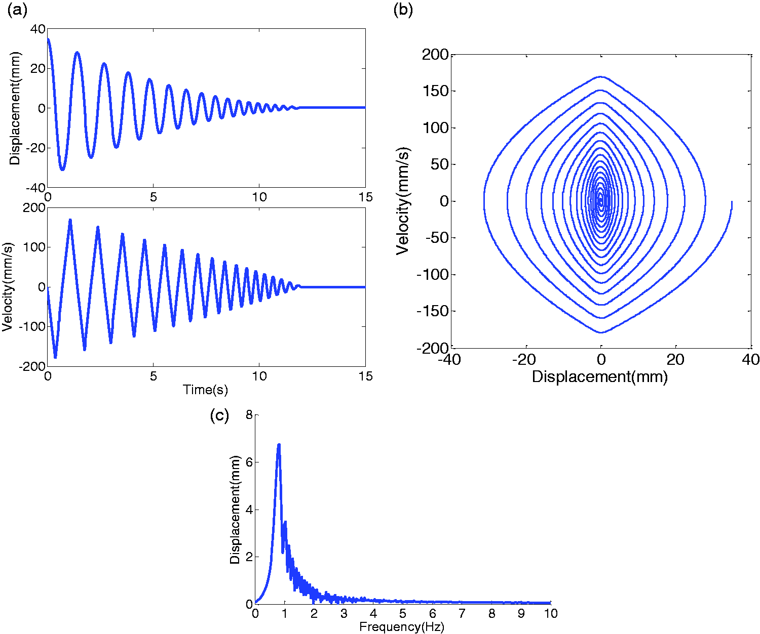
Responses of the free oscillation. (a) Time domain, (b) phase projection, and (c) frequency domain.
The spectrum of the displacement response is shown in Figure 8(c). It can be seen that there are peaks appearing in the frequency domain and this is due to the rolling isolation system being a nonlinear system according to equation (9). In Figure 8(a), the period of the first oscillation is 1.41 s and the subsequent oscillation periods decrease. The peak-to-peak periods for the second through 16th cycles are 1.28, 1.13, 1.02, 0.90, 0.82, 0.72, 0.65, 0.59, 0.52, 0.47, 0.44, 0.40, 0.40, 0.40, 0.40 s, respectively. It can be seen that the frequency increases with the decrease of the displacement of the payload. The rolling isolation system does not have a fixed oscillation frequency, so the dynamic behavior of the isolated payload is not totally dependent on the frequency spectrum of the excitation.
When a horizontal impulse excitation is applied to the base of the cabinet, the whole system will vibrate but the responses will decay to zero due to the structural damping and friction. The maximum acceleration amplitude of the impulse excitation is about 0.2 g and the acceleration responses of the payload is given in Figure 9, where the red (dark) line is the response of
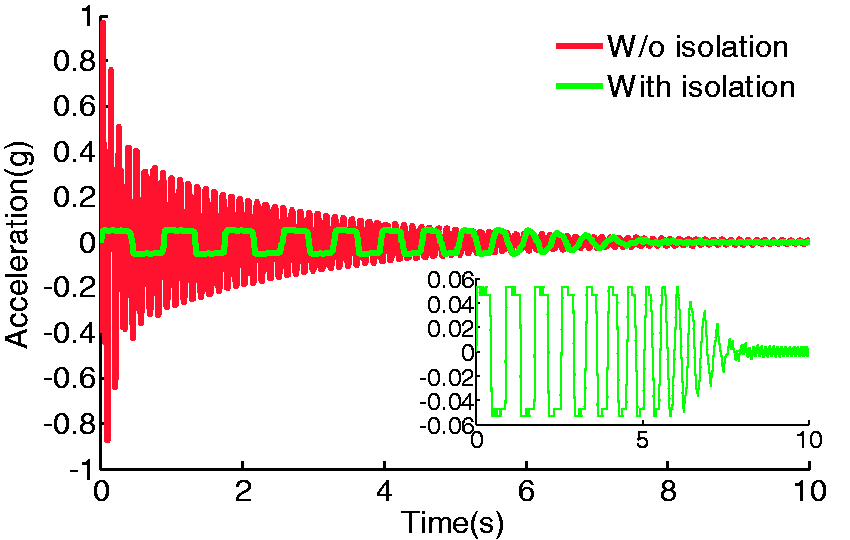
Acceleration responses to the horizontal impulse excitation.
Experiment
Isolation in the vertical direction
Experiments were conducted to verify the isolation performance of the hybrid isolation platform. The experimental system, as shown in Figure 10, includes a vibration shaker, a payload (its dimension and mass are 294 mm × 103 mm × 54 mm and 3 kg, respectively), a cabinet (its dimension is 600 mm × 300 mm × 2000 mm), three accelerometers (charge type, its sensitivity is 4 pc/(m/s2)) and one signal conditioner, two electromagnetic actuators and a power amplifier, a dynamic signal analysis system (LMS SCADAS), and the hybrid isolation platform. The cabinet was placed on the table of the shaker and an accelerometer was mounted at the bottom of the cabinet to measure its vertical vibration. The vertical vibration responses of the payload were measured by two accelerometers, one of which was used as the feedback transducer to the actuators.
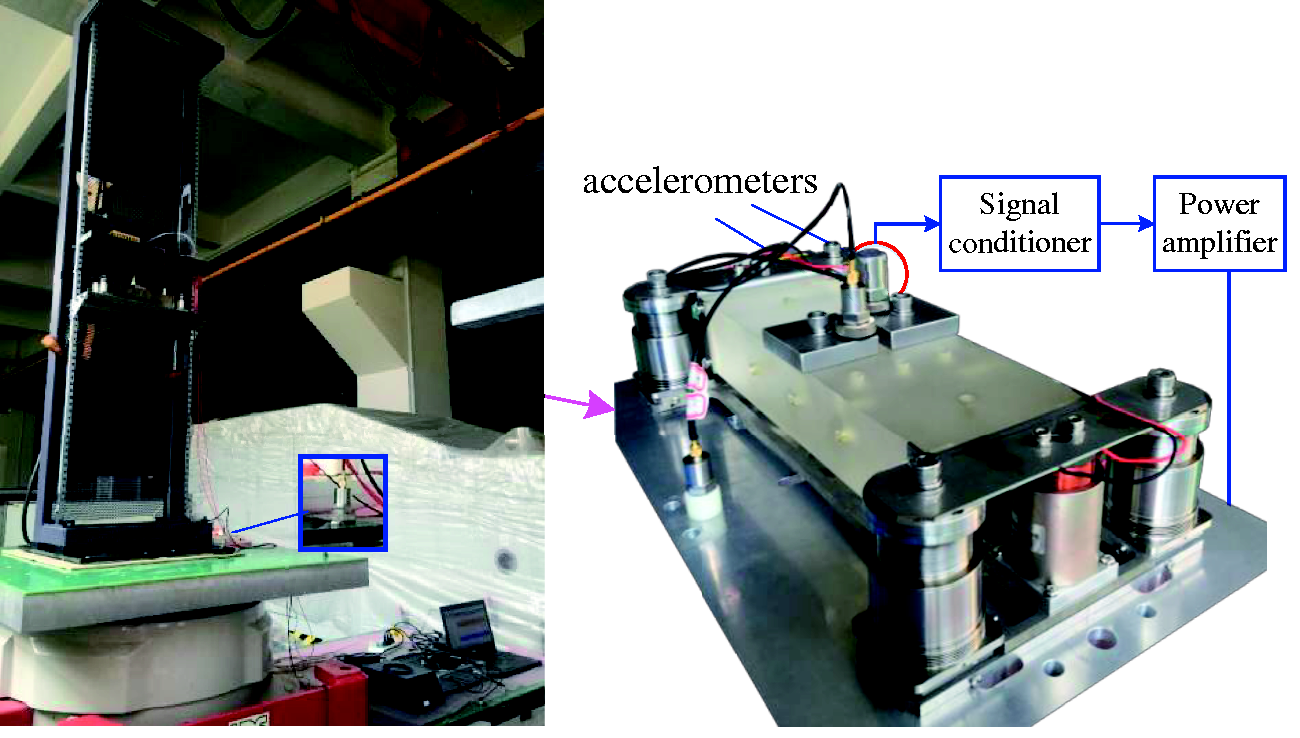
Experimental system for the vertical isolation test.
The parameters of the experimental passive isolator in “Isolation in the vertical direction” section are the same as those of the isolator in “The hybrid isolator” section, but it should be mentioned that the damping Ca of the passive isolator can be tuned by changing the diameter of the orifice. A group of orifices were tested and the optimal damping coefficient was chosen for the isolator.
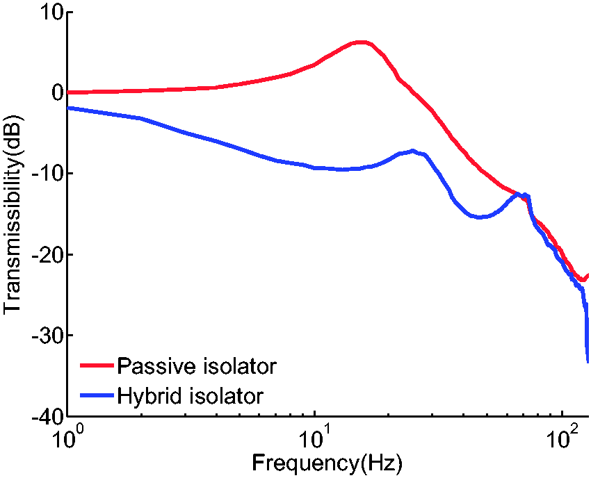
The acceleration transmissibility from the bottom of the cabinet to the payload was measured and the corresponding curves are plotted in Figure 11. The frequency range of the random excitation is 0–128 Hz, and the sampling rate is 256. It can be seen that the resonance frequency of the passive isolation is about 15 Hz and the amplification factor is 6.2 dB. The passive isolation has an attenuation rate of about −35 dB/dec over 20 Hz and the attenuation is more than 20 dB at frequencies greater than 100 Hz. In comparison, the acceleration transmissibility of the hybrid isolation is suppressed substantially in the frequency range of 0–70 Hz and it is less than 0 dB over 1 Hz.
Transmissibility curves in the vertical direction.
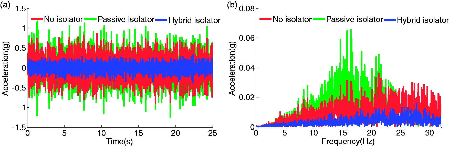
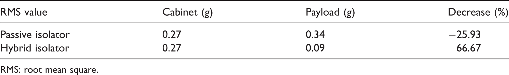
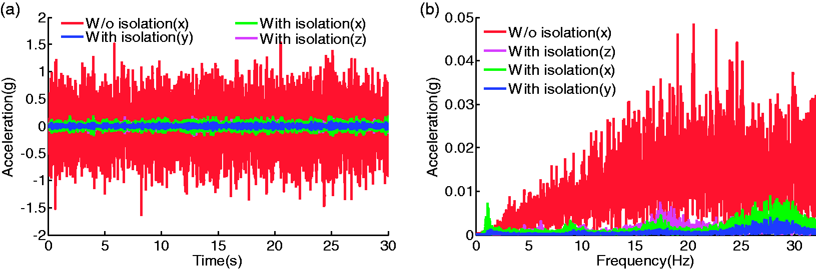
The acceleration responses of the cabinet and the payload are shown in Figure 12, which were measured under the random excitation in the frequency range of 0–32 Hz. The root mean square (RMS) values of the responses are listed in Table 1. As can be seen from Figure 12 and Table 1, the RMS value of the bottom of the cabinet is 0.27 g, and the RMS value of the payload with passive isolation is 0.34 g, which is increased by about 26%. This demonstrated that the passive isolators have no attenuation in the test frequency range because there is an amplification region between 8 and 20 Hz. However, the RMS value of the hybrid isolation is 0.09 g and the attenuation is about 67%, as compared with the passive isolation.
Isolation performance under random excitation (0–32 Hz) in the vertical direction. (a) Time domain and (b) frequency domain.
The RMS values before and after isolation under random excitation (0–32 Hz).
RMS: root mean square.
Isolation in the horizontal direction
The performance of isolation in the horizontal direction was also experimentally tested. In the experiment, vibration was generated by the shaker, as shown in Figure 13. An accelerometer was mounted at the bottom of the cabinet and the measured horizontal vibration was used as the reference response. Three accelerometers were mounted at the payload to measure the three-axis vibrations, respectively. The measured acceleration responses were compared with the reference response and the isolation performance was evaluated.
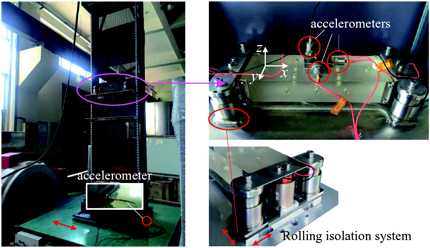
Experimental system for the horizontal isolation test.
Figure 14 shows the results of isolation in the horizontal direction, which were measured acceleration responses to the random excitation in the frequency range of 0–32 Hz. As shown in Figure 14, the rolling isolation system is excellent in isolating the vibration transmitted from the bottom of the cabinet and has no influence on vibrations in other directions. The RMS values of the acceleration responses were evaluated, which are 0.45 and 0.05 g, respectively. Accordingly, vibration attenuation of the horizontal isolation system is about 88%.
Isolation performance under random excitation (0–32 Hz) in the horizontal direction. (a) Time domain and (b) frequency domain.
Furthermore, the horizontal isolation performance under low-frequency excitation was verified as well. Excitation in the frequency range of 1–3 Hz was generated by the shaker. As illustrated in Figure 15, the horizontal isolation system has a noticeable performance and the maximum accelerations of the bottom of the cabinet and the payload are 0.83 and 0.17 g, respectively, indicating that the acceleration is reduced by about 80% after isolation. Moreover, the maximum accelerations in the orthogonal directions are 0.03 and 0.04 g, which demonstrate that the isolation system has least coupling in orthogonal directions (X, Y, and Z directions).
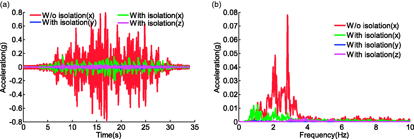
Isolation performance under random excitation in the low-frequency range. (a) Time domain and (b) frequency domain.
Conclusion
A low-frequency hybrid isolation platform for vibration-sensitive optical devices is presented, evaluated, and tested. Four three-parameter isolators are used in combination with electromagnetic actuators to reduce vertical vibration and a rolling isolation system is used to reduce horizontal vibration. Based on the derivation of the mechanical parameters of the three-parameter isolator and the profile of concave rolling surface, the dynamic equation of the hybrid isolation platform is established which considers both the vertical and horizontal vibrations of the system. In the vertical direction, to eliminate the amplification effect of the three-parameter isolator and broaden the isolation region, the active damping is supplemented to increase the absorption of the vibrational energy. Numerical results indicate that the hybrid isolation platform can significantly suppress the vibration in both the vertical and horizontal directions. As a verification, an experiment is conducted to test the isolation performance. According to the experimental data, in the vertical direction, the passive isolator has an amplification factor of 6.2 dB; as an improvement, the transmissibility of the hybrid isolator is below 0 dB over the test frequency range. Also, when the system is subject to random excitation, the hybrid isolator can provide a reduction up to 65% of the RMS value of the acceleration responses in the frequency range of 0–32 Hz. Meanwhile, in the horizontal direction, the RMS value of acceleration responses is reduced by more than 85%. Moreover, even within the low-frequency range (1–3 Hz), an 80% reduction of the RMS value can be achieved.
Footnotes
Declaration of conflicting interests
The author(s) declared no potential conflicts of interest with respect to the research, authorship, and/or publication of this article.
Funding
The author(s) disclosed receipt of the following financial support for the research, authorship, and/or publication of this article: This research work was partly support by National Natural Science Foundation of China (Grant No. 11672180).