
Abstract
A damage assessment problem can be stated as a constraint satisfaction problem utilizing the translational and rotational displacements of a structure as measurements. By this means, usual numerical models are no longer required for a damage assessment, which considerably simplifies the solution process. In order to avoid the use of rotational displacements that are difficult to measure in practice, an improved analytical redundancy reduction method has been developed in which rotational displacements are replaced by translational ones. Moreover, some constraint equation positions in the decomposition of a static equilibrium matrix are exchanged according to their association with pre-assumed damaged elements. Then damage is located according to the changes in the relevant constraints of specific elements or substructures. Besides, the deviation increments of improved analytical redundancy reduction can embody the stiffness changes of the damaged elements. The proposed improved analytical redundancy reduction method was validated using both numerical and experimental steel box beams under static loads. The damage assessment results demonstrate the superiority of the improved analytical redundancy reduction method over the constraint satisfaction problem and analytical redundancy reduction methods.
Keywords
Introduction
Structural health monitoring and condition evaluation of civil structures such as buildings, bridges and dams are essential for structural safety.1–3 Damage assessment based on structural measurement data is the core of a health monitoring procedure, whose purpose is to figure out whether a structure is damaged and where the damage is. Meanwhile, damage assessment or fault diagnosis is often carried out using different optimization algorithms4,5 or machine learning approaches. 6
In general, static and dynamic measurements of a structure are adopted as objective responses for damage assessment.7–12 Static testing can straightly reflect the current stiffness or resistance ability of the structure and thus is often used for the evaluation of bridges. Displacements or deflections are first options, and a model updating procedure or parametric study 7 can be employed for assessment. Meanwhile, strains measured by a spatially distributed long-gauge strain sensing scheme are also effective for identifying damage of bridge structures. 8 In case static testing is difficult to perform or test expenses are most concerned, vibration-based damage assessment can be used as an alternative. Modal properties such as frequencies, mode shapes and frequency response functions are most commonly used to construct damage indices.9,10 Time-history properties such as wavelet functions play an important role as well in damage assessment 11 since damage features can be directly extracted from the decompositions of response signals. Furthermore, multi-scale structural damage identification using both static and dynamic measurements is an alternative option with the aid of multi-objective optimization algorithms. 12 However, it should be noted that most damage assessment methods require numerical models (e.g. Finite element (FE) models) for computing the objective static or dynamic responses, especially when model updating strategies are implemented. This procedure is generally time-consuming and takes immerse computational expense for complex structures. Moreover, the topic of model errors can never be avoided, and ill-conditioned updating problems often happen. Due to these drawbacks, non-model based damage assessment techniques could offer a solution.
Constraint satisfaction problems (CSPs) are actually within the mathematical framework, and such problems are assigned with a set of objects that must satisfy a number of constraints over a set of variables. 13 A damage assessment problem can be transformed into a CSP established on the structural equation of static equilibrium.14,15 By this means, structural numerical models are no longer necessary since damage is evaluated on some mathematical expressions. The state change of a reinforced concrete beam was embodied by the inflection point at the load-deflection curve. 15 Meanwhile, in order to avoid the utilization of rotational displacements, the theory of analytical redundancy reduction (ARR) was adopted for solution simplification. But the ARR method is unable to locate the damage. Due to it, this study attempts to develop an improved ARR (IARR) method that can achieve damage location. A structure is divided into several substructures whose constraints are formed by decomposing the static equilibrium matrix into a set of equations after position adjustment. For its applications to real-world structures, deviation analysis of IARRs is further adopted for better prediction of constraint changes. The feasibility of the proposed method has been verified against both numerical and experimental beams under the comparisons with traditional CSP and ARR methods.
Constraint satisfaction problems
Definition of a CSP
The CSP theory is useful in the realm of artificial intelligence, and a CSP may have different definitions and expression forms. A CSP for damage assessment can be defined by a triple set combination of
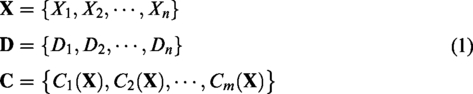

To be specific, structural damage is defined as the stiffness reduction of each element and
CSP for static analysis
Static load testing is a straight and effective way to evaluate the current state (load-bearing capacity) of a structure. Therefore, for the purpose of damage assessment, the structure can be divided into substructures each of which is assigned with several constraints. Then according to the inconsistence of specific substructures, the damage can be located. This procedure is useful and easy to implement for beam-type structures such as a continuous beam bridge.
14
The structural constraint equations are established based on the equation of static equilibrium written as

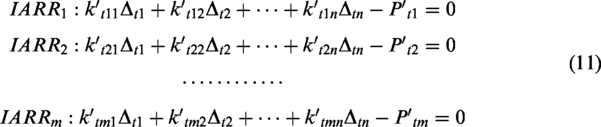
Equation (3) can be further decomposed into equilibrium equations each of which represents a constraint corresponding to an element or a substructure
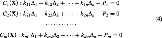
Theoretically, constraints related to undamaged elements/substructures remain zero. On the contrary, their values will be unequal to zero due to the loss of local stiffness.
Improved analytical redundancy reduction
Definition of ARR
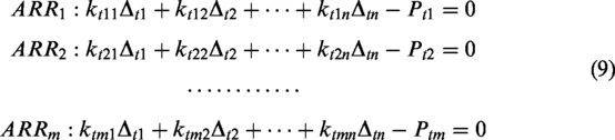
Practically, rotational displacements required for the solution of a CSP are difficult to measure, which highly limits its applications to engineering problems. Instead of real measurements, numerical rotational displacements can be alternatively obtained by solving equation (3) with known translational displacements. However, this alternative scheme might induce some theoretical conflicts for the subsequent solution of constraints’ values. To overcome this drawback, ARRs can be used to establish the relationships among constraints containing only observed variables
15

If the observations satisfy the specific constraints (r = 0), then the ARRs are satisfied. The changes of ARRs embody the damage. For a CSP, the merit of the involvement of ARRs lies in the absence of measuring rotational displacements, which enhances the practicability of the CSP procedure.
ARR for static analysis
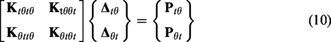
Suppose that the translational and rotational degrees of freedom (DOFs) are already separated, then equation (3) is rewritten in the form of block matrices

In order to eliminate the rotational variables, they can be expressed by the translational variables through solving the second equation of equation (6)

Then equation (7) is introduced into

Equation (8) is further decomposed into a set of equations each of which corresponds to a constraint. Here for simplicity, the rotational external force
The ARR method could identify the external loads when the overall stiffness properties of a reinforced concrete beam changed under vertical concentrated loads.
15
The advantage lied in the damage of the entire beam could easily be detected according to the changes of the ARR values. However, it is incapable of locating the damage since the stiffness of all substructures is mixed in
Improved ARR
Aiming at the purpose of damage location, improvement on the above ARR method was proposed. Firstly a structure is divided into some substructures, and damaged substructures are assumed. Then equations in equation (6b) related to the damaged substructures are moved to equation (6a). And an equal number of equations in equation (6a) related to the undamaged substructures (adjacent to the damaged ones) are moved to equation (6b). After that, equation (6) is rewritten as
where
The IARR can establish constraints for every assumed damaged substructure. When real damage occurs in the assumed damaged substructures, the relevant constraints become inconsistent, but the other constraints remain zero. On the other hand, if the damage assumption is wrong, then all the constraints will be inconsistent. By this means, the damage assessment procedure is performed in an exclusive way.
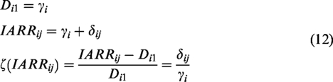
Deviation analysis of IARR
The IARR-based damage assessment requires the measurements from the undamaged structure. However, due to the difference between theoretical model and the real-world structure, constraints may not be zero at the beginning resulting in misjudgement that the structure is already damaged. Meanwhile, different constraints show different sensitivities to the damage. Therefore for practical cases, damage can’t be assessed simply by the changes of constraints’ values. Besides, uncertainties between adjacent load steps could lead to greater effects on constraints than the damage affection. Therefore, this study proposes deviation analysis of IARRs (ƐIARRs) at a certain load step
Numerical validation
Simulation of beam model
A numerical simply supported box beam was first adopted to validate the proposed method. The geometric dimensions and the external loads are illustrated in Figure 1. The elastic modulus was E = 202 GPa, and the density was 7850 kg/m3. The entire beam was divided into six Euler-Bernoulli beam elements, and every element has one translational and one rotational displacement at each node.
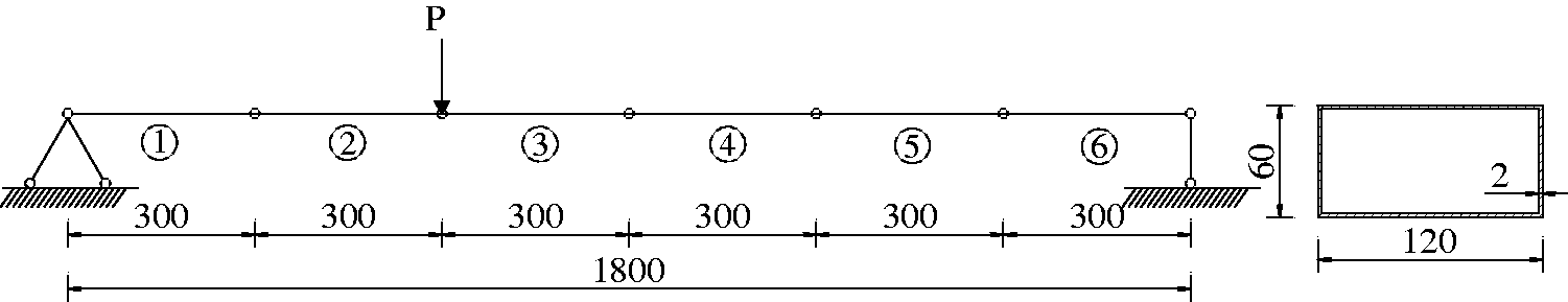
Schematic diagram of the numerical box beam (mm).
A concentrated load was applied at the node shared by elements 2 and 3 with an increment of 1 kN. Damage was simulated by reducing E of element 4 that was introduced at the 4th load step of P = 4 kN. Then the load was held, and E of element 4 decreased by 3%, 5%, 8% and 10%, giving four different scenarios.
Establishment of the static constraints
The constraints of a CSP for this beam were formed according to the element division. Totally 12 constraints C2–C14 were established (Figure 2). Since C1 and C13 corresponding to the deflections at the support ends were always zero, they were not necessarily included in the analysis. The constraint expressions are given below as an example
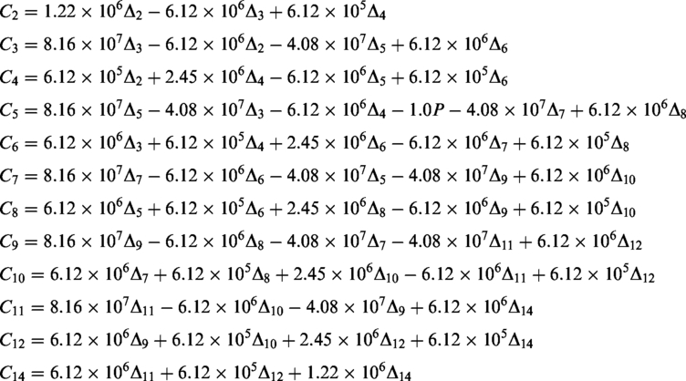
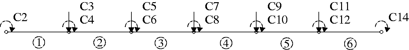
Constraint assignment of the numerical box beam.
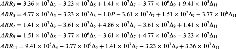
The classic ARR method was secondly performed where the rotational constraints of C2, C4, C6, C8, C10, C12 and C14 were selected for obtaining the relationships between the rotations and deflections. Then such relationships were introduced into the left constraints of C3, C5, C7, C9 and C11 in order to construct ARR3, ARR5, ARR7, ARR9 and ARR11
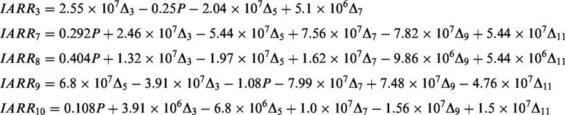
Thirdly, the proposed IARR method was also implemented for comparison. At this moment, rotational constraints C8 and C10 related to the damaged element 4 were moved to equation (6a) in exchange for C5 and C11 belonging to elements 3 and 5. After that, instead of C2–C14 in ARR, a new group of constraint equations, C2, C4, C5, C6, C11, C12 and C14, was used to obtain the relationships between the rotations and deflections. Then such relationships were introduced into the left constraints of C3, C7, C8, C9 and C10 to eliminate the rotational variables. Hence, new constraints based on IARR method were constructed as follows
Damage assessment results
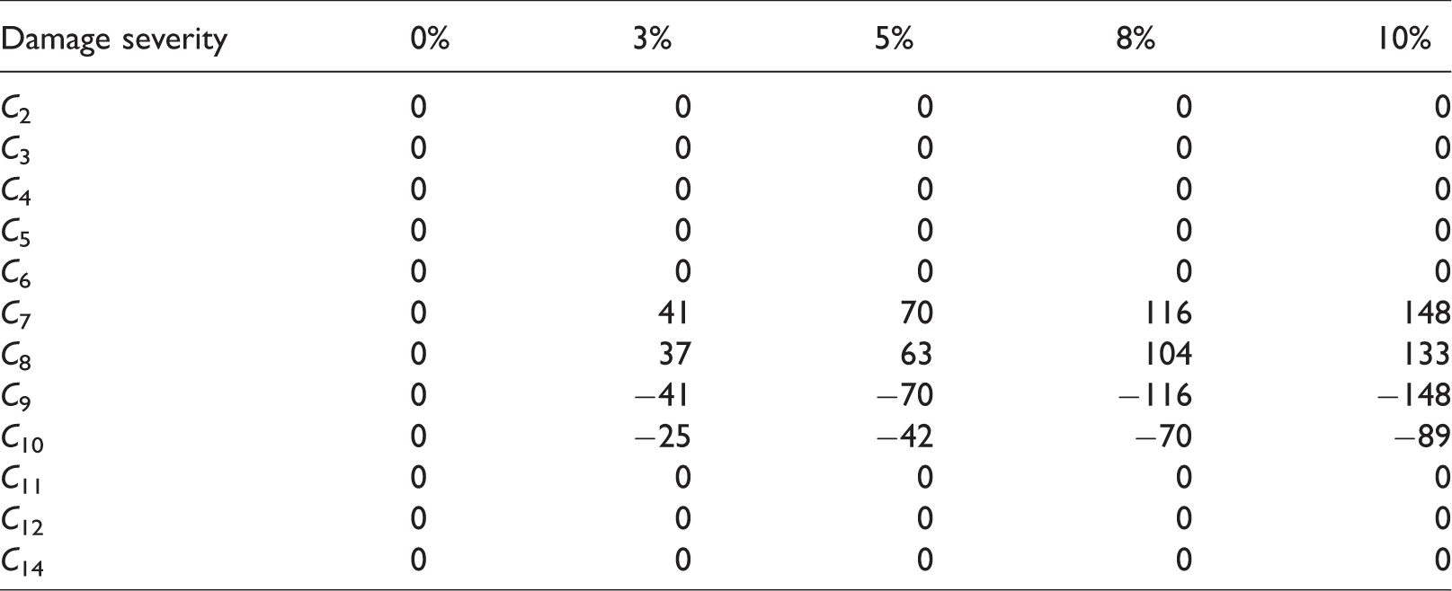
The damage assessment results given by CSP, ARR and IARR are listed in Tables 1 and 2, respectively. It can be seen from Table 1 that in the undamaged state, all the constraints are zero for this numerical beam without the influence of uncertainties. But when the damage occurred with a severity of 3%, only the constraints related to the damaged element 4 (C7, C8, C9 and C10) changed while the other constraints remained zero. Meanwhile, the relevant constraints’ absolute magnitudes monotonously increased with the increase of damage severity.
Damage assessment of the numerical beam by constraint satisfaction problem.
Damage assessment of the numerical beam by ARR and IARR.
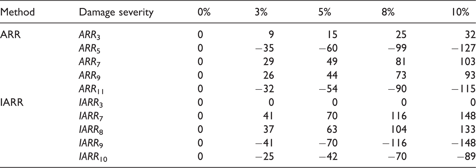
Note: For clear comparison, the increments of ARR and IARR with respect to the first load step are given. ARR: analytical redundancy reduction; IARR: improved analytical redundancy reduction.
As to the ARR method, only ARR7 and ARR9 were linked to element 4 whose damage only affected these two constraints while the others remain consistent. However, it is observed from Table 2 that all the ARRs turned to be inconsistent when element 4 was damaged. This observation proves the aforementioned description that ARR is incapable of damage location. On the other hand, the magnitudes of IARR7, IARR8, IARR9 and IARR10 changed when element 4 was damaged with a severity of 3%. At the same time, the irrelevant constraint IARR3 always remained zero, which confirmed the appearance of damage on element 4. The absolute magnitudes of these constraints also increased with the severity increase of the damage. Therefore, it is concluded that the proposed IARR method can well locate the damage and somehow estimate the severity.
It should be mentioned that for a CSP solution, the successful implementation highly relies on the measurement of sectional rotations, which is very difficult to achieve in real-world structures. Moreover, in this numerical example uncertainty factors such as model errors and experimental noises were not involved in the analysis. Therefore, for the subsequent experimental example, equation (6a) was used for damage assessment.
Experimental validation
Description of the experimental beam
In the interest of verifying the proposed method against practical structures, an identical steel box beam was statically tested in the laboratory, as is shown in Figure 3. The measured material properties were elastic modulus of 202 GPa, the yield strength of 343 MPa and the ultimate strength of 450 MPa. The beam had a length of 2.0 m and a calculated span of 1.8 m due to the simply supported boundary condition. As that was adopted in the numerical example, a concentrated load was applied at the same position with an increment of 1 kN (Figure 1). Five micrometers were used to record the beam deflections, and 2 micrometers were used to measure the settlement of the bearings.
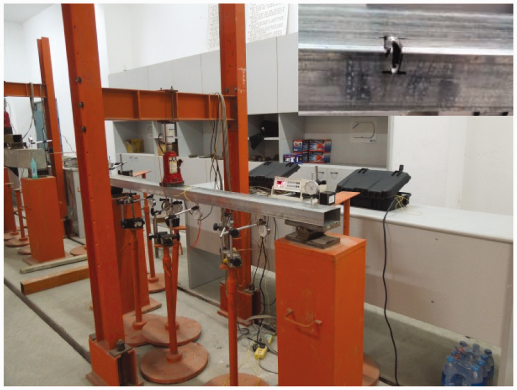
Static loading and damage simulation of the experimental steel beam.
In the numerical study, the damage was simulated by the stiffness reduction of element 4. But in the test, the damage was given by a cut at the section of the beam when the load arrived at 4 kN. The width of damage remained at 8 mm, and the height varied from 20 to 30 mm. When the beam was being cut, the load was held, and the deflection of each control section was recorded. It is noted that the experimental beam was also divided into six segments (like elements for the numerical beam) for analysis.
Damage assessment results
In this experimental case, the CSP method was not considered because it was very difficult to measure the sectional rotations of the box beam, saying nothing of the measurement accuracy. Moreover, one objective of this study is to use only translational measurements such as deflections that are relatively easy to obtain in practice.
It can be seen from Table 3 that the ARR method still cannot locate the cut damage since ARR9 and ARR11 related to element 5 seems damaged worse than the actual damaged element 4. For the IARR method, it is found that the magnitudes of IARR7, IARR8, IARR9 and IARR10 related to the damaged element are much larger than IARR3. And the magnitudes of IARR3 change little. This observation may confirm the damage of element 4. It is also found that the deviation levels increase with the increase of the cut length (damage severity).
Damage assessment of the experimental beam by ARR and IARR.
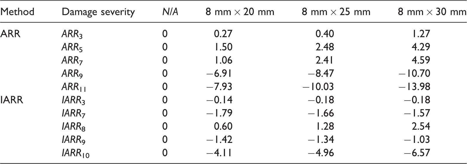
Note: The data represent the constraint deviation levels expressed by equation (12). ARR: analytical redundancy reduction; IARR: improved analytical redundancy reduction.
Conclusions
For the purpose of practical application, an improved analytical redundancy relation method has been proposed for structural damage assessment. Through both numerical and experimental case studies, the IARR method was compared with the classic CSP and ARR methods and some conclusions are obtained as follows:
The CSP method can locate the damage if both translational and rotational displacements are ready. However, accurate sectional rotations are generally very difficult to measure in practice, which limits the application of the CSP method. The traditional ARR requires only translational displacements but it cannot realize damage location. By adjusting some equation positions in the decomposition of a static equilibrium matrix, new constraints are established for the IARR method. The damage can be well located by the changes in the magnitudes of IARRs related to the pre-assumed damaged element. In this aspect, the IARR method shows it superiority over the CSP and ARR methods. For further validation, the proposed IARR method could be applied to more complex structures such as a continuous bridge. The deflections at the key sections of the bridge spans can be used as the measurements for establishing constraints.
Footnotes
Acknowledgements
The authors are grateful to the reviewers for their constructive comments.
Declaration of conflicting interests
The author(s) declared no potential conflicts of interest with respect to the research, authorship, and/or publication of this article.
Funding
The author(s) disclosed receipt of the following financial support for the research, authorship, and/or publication of this article: The research is supported by the National Natural Science Foundation of China (grant no. 51578158) and also by the Qishan Scholar Program of Fuzhou University (grant no. GXRC-1688).