
Abstract
This paper considers the problem of position control and active vibration damping of a planar, array (or grid) of masses and springs, by a single actuator, attached to one corner of the array, which is required to translate and rotate the entire system from rest to rest, through target linear and angular displacements, simultaneously. An obvious challenge is that the system has many degrees of freedom, with many undamped vibration modes, and is clearly highly under-actuated. The control technique is a development of “wave-based control,” whereby rapid and effective control of the entire system is achieved, robustly, using measurements made only at the actuator, of the actuator’s own motion and of the forces between the actuator and the attached flexible system. No detailed system model or system identification is needed. The actuator need not be ideal. The array does not have to be uniform, in its geometry or in the mass and spring values. The control strategy is simple to implement. The 2D array is of interest in itself as a benchmark control challenge, but it can also be considered a model of various lumped structures, or a discretisation of distributed systems.
Keywords
Introduction
Among many methods applied to single-actuator, position control of lumped or distributed flexible mechanisms (see, for example, literature1–7), wave-based control (WBC) provides a low-cost, precise, robust, rapid and effective strategy.8–17 It has been well studied for rectilinear systems (1D cascades of masses and springs) for rest-to-rest motion, with the same actuator combining position control and active vibration damping, simultaneously. This work is a novel development within the context of WBC to present its adaptability and ability to cope with a very flexible, array-like structure with many degrees of freedom. It is mentionable that using classical approaches, for example, a finely tuned PID controller while utilising a number of feedbacks and sensors located across the array may lead to the roughly similar performance and results as obtained and shown here. However, it should be emphasized that for a similar response resulted by other controllers, WBC has many advantages over the commonly used approaches which makes it distinct. As will be seen, these include simplicity of the technique, ease of implementation, ‘no requirement for a system model’, ‘no need for any extra measurement or sensor in the system except at the actuator's output’ and therefore being a very low-cost and economically efficient controller while presenting itself stable and very robust to modelling, actuator and to implementation errors. These later benefits have been identified in the literature on WBC area.8–17
Also, some control methods with satisfactorily standard performance are based on modal analysis. But it has been reported that these methods usually suffer from mode truncation (ignoring of higher modes) and mode spillover (unintended excitation of higher modes) effects. 4 The modes then need to be identified in real time and somehow controlled, often by a single actuator (or more likely with fewer actuators than degrees of freedom). In fact, modal analysis represents the motion of the system in terms of the superposition of synchronous motions (mode shapes and mode frequencies). There is a sense in which it implicitly assumes synchronous (periodic) motion. These controllers are based on identifying and measuring the modes and then moving the actuator to try to control them explicitly. They then have concerns about modal truncation and mode spillover. By contrast, WBC strategy completely avoids the modal or frequency domains and works entirely in the time domain. Unlike other methods, WBC does not wait for modes to become established and identified before controlling them. In fact it does not interpret the vibrations as modes but as travelling waves, which are then controlled on arrival back at the actuator. To wait for modes to become established is to wait too long. The transient is all-important, especially for rest-to-rest manoeuvres. If an approach does not control the transient directly, the controller will be poor and slow.
WBC sees the actuator as launching displacement “waves” into the flexible system while absorbing returning waves on arrival back to the actuator. In what follows, the term “waves” refers to a change in displacement, or simply a motion disturbance, which is considered to propagate through the system, dispersing spatially and temporally as it goes. The controller gives an input motion request to the actuator, which is the sum of two components. The first is considered as the actuator’s launch wave, set by the controller, with a net displacement of half the target actuator displacement. To this, it adds the measured wave returning to the actuator from the flexible system. It measures this returning wave at the actuator output, that is, where the actuator interfaces with (acts on, and is acted upon by) the flexible system. The sum of the launch wave and the measured returning wave becomes the request displacement input to the actuator. For an ideal actuator, this becomes the actuator motion.
In the absence of external disturbing forces, the absorption of the returning wave by the actuator causes the system to move the second half of the target displacement while actively absorbing the system vibration. Thus, position control and active vibration damping are seamlessly combined, being completed together. This synchronised completion is necessary, since if one is achieved without the other, further actuator motion will be needed to achieve the second requirement, which will necessarily disturb the achievement of the first.
The present work investigates the extension of these ideas to single-actuator control of 2D arrays (grids) of point masses and interconnecting springs, as in the upper right of Figure 1. In addition to re-positioning in the 2D plane to a target x and y displacement, there is now the added challenge of rotational motion, say to a target angular displacement, θ, all to be achieved by the controlled motion of a single L-shaped actuator, ABC, here chosen to be at one corner. Each of these three motions (x, y and z) takes a reference or target displacement as shown in Figure 1 and first multiplies it by ½. This half reference input becomes the “launch” wave, that is the launch part of the actuator’s motion for that component of the manoeuvre (x-, y- or θ-motions). To these, half-reference inputs are added what is here called the returning wave motions, [x, y, θ]b. These can be determined in different ways.8,11,17 The lunching and returning waves will be introduced further in ‘Control implementation’ Section. It is mentionable that the signals used here as the reference are simple ramp inputs to the controller’s actuator which could be produced by a signal generator and given arbitrarily chosen values as the target displacement of the system’s tip. Since the references and target displacements for different manoeuvres in this work are chosen almost differently, they will be detailed in the following within the corresponding descriptions of each manoeuvre and its response.
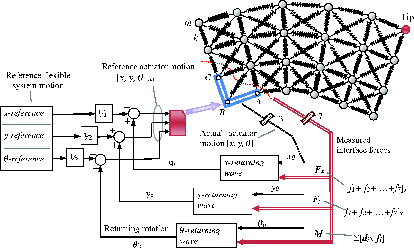
WBC of a 2D structure modelled as a mass-spring array. The measured variables for control are the actual actuator x-y position and angle θ, and the forces at the actuator-system interface (in seven springs).
The lumped flexible array can be considered a benchmark challenge for 2D flexible system control strategies in general as its sample applications can be well found in Gohari et al. 18 and Tiwari et al. 19 But it can also be considered a generic model of various systems of engineering interest. Thus, by choosing suitable mass and spring values, and grid shapes, it is possible to model, for example, distributed plates and beams of specific elastic constants, 19 , 20 or predominantly lumped devices ranging from micro-electromechanical devices, micro-surgical tools through manipulators and robot arms, up to heavy-duty cranes and large space structures. 21
In the 1D rectilinear case, with a simple string of masses and springs, 8 the displacement waves have a single, two-way path, from actuator to system tip and back again, which somewhat limits the dispersion (although some dispersion is always present). In the 2D system, by contrast, there are multiple, complex wave paths from the actuator to the system boundaries and back again, and hence the dispersion and wave mixing are even more noticeable. The number of degrees of freedom is high. A further complication is coupling between transverse (shearing/rotational) motion and longitudinal motions in different directions throughout the grid. It was not clear beforehand, therefore, if the WBC ideas would work, and, if so, how well.
Typically, the goal is to move the system tip (the corner furthest from the actuator), from rest to rest, to a target position and angle. This in turn implies control of the entire flexible array, and also of any other point of interest in the array.
Flexible system model
The system of masses and springs was modelled by a straightforward computer simulation. The magnitude and direction of the forces on each mass were determined from its own position, the relative positions of neighbouring masses (or of the actuator itself for some of the masses), combined with the known spring stiffness values. The resulting accelerations were then integrated to get the new velocities and again to get the new positions, from which the forces could be determined for the next integration step. Both external damping (viscous damping to ground) and internal damping (viscous damping proportional to relative velocities) were included in the model. For the results presented below, however, all damping was set to zero, so that the only source of damping was the active damping due to the control system in the actuator. Also, gravity was not considered in the work presented here, so that the grid can be considered to be moving in a horizontal plane, or in a micro-gravity environment.
All motion was initiated by moving the actuator. Initially the actuator was assumed to be ideal, so that the actual actuator motion was made equal to the reference actuator motion. Later realistic actuator dynamics were added, which included the effects of dynamic loads due to the attached flexible system. In the second case, the actuator was assumed to have its own sub-controller, responsible only for ensuring that the actuator’s actual motion followed the reference actuator motion as closely as possible. The WBC was at a higher level, at which the details of this sub-controller were of no concern.
Control implementation
The basic ideas about WBC, especially for 1D rectilinear systems, have already appeared in the literature8,10–12 and will not be reproduced in detail here. Here, in the 2D case, as in the 1D case, the entire control strategy focuses on the interface between the moving actuator and the flexible system. This interface is seen as a two-way gateway for energy and momentum transfer between the flexible system and the directly controlled actuator (see Figure 2).
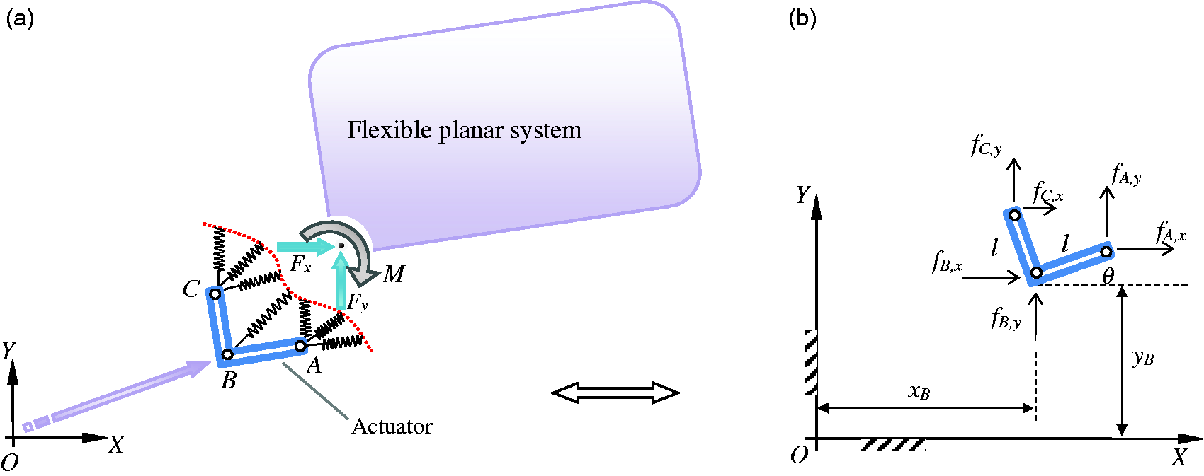
Details of the loading situation in interface; (a) Equivalent applied loads on the grid from the actuator through a typical manoeuvre; (b) Applied forces on the connecting joints of the displaced actuator.
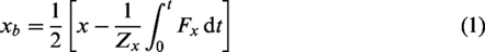
Two sets of measurements are required. The first concern the translational and rotational position of the actuator itself, say [x, y, θ], which will probably be available from the actuator sub-control system. The second are the interface forces which, in this case, correspond to the forces in seven springs, whose x and y components are
As already mentioned, the WBC happens at a higher level. A relatively simple arrangement gives very good results, as will be seen. It is actually organised as three 1D WBC systems acting in parallel, one each for x, y and θ motions, as explained earlier in the description of Figure 1. Each 1D system will then include the two distinct ‘launching wave’ and ‘returning wave’. The simplest, and the approach adopted in this paper, defines the three returning waves as
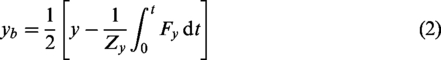
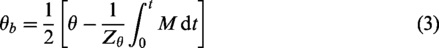
Here the Z terms are impedances with constant values in a given control system. The actual value is not critical: only the order of magnitude is significant. Varying the value provides some fine tuning of the final control system. Zx and Zy can be set to √(km), at least initially, where k is a representative stiffness of the springs in contact with the actuator, and m is a representative mass. In this work, Zθ was set to √(10 km).
Then, for example, the x-motion component which the actuator sub-controller is asked to follow becomes
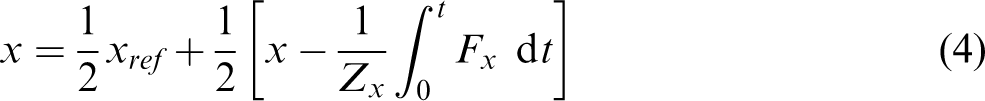
The addition of the returning wave components to the launch wave components of the actuator motion has two important effects. The first is that it causes the actuator to act like an active viscous damper for motion in the flexible system arriving back to the actuator. The equivalent viscous damping coefficients have values equal to the impedances. The second important effect is that, for a rest-to-rest manoeuvre, when, say, xref reaches its new value and becomes constant, the addition of the returning component quickly supplies the second half of the reference motion, causing the system to settle at the target position. In equations (1) to (3), the force or moment integrals become zero on settling, because the initial and final momenta (linear or angular) are zero. Thus, at the new steady state, xss = ½ (xref + xss) and so xss=xref, as required. The same applies for the other two motion variables. In this way, planar position control and active vibration damping are seamlessly combined into a single motion of the actuator for all three aspects of the motion.
Regarding the rotational motion, if the point B in Figure 1 is taken as the moment axis, the control system using the rotational returning wave, equation (3), behaves exactly as required provided there is no simultaneous translation of the actuator. If, however, there is simultaneous translation, there will often be a small steady-state error in the final angle. Obviously this could be corrected by a further rotational manoeuvre, but a more elegant solution is available. The source of the error is that, even in a rest-to-rest manoeuvre, angular momentum about B is not necessarily conserved if B moves, and so the integral in equation (3) does not return to zero exactly. The simplest way to avoid this (frequently small) error is to take moments, not about a moving axis such as B, but about a fixed axis, such as the original position of B (which is O in Figure 2). Alternatively, one could take moments about the mass centre of the grid, requiring continual recalculation of its position over time. Either solution ensures zero steady-state error in the final position. In either case, the system can then deal with simultaneous translational and rotational motion to a new target position with zero final error in all three target values.
As in the 1D case, the shape of the reference inputs over time is arbitrary. They can be steps, ramps or s-shaped parabolic signals, for example, provided only that the final steady-state values correspond to the desired final position and orientation of the actuator. There is scope here to optimise the input waveforms, for example to achieve minimum time manoeuvres. 9 But simple inputs, such as ramps up to the target values, work so well in most cases that trying to do better is hardly worth the effort.
If, instead of the actuator, it is desired to get another part of the system, such as the tip, to a target position and orientation, it is a matter of simple geometry to adjust the target final actuator positions so that the part of the system of interest ends up in the position required, with the correct target angle. (Obviously if the only requirement is that the tip be at target x and y values, there is an infinite number of angular positions θ which would achieve the same position.)
Cross coupling of motions
In complex flexible systems such as this, there is generally strong cross-coupling between translational and rotational motions. One of the motivations for this work, therefore, was to investigate how this cross coupling would affect the WBC in Figure 1, with its three parallel controllers, one for each aspect of the motion.
Consider, for example, the flexible array starting with θ = 0, with the free sides parallel to the x and y axes. Suppose it is desired to move it in the y-direction only (with no displacement in the x and θ directions). The actuator’s y-motion has a shearing action on the flexible array, but it also has rotational (torque-like) effects, attempting, as it were, to keep the grid from rotating at the start and end of the manoeuvre. The actuator will experience a time-varying torque and it, in turn, is applying a torque in reaction.
To achieve this y-motion under WBC, there are at least three possibilities. In Figure 1, one could use exclusively the y component of the control system, with the x and θ controllers simply turned off. In other words, the entire launching and absorbing motions of the actuator are exclusively in the y-direction. There might be a requirement to use such a control strategy if the actuator had only one degree of freedom, in the direction of motion, and so x and θ motion were not available. As will be seen below, this simple, one-dimensional approach works as desired.
If instead one assumes that the actuator has all three degrees of freedom, a second control option is to launch them as before, but, in addition to absorbing again the measured returning y-motion, to measure and absorb motions simultaneously. When this is implemented, it gives better vibration control, but in general, the final positions will be incorrect. Furthermore, the final errors in the three variables are difficult to predict. The x and θ absorbing takes from the y absorbing. It is as if the actuator finds the easiest and fastest way to absorb the vibration energy and momentum, using whatever variables it can control, but in doing so it allows the three component motions to become mixed in an unpredictable way. For this reason, this option is unlikely to be used in practice, unless rapid, active vibration damping takes absolute priority over position control.
A third option, which easily solves the mixing aspect, is to implement full control of all three variables, as in Figure 1, even though the reference inputs to both the θ and x motions would be zero in this case. The θ and x controllers would still contribute to the absorbing, but now the reference input values (which happen to be zero) will ensure that the final values are correct. This third arrangement, as envisaged in Figure 1, will generally be the default when x, y and θ actuation are separately available. It gives very good results, as will be seen, combining good vibration control and zero settling error.
Similar cross coupling effects between component motions will arise in any given manoeuvre, involving changes in one, two or three of the motion variables. In all cases, the configuration of Figure 1 gives the desired performance, simply and robustly. To illustrate the above, some sample results will now be presented.
Results
To validate and illustrate the approach, a model consisting of a 4 × 4 lattice geometry was set up, with 1-kg masses and interconnecting linear springs of k = 10 N/m stiffness, with no damping, whether internal or external. The flexible part of the model therefore has 13 degrees of freedom (the actuator occupying 3 lattice points) and is very flexible, especially with such low-stiffness springs. In the control system, the measurements of force and displacement were obtained from the model springs and actuator position. The responses to various reference inputs were then investigated, with different levels of control in the three parallel aspects of the WBC system shown in Figure 1.
In the first case, control was applied in the x-direction only, with the only feedback coming from the x-returning wave, as if controlling the 2D system with a 1D control system, with the control of the y and θ variables suppressed. Figure 3 shows the tip response for a target displacement of 1 m, with a ramp input waveform of 0.5 m/s. Also shown are the actuator motion producing and controlling the motion, the x-returning wave, xb on which this is based, and the y-motion of the tip. It can be seen that the system moves rapidly from rest to rest at the new target position with good vibration damping.
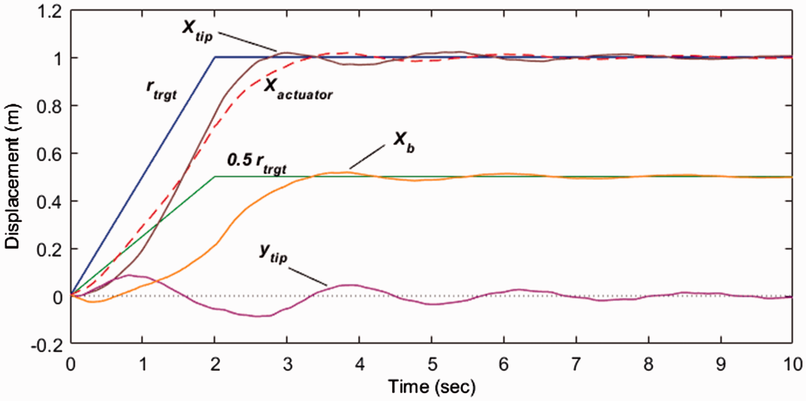
System response for 1 m displacement using only x-direction returning waves in the controller.
As discussed above, the x-motion also excites y and θ motions. Figure 4 shows the tip response to the same reference input but now with the y-return and θ-return motions also acting on the actuator. Now the performance is even better, with negligible overshoot and very rapid settling at the target. Even though the final displacement of the actuator is identical, the fact that it also uses y and θ motions to control the vibration ensures a better response, especially in the active vibration damping but also in the absence of overshoot.
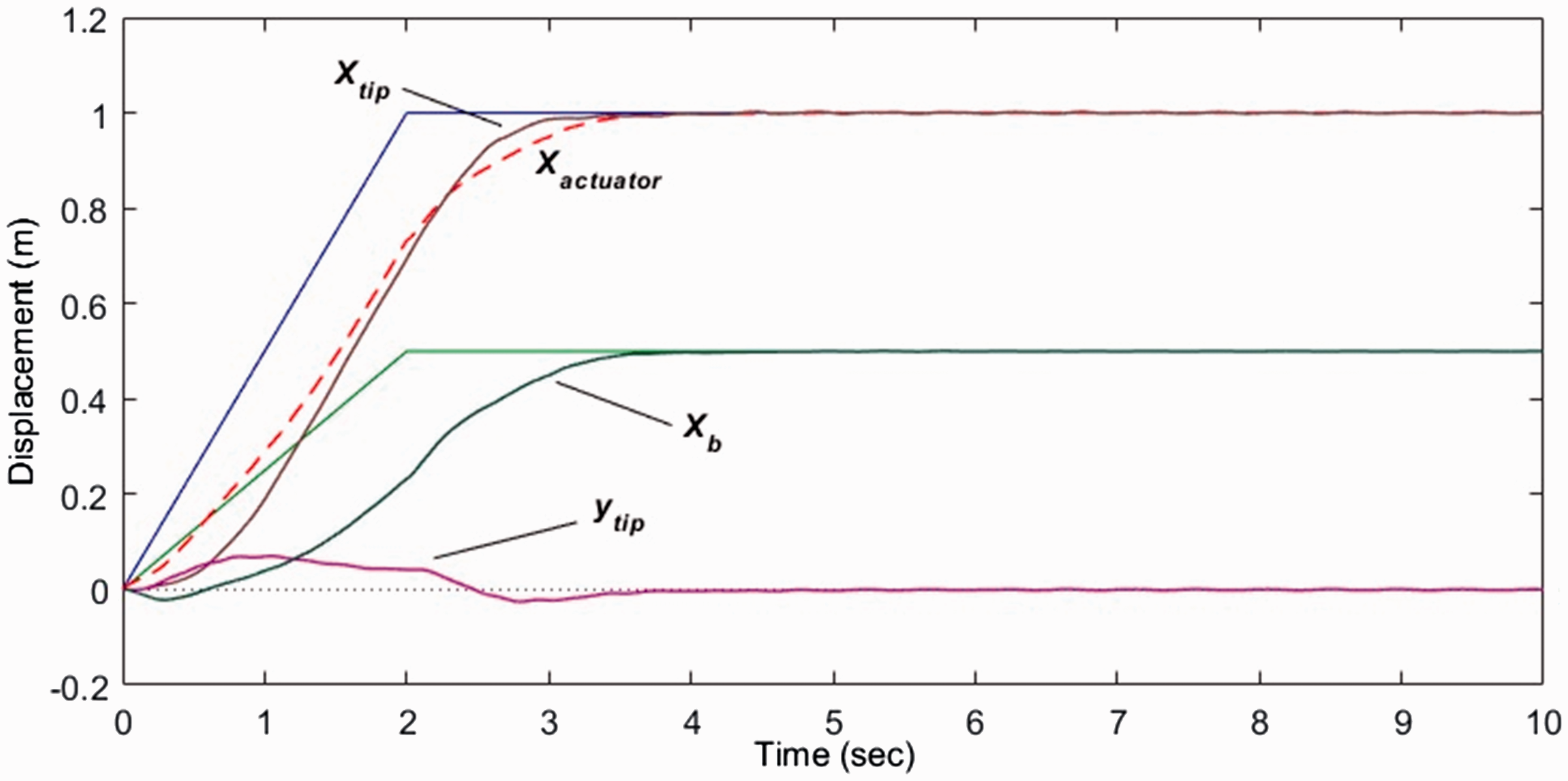
The same manoeuvre as in Figure 3 but using x, y and θ return waves in the controller.
For the results shown in Figure 5, the target tip displacements (reference inputs) in the x and y directions were 0.4 m and 1 m, respectively. The actuator was allowed motion only in the x and y directions, with all rotational (θ) motion suppressed. In other words, all absorbing of returning motion had to be achieved by x and y motions exclusively. The x and y reference inputs were simultaneous ramps of different slopes. As can be seen, the tip response is very good. Also shown are the returning waves for each of the component motions. Although not shown here, the results are even better when the actuator is also allowed to rotate and WBC (with zero reference input) is simultaneously applied to the θ component of the motion.
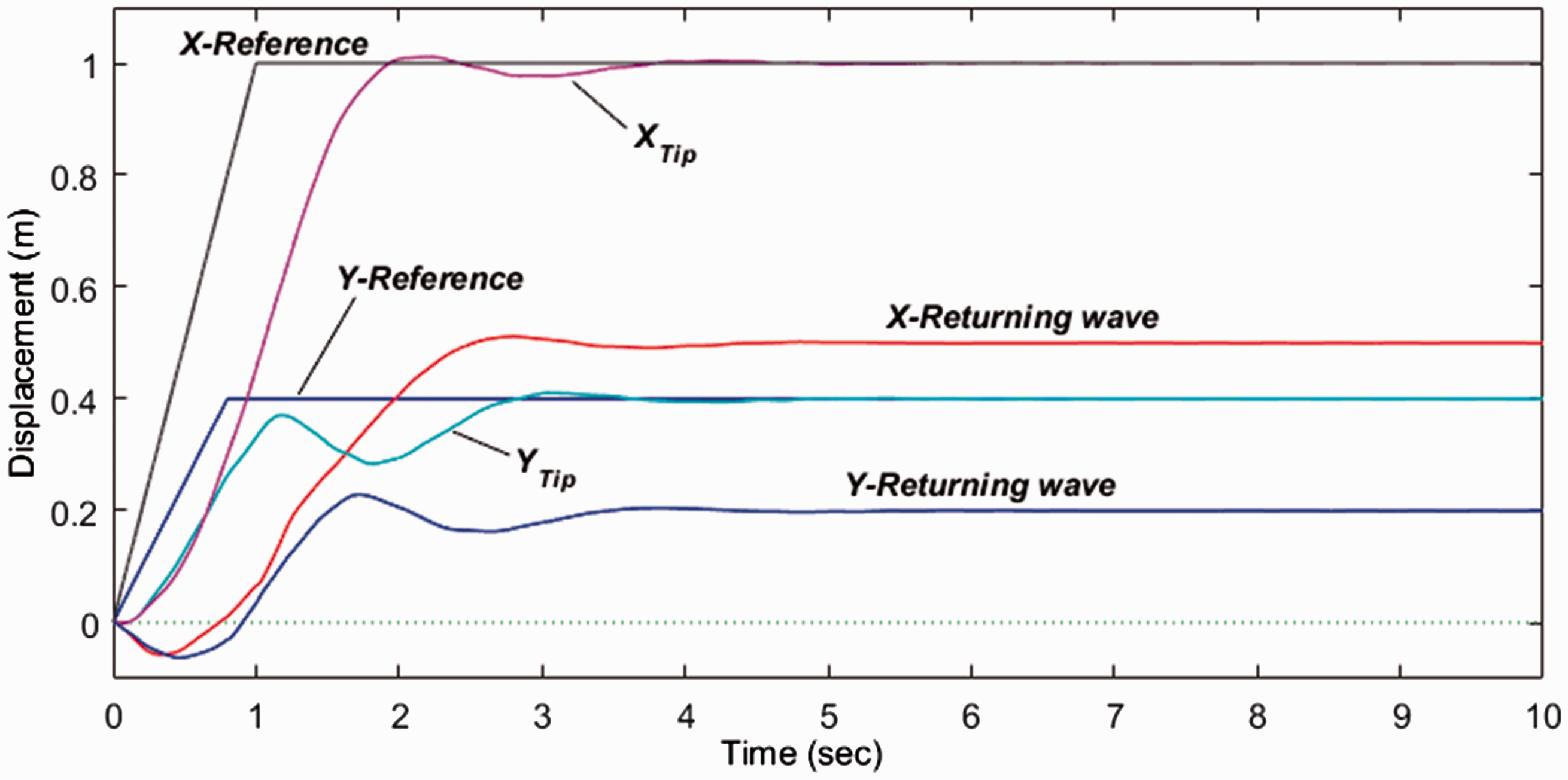
WBC of the grid which moves in both x and y directions in a plane using same returning waves in the controller.
Figure 6 shows a fairly rapid system rotation through 1 radian with all three returning motions used in the control system. Considering that this system is very flexible, with many degrees of freedom, zero damping, and a single actuator acting at only one corner, the rest-to-rest transit and settling are remarkable.
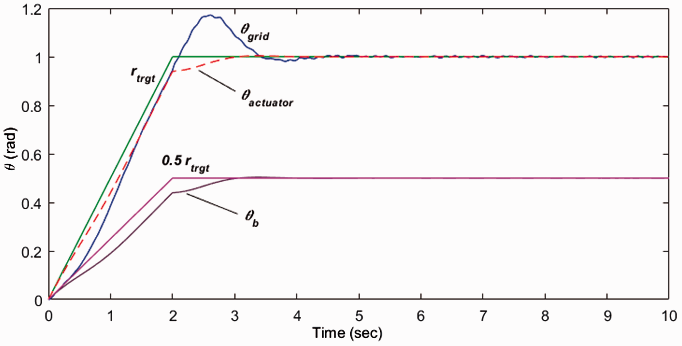
A system rotating through 1 radian using x, y and θ returning waves.
Finally, Figure 7 shows a sample response when all three component motions are applied and controlled simultaneously. In this case, the (quite arbitrary) target values were x= 1 m, y = 0.6 m and θ = 0.3 rad, created by three ramped inputs of different rates (also arbitrary). Despite the simultaneous combination of different launching waves, the WBC control system achieves a very good response with a rapid transit to the new position, negligible overshoot in any of the variables, rapid settling, and zero steady-state error.
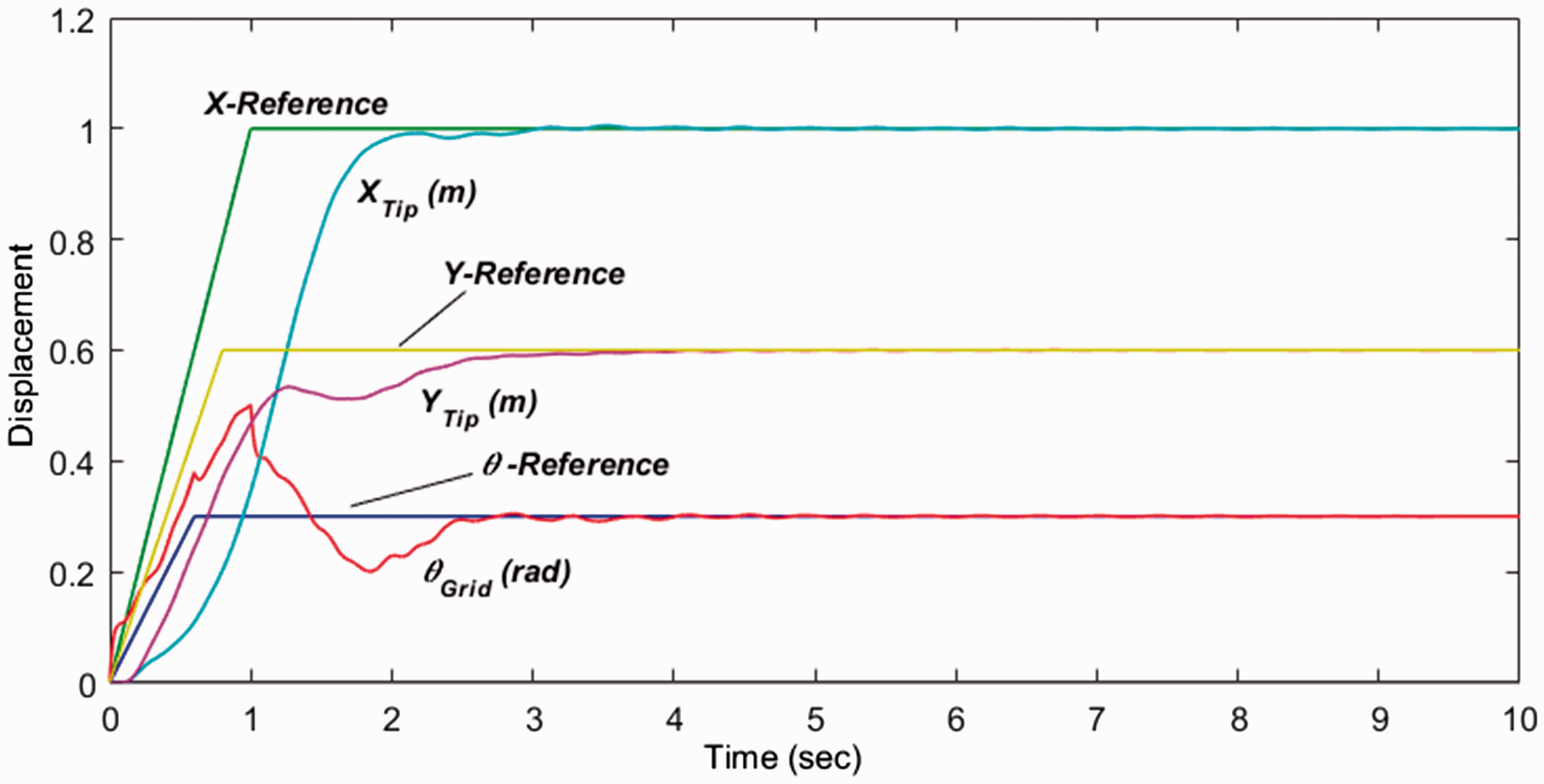
WBC of the grid for a complex input as three-component reference of x, y and θ.
It is mentionable that although the goals of positioning and vibration suppression were achieved here, however, a small residual vibration of relatively high frequency left in the system after some of the manoeuvres reach the target which could take a relatively long time to be absorbed completely. Given the dispersive nature of the flexible system, and the complete absence of any kind of damping in the model, the existence of such small lingering vibrations is hardly surprising. Rather, the surprise is that they are very small with the amplitude of order 10−4 m for, e.g., a 1-m displacement of the system in the directions x and y. The addition of even small internal damping will quickly eliminate these high frequency oscillations. The whole topic of residual vibrations in rest-to-rest manoeuvres under WBC is a topic of another ongoing study as a prospective publication associated with the current paper. So this subject is not considered in further detail here.
In terms of stability, it should be noted that the presented control strategy is closed-loop and collocated with the actuator as the same as the previous work in the WBC area, which is one important reason for its stability. In fact, WBC combines the best features of open loop controllers (anticipating errors before they arise) and feedback control (which corrects for departures from desired behaviour, albeit using measurements taken at the actuator). But in so far as it has “feedback” it is not the conventional, output-error-correcting, negative feedback: rather it is a positive feedback which, in part, anticipates the error (tip overshoot and oscillation) and inhibits its occurring, in an inherently stable way. The signal for this “feedback” is obtained by processing two measurements made at the actuator in a special way. In fact, the arrangement resembling positive “feedback” is actually providing active vibration damping as well as position control as it moves the system the second half of the launch displacement leading to bringing the system to rest at target. It causes the actuator to behave, to a returning wave motion, as a passive damper, tuned to minimise reflection and maximise absorption of the returning wave, analogous to a matched impedance at the end of an electrical transmission line. This is also what makes the controller so stable.
In this regard, a pole-zero analysis carried out by McKeown, 17 also shows that this standard form of WBC pulls the poles, which previously, in the uncontrolled, undamped flexible system, lay on the imaginary axis in the s-plane, off the imaginary axis and into the left hand half to the s-plane. Indeed, a standard implementation of WBC completely eliminates the poles present in the uncontrolled flexible system (except for a single pole at the origin) and thereby brings about the stability of the system.
In addition, although not displayed here, other aspects were also investigated in this study. The shape of the mass-spring array was changed, for example to make it long and thin, that is, more beam-like. Similarly satisfactory results were then obtained without having to change the control strategy. Also, the values of mass and spring elements were varied, and again the same controller still gave very good results. This robustness to system changes is mainly due to the fact that the control law is based on the returning wave motion, which in turn is determined by the system dynamics, whatever they happen to be. The controller does not need to model them, or to know them. It simply waits, observes, and then moves to absorb them. This could be considered real-time system identification.
Conclusion
This work proved that a relatively simple generalisation of the WBC motion control strategy, despite the added challenge of the dynamics of the 2D array system and its many degrees of freedom performs very effectively while it retains many attractive features of these control techniques. These considerable features include the speed of response, zero steady-state error, robustness to actuator limits, small overshoot, robustness to system changes, no requirement for a detailed system model, and rapid settling, all achieved with a simple, low-order controller. Finally, preliminary results soon to be reported indicate that the same approach is easily extendable to the control of spatial flexible structures with deflections in 3D, where the controlled system has much more complex dynamics and the actuator has six degrees of freedom.
Footnotes
Declaration of conflicting interests
The author(s) declared no potential conflicts of interest with respect to the research, authorship, and/or publication of this article.
Funding
The author(s) received no financial support for the research, authorship, and/or publication of this article.