
Abstract
The survival of the crack in structures always keeps the structure away from performing well in applications due to significant changes in its dynamic response. It has been observed that in service the size of the crack in structures increases with time and finally it leads to its catastrophic failure. Hence it is crucial to do the vibration study of cracked beams in regard of free vibration-based crack detection and its crack classification. Until now the vibration-based nondestructive testing methods are applied to many spring steel cracked cantilever beams for its possible crack detection. However, the effect of various kinds of practical cracks, i.e. V-shaped, U-shaped and rectangular-shaped open cracks, on the applicability of these methods has been overlooked. In order to investigate this issue, artificially cracks are made on the cantilever beam. By free vibration analysis, the effect of crack geometry, crack depth, and crack location on the beam stiffness is investigated. In this study, the stiffness of each cracked case is computed by the deflection methods and vibration methods to ensure the strong validation. The stiffness results obtained from V-shaped, U-shaped and rectangular-shaped crack models for the same configuration are compared with each other and it is found that the results of the stiffness are comparatively more sensitive to U-shaped crack models. Through vibration study, it is found that spring steel structures are slightly sensitive to the change in crack geometries as long as the vibration characteristics are concerned. Hence, it is obvious that free vibration-based crack detection method can satisfactorily predict the location and depth of the crack in any spring steel structures irrespective of the crack geometries. Apart from this, it is also found that for the same configurations, EN 8 and EN 47 cracked cantilever beams give the identical structural integrity or structural stability property for all the cracked cases. Lastly, it is also found that as the crack depth increases by keeping the crack location constant, the stiffness of the beam decreases.
Introduction
Spring steel materials are widely used in various structural applications in the automotive, civil and mechanical industries. One typical application of spring steels in structures is beam. In machinery and civil structures, members in the form of cantilever-type of beams are widely used. Common examples are turbine blades, cantilever type of bridges, and tall building structures. A defect-like crack in a beam develops with time and gives terrible failure of the beam, hence vibration-based crack detection and its classifications are important issues in the regard of its condition monitoring. Saddetin 1 studied the cracked cantilever beam for the free and forced vibration analysis. This study primarily deals with the identification of the crack parameters in a beam. Single- and two-sided cracks were evaluated for the vibration parameters, i.e. natural frequency and resonant amplitude. The results of this study suggest that free vibration analysis provides the suitable information either for detection of single- or double-edged cracks and on the other hand forced vibration information is appropriate to detect the single-edged crack condition. Zhong and Oyadiji 2 considered the polynomial function for the obtaining the transverse deflection of the cracked beam. The polynomial function represents the effect of a crack. Vigneshwaran and Behera 3 studied the dynamic characteristics of a beam with multiple breathing cracks. For developing theoretical expressions for evaluation of natural frequencies and mode shapes, a systematic approach has been adopted in this study. For performing the dynamic analysis, a simple elastic, simply supported beam with two breathing cracks is considered. The concept of influence coefficient is used to determine the cracked beam stiffness. Sadettin et al. 4 introduced the new crack model, not like the widely known V-shaped crack. They investigated the effect of crack depth on the natural frequency of a composite beam. Krawczuk et al. 5 studied the cracked composite beam and found that vibration parameters like natural frequency changes due to the presence of crack in a composite beam. Dirr and Schmalhorst 6 studied the propagating crack that causes the slender uniform round shaft to shake about its major axis. Experiments using a stationary shaft are also performed. To measure the crack depth and the actual shape of the cracked cross section, beach marks have been used. Khanna and Singhal 7 presented a mathematical model to analyze the vibration of a tapered isotropic plate under thermal condition. Tapering in the thickness of rectangular plate is considered bi-parabolic. They assumed the temperature variation bi-linearly, i.e. variation in the temperature along the X and Y directions. The first two modes of the rectangular plate are calculated for the various boundary conditions. Liu et al. 8 developed an optimal delayed feedback control methodology to mitigate the primary and super harmonic resonances of a flexible, simply supported beam with piezoelectric sensor and actuator. Stable vibratory regions of the feedback gains are obtained by using the stability conditions of eigenvalue equation. Attenuation ratio is used to evaluate the performance of vibration control by taking the proportion of the peak amplitude of primary or super harmonic resonances for the suspension system with and without controllers. The piezoelectric optimal controllers are designed to control the dynamic behavior of the nonlinear dynamic system. It is found that the optimal feedback gains obtained by the optimal method result in good control performance. Xia et al. 9 built up an optimized support vector regression model to predict the damping ratio of the cantilever beam with particle damper. Then, the optimal parameters are adopted to construct the support vector regression models. Cross validation combined with support vector regression is used in this research and is compared with the genetic algorithm-support vector regression method. The experimental results demonstrate that the proposed genetic algorithm-support vector regression model provides better prediction capability. Beni et al. 10 provided the new model by using the couple stress theory for the anisotropic carbon nanotubes. In this research study, they used the Hamilton’s principle and then motion equation and boundary conditions of carbon nanotubes are extracted by considering the couple stress theory. After that, equations are solved by using the analytical solution method. Lastly, the carbon nanotube is investigated for the anisotropic effect.
From the literature survey, it has been found that V-shaped, rectangular-shaped and U-shaped cracks frequently occur in structures. The presence of such cracks in structures is universal and it leads to change the structure dynamics to a considerable degree. In earlier studies, a cracked cantilever beam was investigated for the free vibration by considering mainly the natural frequency. Less work seems to be reported for the cracked cantilever beams study by considering the stiffness, hence it needs attention. In this study, U-shaped and rectangular-shaped crack models are introduced together with a regular V-shaped crack model in order to investigate the effect of defect geometry change on the stiffness of a cantilever beam by free vibration analysis. This investigation is required to evaluate the applicability of free vibration-based methods for the crack detection.
Theoretical method of analysis of natural frequency of an uncracked cantilever beam and its application to cracked beams
The schematic diagram of an uncracked cantilever beam subjected to zero frequency point load is shown in Figure 1. From Figures 5 and 7, it is observed that the deflection curve of a cantilever beam at zero frequency is approximately similar to the curve obtained when the beam vibrate with the first natural frequency. Hence, the integration-based approach is applied to an uncracked cantilever beam to get its kinetic energy. Then the formula of the potential energy of the beam is also derived. Lastly, energy principle is used to derive the natural frequency formula shown in equation (1) of an uncracked cantilever beam
11

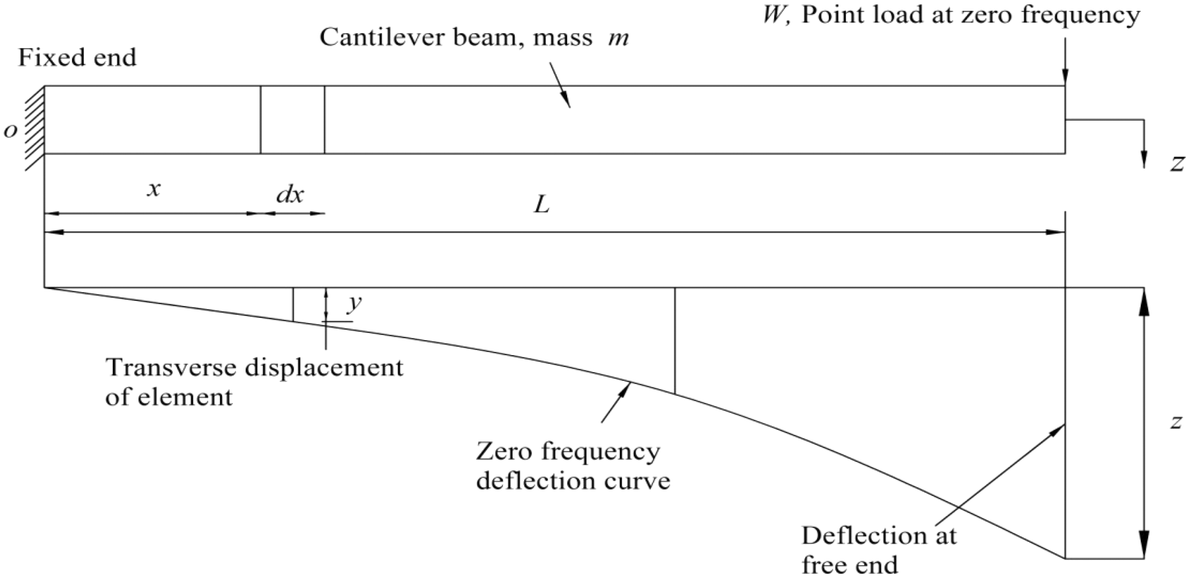
A schematic diagram of an uncracked cantilever beam subjected to zero frequency point load. 11
where K and 0.2357m are the stiffness and the effective mass of an uncracked cantilever beam.
Equation (1) is used to find the natural frequency of uncracked cantilever beam. Then this formula is extended towards the cracked cantilever beam to obtain its stiffness by using a reverse engineering approach.
In this research study, the computed difference between an intact beam mass and cracked beam mass (with largest crack depth) was negligibly small. Therefore, in the vibration analysis (equation (1)), the mass of cracked beams were treated same as the mass (m) of an intact beam.
Vibration method: For obtaining the stiffness of any cracked case by a vibration method (equation (1)), one particular procedure is followed, i.e. initially, the natural frequency for the cracked case of interest is computed by a modal analysis, and then it is substituted in equation (1) to get the stiffness of the same cracked case by using the reverse engineering approach.
Deflection method: For obtaining the stiffness of any cracked case of interest by a deflection method, one particular procedure if followed, i.e. 100 N loads were applied at the free end of a cracked cantilever beam to get its zero frequency deflection in the direction of applied load. Then the stiffness of the same cracked case was computed by using a conventional formula (Stiffness = Load/Deflection or zero frequency deflection).
Simulated crack configurations
In this study, a total of 54 cracked specimens of EN 8 and EN 47 materials were considered in order to investigate the effect of different kinds of open cracks on the stiffness of a cantilever beam.
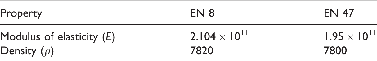
Geometric properties: The length and cross-sectional area of the beam are 0.36 m and 0.02 × 0.02 m2, respectively. The properties of EN 8 and EN 47 material were tested in ELCA Lab, Pune, India and are presented in Table 1.
Material properties of EN 8 and EN 47 spring material.
Two separate crack cases were considered, i.e. case 1 and case 2.
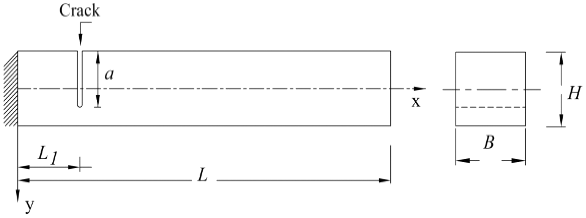
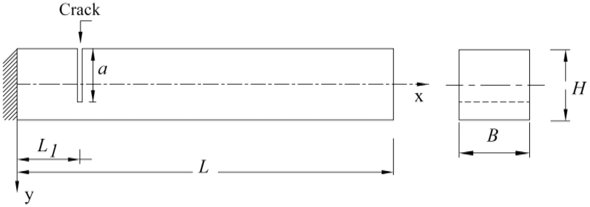
Case 1: In this case, 27 cracked specimens of EN 8 material are considered. This case was subdivided into three subcases. In the first subcase, V-shaped cracked cross section was considered on nine specimens. Of these nine specimens, three specimens carry cracks at 80 mm location, and the next three specimens carry cracks at 160 mm location and the remaining three specimens carry cracks at 240 mm location from the cantilevered end. At these locations, the crack depths were varied from 5 mm to 15 mm with an interval of 5 mm. The case with V-shaped crack is shown in Figure 2. The second and third subcases were similar to the first subcase, with the only difference that instead of V-shaped crack cross section, U-shaped and rectangular-shaped cracked cross sections were considered for the second and third subcases, respectively. The case with the U-shaped crack and the case with the rectangular-shaped cracked are shown in Figures 3 and 4, respectively.

Cracked cantilever beam with V-shaped crack.
Cracked cantilever beam with U-shaped crack.
Cracked cantilever beam with rectangular-shaped crack.
Case 2: Case 2 is similar to case 1, the only difference is that instead of EN 8 material, EN 47 material was chosen for the cracked specimens.
Finite element modeling and analysis
ANSYS 12.1 finite element program was used to determine natural frequency and zero frequency deflection of cracked beams. For this purpose, a rectangular area was created. This area was extruded in the third direction to get the 3D model. Then at the required location, a small rectangular area of required dimensions of crack was created and extruded. Then a small volume of crack was subtracted from a large volume of cantilever beam to obtain a cracked three-dimensional model. The width of the crack is taken as 0.5 mm. For finite element modeling of a cracked beam, solid 95, solid 185 and solid 186 elements were used. Each element gave the same result for the natural frequency and the zero frequency deflections. Hence for all the simulations, 20 node structural solid element (solid 186) was selected for modeling the beam because of the presence of some special features of element, i.e. stress stiffening, large strain, and large deflection. Finite element boundary conditions were applied on the beam to constrain all degrees of freedom of cantilevered end of the beam. The Block Lanczos eigenvalue solver was used to calculate the natural frequencies of cracked beams. Mesh independent study was also carried out to study the effect of mesh size on the natural frequency of cracked beams. In mesh independent study, it was observed that the results of natural frequency were independent of the mesh size. To get the stiffness of a cracked beam, 100 N loads were applied at the free end (tip) of the beam to get the zero frequency deflection. Few natural frequencies and zero frequency deflection plots are shown in Figures 5 to 8.
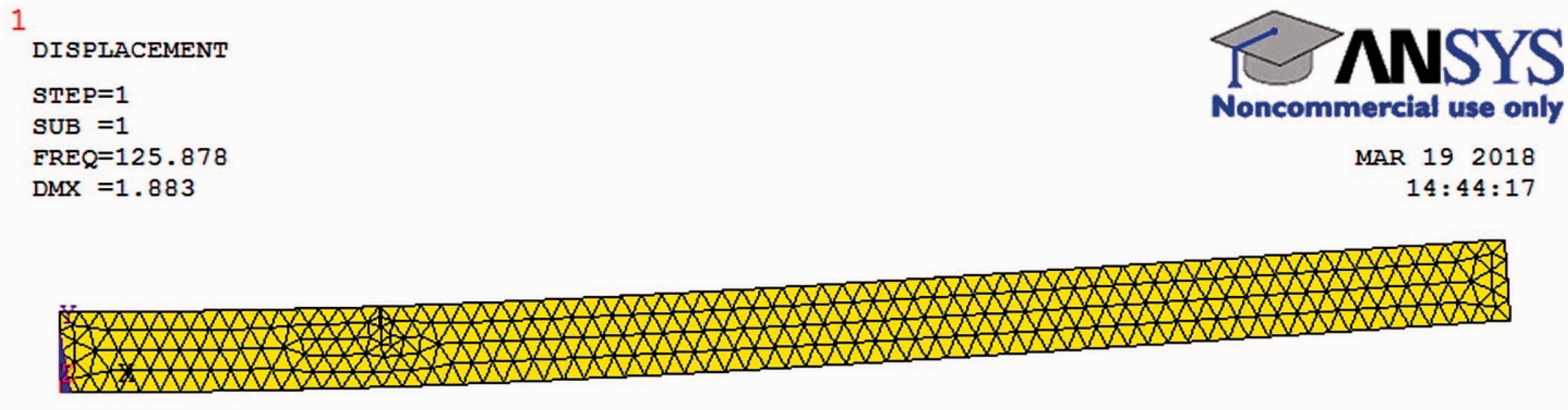
Natural frequency plot: EN 8 V-shaped cracked specimen; L1/L= 0.222; a/H = 0.25.
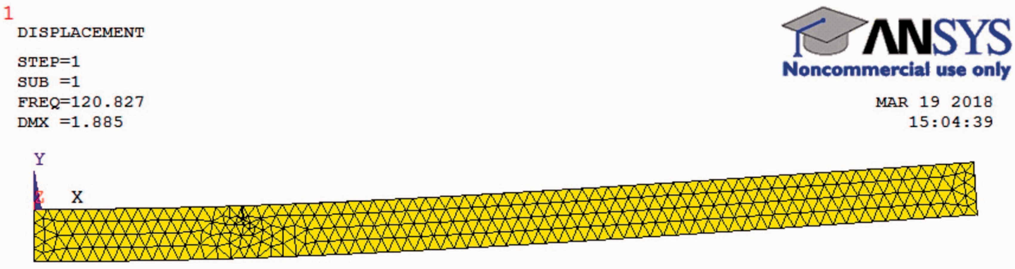
Natural frequency plot: EN 47 U-shaped cracked specimen; L1/L= 0.222; a/H = 0.25.
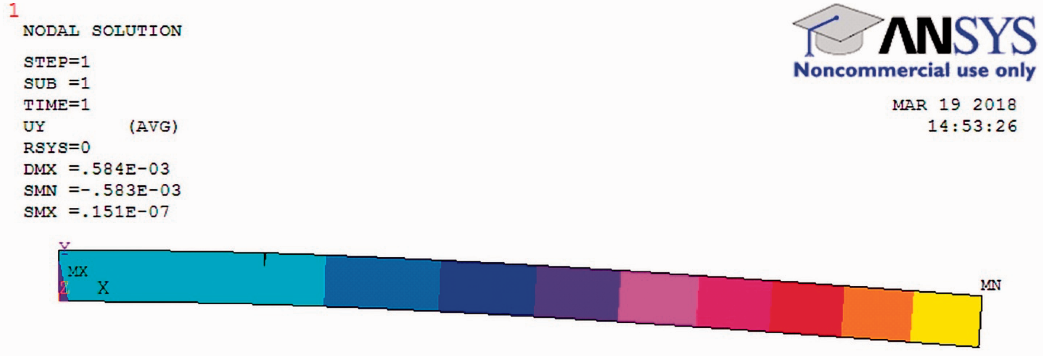
Zero frequency deflection plot: EN 8 V-shaped cracked specimen; L1/L= 0.222; a/H = 0.25.
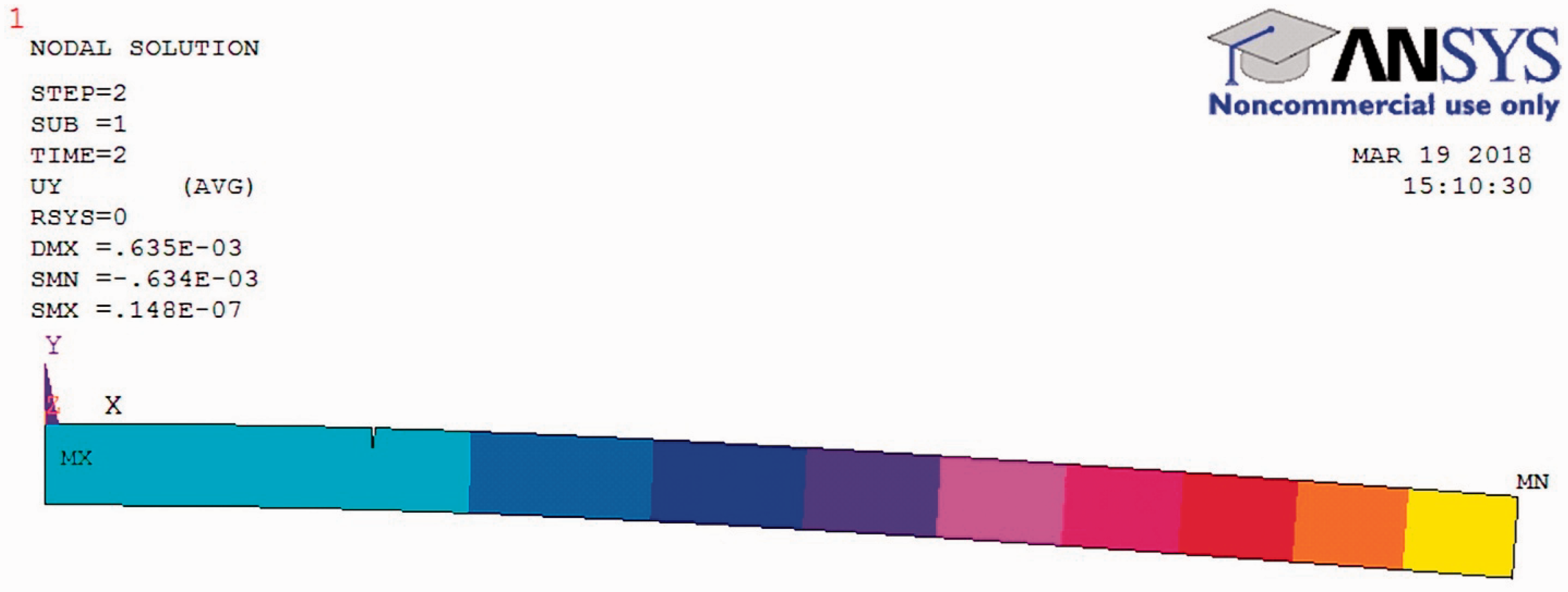
Zero frequency deflection plot: EN 47 U-shaped cracked specimen; L1/L= 0.222; a/H = 0.25.
Results and discussion
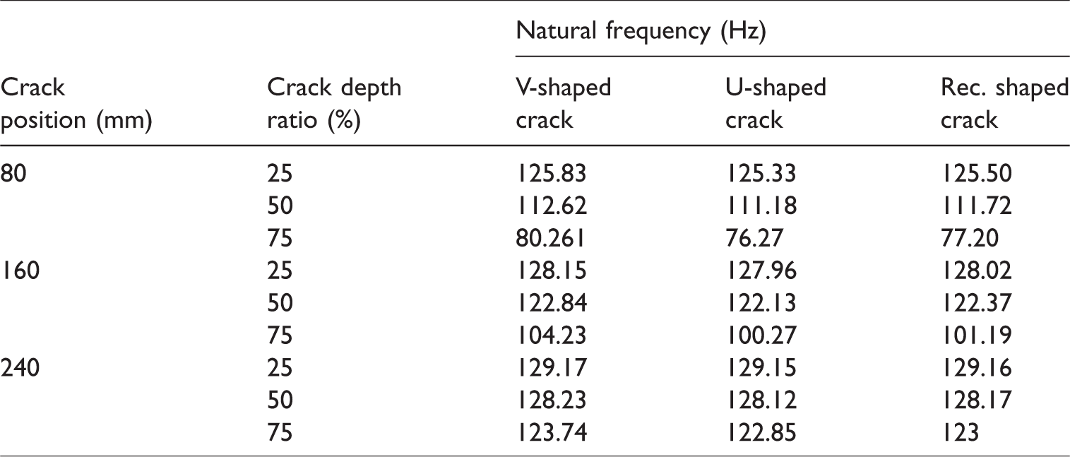
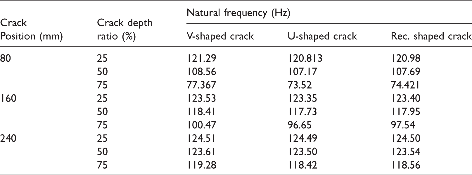
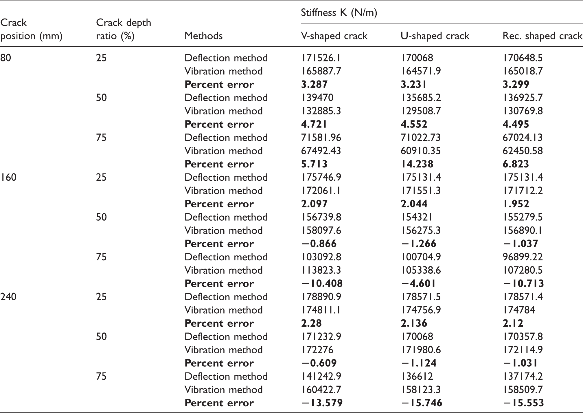
In this study, the stiffness of a cracked cantilever beam that had different crack depths and different crack geometries are investigated by the deflection methods and vibration methods. Then the relationship between different cracked cross sections and stiffness is investigated. Similarly, the relationship between different cracked depths and stiffness, and the relationship between different cracked locations and stiffness are also investigated. The natural frequencies computed by the numerical analysis for EN 8 and EN 47 cracked cantilever beam are presented in Tables 2 and 3, respectively. The results of the stiffness obtained by the deflection methods and vibration methods for the various cracked cases are presented in Tables 4 and 5. The results of the stiffness computed by the deflection methods give some variation with respect to the stiffness computed by the vibration methods due to some changes in the flexural rigidity of the cracked beams. The results obtained by the vibration methods are comparatively more reliable.
The first numerical bending natural frequency of EN 8 cracked cantilever beams.
The first numerical bending natural frequency of EN 47 cracked cantilever beams.
Comparison of the stiffness of EN 8 cracked cantilever beams.
Comparison of the stiffness of EN 47 cracked cantilever beams.
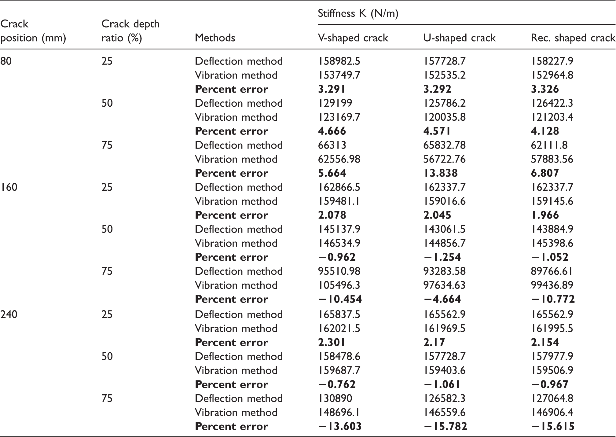
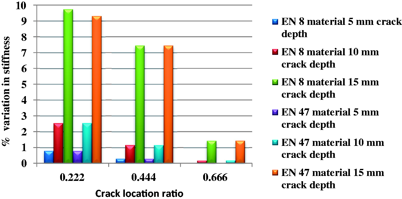
The percentage variation of stiffness between the V-shaped and U-shaped cracked cases with crack location ratio is shown in Figures 9 and 10. From Figures 9 and 10, it is revealed that the percentage variation of the stiffness between the V-shaped and U-shaped crack models is below 10% for all the cracked specimens of steel, EN 8 and EN 47 materials. It means that the variation between stiffness corresponding to change in the crack geometries is only a minor effect. Therefore, it is evident that spring steel materials are slightly sensitive to the changes in crack geometries as long as the vibration characteristics are concerned. The free vibration-based crack detection method uses the effect of stiffness and natural frequencies as a basic criterion for predicting the crack parameters in structures. Hence, this implies that a free vibration-based crack detection method satisfactorily predicts the location and depth of the crack in structures irrespective of the presence of various types of crack geometries, i.e. V-shaped, U-shaped, and rectangular-shaped open cracks.
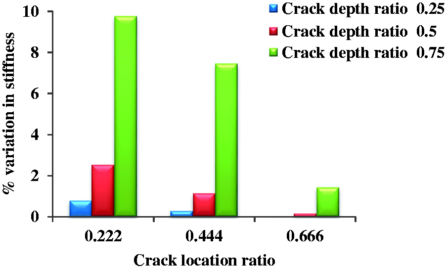
Percentage variation of stiffness between V-shaped and U-shaped cracked models with crack location ratio of EN 8 cantilever beams.
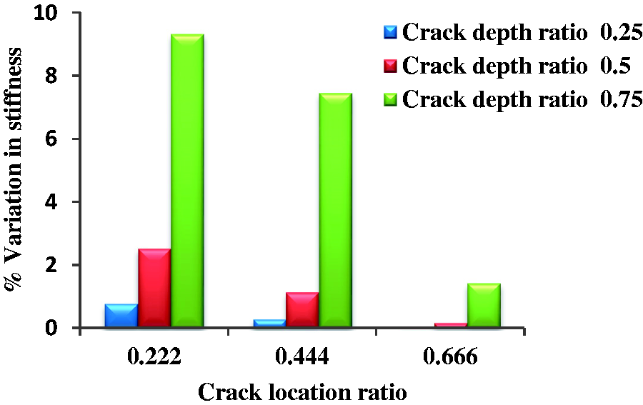
Percentage variation of stiffness between V-shaped and U-shaped cracked models with crack location ratio of EN 47 cantilever beams.
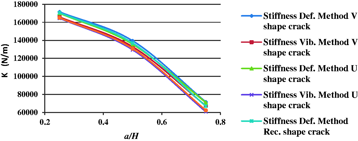
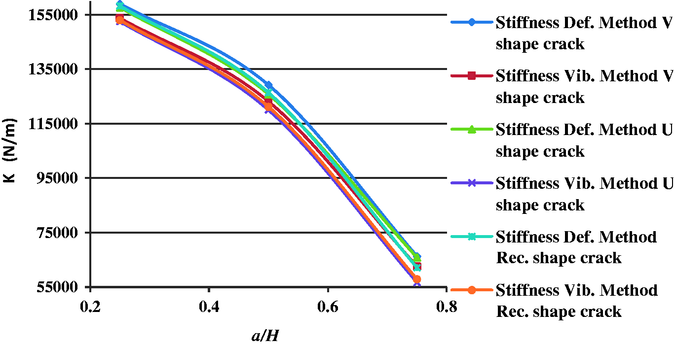
From Figures 11 and 12, it is observed that as the crack depth increases at any unique location, the stiffness decreases for both EN 8 and EN 47 cracked cases of a cantilever beam. It is also observed that the change in dynamic response for U-shaped and rectangular-shaped cracked cases are comparatively more significant than the V-shaped cracked cases for the same configuration. It means that the effect of change in stiffness for the U-shaped and rectangular-shaped cracked cases are comparatively on the higher side than the V-shaped cracked cases with respect to the stiffness of intact beam as shown in Figures 11 and 12. Hence, the free vibration-based crack detection method can efficiently predict the location and size of either U-shaped or rectangular-shaped crack in structures than the V-shaped crack of the same configuration due to the relatively strong vibration signal.
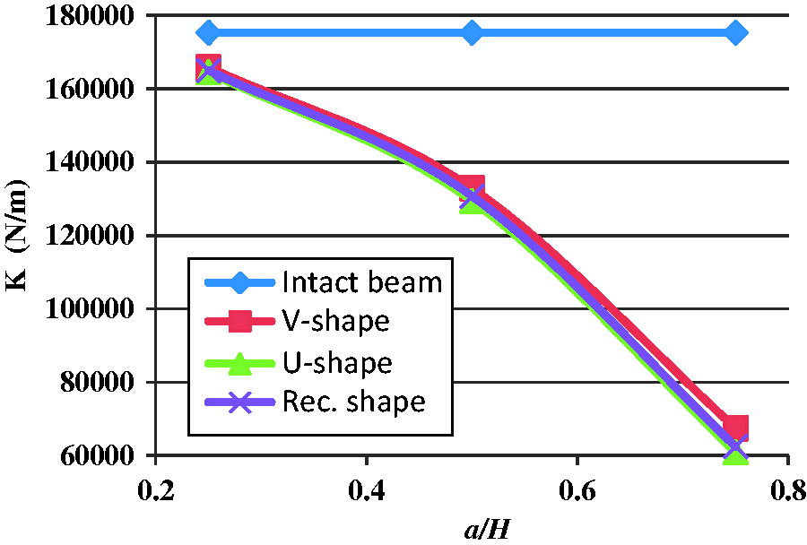
Variation of stiffness with crack depth ratio of EN 8 cracked cantilever beams.
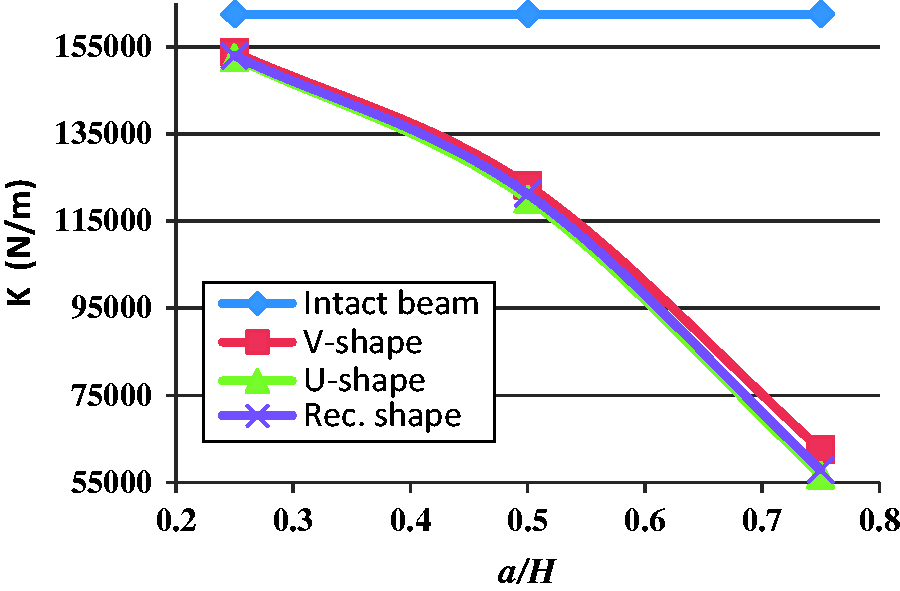
Variation of stiffness with crack depth ratio of EN 47 cracked cantilever beams.
From Figures 13 and 14, it is also observed that at 80 mm crack location from the cantilevered end, when the depth of crack increases, the stiffness of the beam decreases for all the spring steel materials, i.e. EN 8 and EN 47. It is also observed that for all the crack depths, i.e. 5 mm, 10 mm, and 15 mm, the value of stiffness of the U-shaped cracked cases is comparatively on the lower side than the V-shaped and rectangular-shaped cracked cases and this holds true for all the spring steel materials. It means that the results of the cracked beam stiffness are more sensitive to the presence of U-shaped cracks than the other kinds of cracks. For the same crack configuration, the U-shaped cracked specimen gives comparatively less effect of flexural rigidity (EI) in the beam than the V-shaped cracked specimen and rectangular-shaped cracked specimen. This is the reason that the U-shaped crack model gives comparatively less stiffness than other crack models for the same configuration.
Variation of stiffness with crack depth ratio of EN 8 cracked cantilever beam.
Variation of stiffness with crack depth ratio of EN 47 cracked cantilever beam.
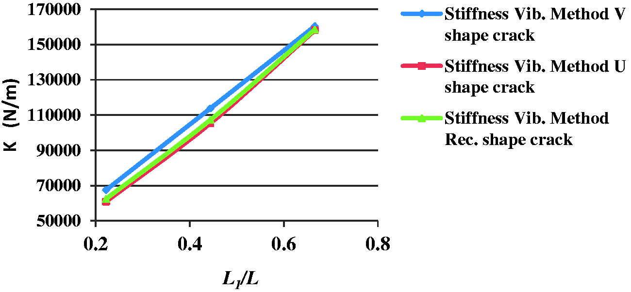
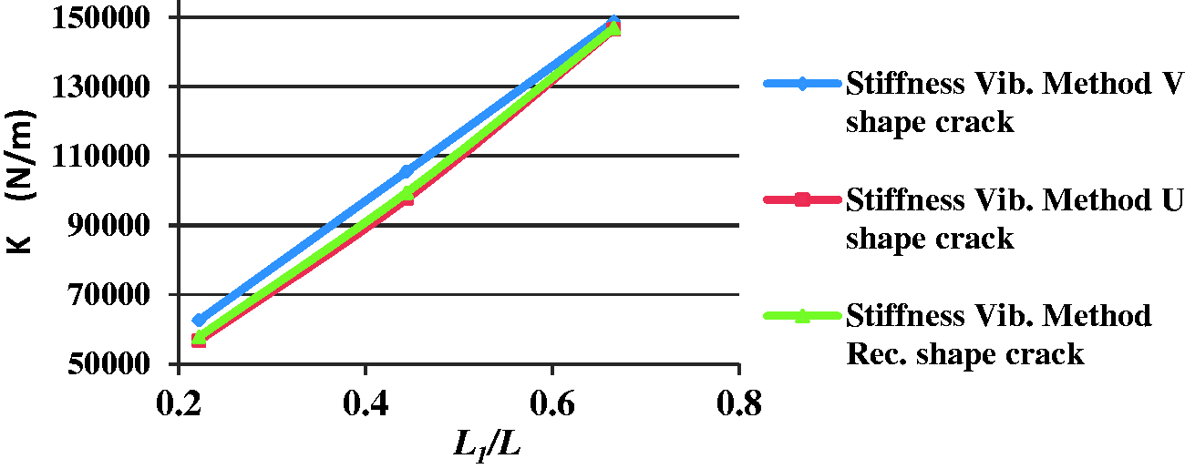
From Figures 15 and 16, it is found that, as crack geometry changes, i.e. V shaped, U shaped, and rectangular shaped, the stiffness of the cracked beam also somewhat changes and this is because of the small changes in the flexural rigidity (EI) of the beam. The change in the stiffness of the cracked beam leads to change in its natural frequency.
Variation of stiffness with crack location ratio of EN 8 cracked cantilever beam.
Variation of stiffness with crack location ratio of EN 47 cracked cantilever beam.
From Figures 15 and 16, it is also found that, when the location of the crack increased from the cantilevered end, by keeping the crack depth constant, then the stiffness increased. The crack which is nearer to the cantilevered end of the beam produces larger bending moment at the crack and on the other hand, the crack which is nearer to the free end of the beam produces less bending moment at the crack. Hence, the stiffness is found to be less for the cracked case in which crack remains nearer to the fixed end and more for the cracked case in which crack remains nearer to the free end of the beam as shown in Figures 15 and 16. It is also observed that for the same configurations, the stiffness of V-shaped cracked model is comparatively on the higher side than the U-shaped and rectangular shaped crack model. This is because of the higher flexural strength of the V-shaped cracked model.
Figure 17 gives the percentage variation of the stiffness between V-shaped and U-shaped cracked cases for the same configurations of EN 8 and EN 47 beams. From Figure 17, it is found that for all the crack depths, i.e. 5 mm, 10 mm and 15 mm, the percentage variation of the stiffness between V-shaped and U-shaped cracked cases remains the same. It signifies that for the same configuration, the structural integrity property or structural stability property of EN 8 and EN 47 cracked cantilever beam remains identical. The same integrity property of a cracked EN 8 and EN 47 beams causes to change its dynamic response by the same amount, i.e. stiffness and natural frequency.
Percentage variation of stiffness between V-shaped and U-shaped cracked models with crack location ratio for EN 8 and EN 47 beams.
Conclusions
By free vibration study, it is possible to diagnose the defects that arise in structures with time. The stiffness of each cracked case of a beam is evaluated by the deflection methods and vibration methods. The computed stiffnesses by a vibration method are in agreement with the deflection method. In this study, free vibration of spring steel-cracked cantilever beams that have different crack-shaped geometries, crack depths, and crack locations are investigated. From free vibration study of a cracked cantilever beam, the following conclusions can be drawn.
Spring steel structures are somewhat sensitive to the change in crack shape geometries as long as the vibration characteristics are concerned. Free vibration-based crack detection method can satisfactorily predict the location and depth of the crack in structures irrespective of the crack geometries, i.e. V-shaped, U-shaped, and rectangular-shaped crack. Free vibration-based crack detection method can more approximately predict the location and size of either U-shaped and rectangular-shaped crack in structures than V-shaped cracks of the same configuration. Vibration monitoring on such structures can be coupled with finite element free vibration analysis in order to determine the severity of damage or defects in such structures. The results of stiffness of cracked spring steel cantilever beams are comparatively more sensitive to the presence of U-shaped cracks than V-shaped and rectangular-shaped cracks of the same configuration. The integrity property or structural stability property of EN 8 and EN 47 cracked cantilever beams are identical as far as the vibration characteristics are concerned. When the crack depth increased by keeping the crack location constant on any spring steel cantilever beam, then its stiffness decreases. At constant crack depth, when the crack location increased from the cantilevered end, then its stiffness increases.
Footnotes
Declaration of conflicting interests
The author(s) declared no potential conflicts of interest with respect to the research, authorship, and/or publication of this article.
Funding
The author(s) received no financial support for the research, authorship, and/or publication of this article.