
Abstract
The flow and acoustic characteristics of underwater gas jets exhausted from large vertical nozzles are experimentally investigated in this work with gas flow rates of 30–150 m3/h, nozzle widths of d = 10 mm, 20 mm, 30 mm, and 40 mm. A high-speed digital video camera is used to examine bubble behavior and flow regimes. Sound pressure is measured by two hydrophones and recorded by a digital audio tape recorder. The audio and video signals are synchronized to find out the relationship between sound and gas behavior. Experimental results indicate that the general behavior of gas exhausted into water is of periodical necking and expansion. Sound pressure peaks are mostly excited by necking in two ways: pinch-off and redial expansion. Necking itself is a kind of low frequency behavior, corresponding to strong low frequency sounds. Moreover, necking can force the growing bubble to oscillate and emit broadband sound. As the gas velocity increases, necking would happen more frequently, and gas jets would grow into larger volume in shorter time, and then the sound radiated from the gas jets would have higher frequency and larger amplitude.
Introduction
Submerged exhaust exists in many industrial applications such as steam generators, sieve tray columns, bio-reactors, aeration, smelting, froth flotation, underwater jet propulsion etc.1–4 The discharging of gas into a liquid can be summed up as two regimes: bubbling and jetting. Gas may radiate different kinds of acoustic signals under these two regimes. Sometimes these signals are very useful. For example, distribution of bubble size in many systems can be obtained by passive acoustic measurements. 5 In some other cases, however, these signals are so harmful that they may make submerged equipment more detectable. 6 Sound radiated by submerged gas jets are closely related to the behavior of gas flow. Therefore, it is an essential issue to understand the relationship between gas flow and acoustic characteristics of submerged exhaust process, especially when using acoustic signal filters or noise suppression.7,8
Acoustic characteristics of underwater gas flow have been of wide concern since the time of Rayleigh. 9 Under bubbling regime, all behavior of bubbles such as detachment, deformation, oscillation, collapse, coalescence etc. can radiate acoustic signals. The characteristic frequency emitted by bubble oscillation with small amplitude has been theoretically predicted and experimentally confirmed,10–12 and this is well known as Minnaert frequency. These results have laid the foundation for many acoustic applications.5,13–15 Choi and Chahine 16 discovered pressure peaks when bubble is splitting, and the noise is correlated with the formation of re-entrant jets in the sub-bubbles. Longuet-Higgins 17 proposed radial liquid -inrush, when pinch-off occurred, could impart acoustic perturbation to the bubble. Manasseh et al. 18 found that bubbles coalescing on formation could generate loud bubble-acoustic emissions at the instant of coalescence of secondary bubbles with the primary bubble, and the amplitude of the emitted sound was up to an order of magnitude greater than the sound created on pinch-off of the primary bubble. Furthermore, the interactions between bubbles cannot be ignored when the amount of bubbles is large. Harkin et al. 19 presented and analysed a model for spherical pulsations and translational motions of a pair of interacting gas bubbles in an incompressible liquid. They showed that under weak acoustic forcing conditions, the radial pulsations of the bubbles were weakly coupled, which allows a nonlinear time-averaged model for the relative distance between the bubbles. Manasseh et al. 20 studied the sound field generated by a bubble chain, and developed a preliminary theoretical model using a linear coupled-oscillator approximation in order to explain the anisotropy field of the sound. Deane and Stokes 21 analysed experimentally and theoretically the acoustic excitation mechanism of bubble fragment in sheared fluid flow. They predicted the bubble pulse amplitudes using the proposed model based on symmetric collapse of the neck of air joining fragmentation, and the predicted results were in conformity with the experimental results. The acoustics of bubble clouds were also studied by Nicholas et al., 22 and bubble plumes were found to be a major source of underwater sound with frequencies to a few hundred hertz. In summary, the sound radiation mechanism of single bubble has been well studied for a long time. In recent years, many researchers have focused on sound radiated by multiple bubbles. However, these studies are still limited to simple cases. Further study is needed to get better understanding of acoustic characteristics of bubbles under complex exhaust conditions.
At high gas flow rates, the flow regime will change from bubbling to jetting. Under this condition, the acoustic field radiated by the turbulent two-phase flow cannot be easily predicted. Thus, most of the research works have mainly considered experimental investigations. Gavigan et al. 23 experimentally studied the noise generated by submerged gas jets, and their results indicated that radiated noise was primarily a function of orifice radius, turbulence parameters and only secondarily of gas flow rates. Chen et al. 24 found that orifice size played an important role in noise generation; however, when gas velocity exceeded a threshold, the noise in an important frequency band would increase regardless of the orifice size. Arghode and Gupta 6 studied characteristics of underwater gas jets with respect to nozzle cross-section and jet momentum for air–water and helium–water system, and illustrated that sound pressure level for elliptical nozzle was lower than that of circular, square, and triangular nozzles. Xu et al. 25 studied the sound spectrum generated by steady gas jet from a submerged horizontal nozzle, especially the effects of gas velocity in the range of 35–140 m/s on the sound spectrum. The results indicated that increasing gas velocity would elongate and strengthen bubbles, as well as increase acoustic emission. Li et al. 26 studied the effects of gas production on the acoustic radiation characteristics of underwater pyrotechnic combustion. They found that the sound pressure level would increase with the gas production. Miao et al. 27 studied the flow and acoustic characteristics of submerged exhaust through a lobed nozzle. They found that nozzle structure has important effect on the submerged exhaust noise. In summary, the acoustic signals generated by underwater gas jets are mainly dependent on gas velocity and nozzle structure, and are further dependent on dynamic behavior of bubble group. However, how does sound radiate from underwater gas jets is not yet comprehensively clarified in most of the studies mentioned above.
Current research achievements on submerged exhaust are greatly attributed to chemical industrial applications. As these studies are mainly concerned with the performance of chemical equipment such as bubble columns, sieve trays, etc., the orifices used in these researches are usually hundred-micron-sized or millimetre-sized. Clift et al. 28 have summarized the formation of bubbles caused by flow at modest flow rates through orifices of diameter less than 6.5 mm. Gulawani et al. 29 gave a review of studies on submerged exhaust, and most experiments were done with nozzles of diameter less than 10 mm. Some other relative studies which concern both the flow and acoustic characteristics of submerged exhaust were also done with millimetre-sized nozzles and low gas flow rates.30,31 However, gas discharged from underwater equipment, which primarily comes from the engine, normally has large volume flow rates, and the diameters of the exhaust nozzles are usually several centimetres. As mentioned above, the diameter of the exhaust nozzle is an important factor that would affect the acoustic characteristics of gas jets. It is highly necessary to do experiments in larger range of nozzle sizes and various gas flow rates, in which they are more suitable for cases of submerged exhaust by underwater equipment.
In this paper, large diameter (10–40 mm) vertical nozzles in a water tank are used to study underwater gas behavior at gas flow rates of 30–150 m3/h. As few studies have been reported in these operating conditions, gas behavior will be described in detail. Then the common regularity of gas behavior from bubbling to jetting is summarized, and relative data are analysed. To find out the sound sources of submerged exhaust, the synchronization of audio and video signals is analysed. The sound radiation mechanisms are revealed, and relative influential factors are discussed. Finally, the sound spectrum is analysed to validate the derived inferences and conclusions. The results obtained reveal the flow and acoustic characteristics of gas jets with a wide range of gas flow rates from nozzles of large diameter.
Experimental setup and conditions
A schematic of the experimental layout is shown in Figure 1. The size of the water tank is 3 m × 1.5 m × 1.5 m. Water depth in the tank is 1.2 m. The volume of the air tank is 0.8 m3. Compressed air is stored in the air tank as gas source. A pressure control valve and a throttle valve are arranged in the pipeline to adjust the gas flow rate and make it stable for a long time. Gas pressure after the pressure control valve is 0.2 MPa. The exhaust nozzle of 100 mm length was placed in the water tank vertically, with its orifice being 0.6 m below the water surface, see Figure 1(b). The water used in this experiment is ordinary tap water.
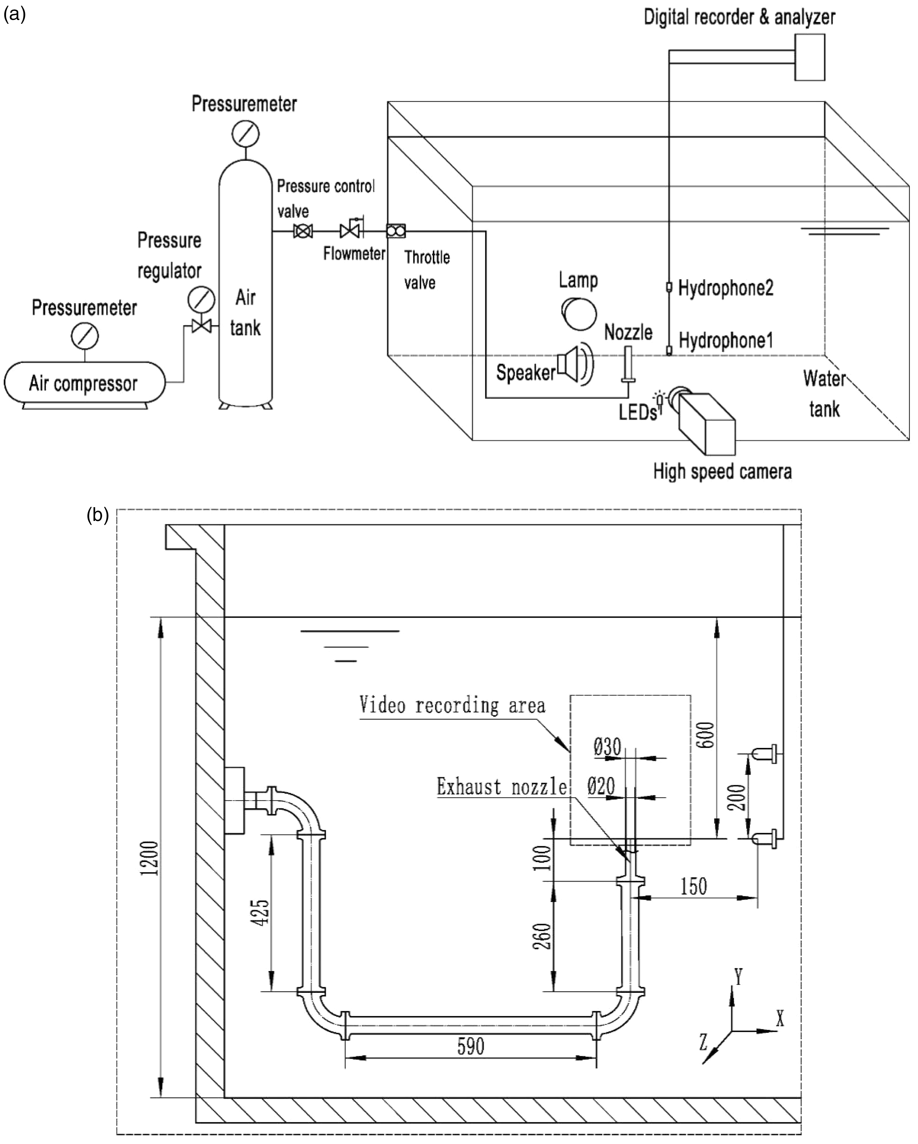
Schematic of the experiment, (a) overall layout; (b) detailed sizes.
Two Reson TC4040 type hydrophones are arranged in the water. Considering a coordinate system as shown in Figure 1(b) with the nozzle orifice centre set as the origin point (0, 0, 0), the hydrophone 1 is placed at (150, 0, 0), and hydrophone 2 is placed at (150, 200, 0). Sound pressure signals are recorded continuously for 10 s using a digital audio tape recorder. According to the Nyquist Theorem, the sampling rate must be more than twice the maximum frequency component of the signal being measured. The bubbles with a wide range of sizes in the experiment would emit broadband sound. The sound is measured with frequencies lower than 10 KHz with a 20.48 KHz sampling rate. Linear weighting is used in acoustic measurement for signal pre-processing.
A NAC Memrecam HX-3 high-speed digital video camera is used to record gas behavior at a frame rate of 500 Hz with exposure time of 1 ms. The image region, 282 mm width and 353 mm height, is described by 768 × 960 pixels, and the film can be recorded over 20 s under such settings. One 80 W halogen lamp is placed behind the exhaust nozzle, and a sheet is placed between the lamp and the nozzle to distribute light evenly over the test section. The exposure conditions would be different as the gas flow rate changes, so that parchment papers with 1–4 layers are used to adjust the lighting source.
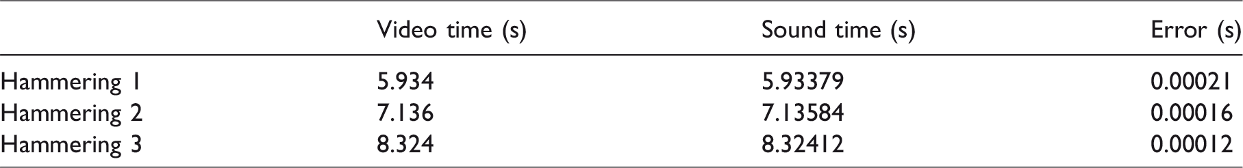
Uncertain delay occurs when audio tape recorder and camera are triggered. In order to synchronize the audio and video signals, a speaker and an LED are used. The speaker was placed below hydrophone 1, and the LED was placed at the observation window of the water tank in front of the video camera. At the end of each test, the speaker and the LED were activated by a 2 KHz sine signal for a while, and brought close together as a synchronized calibration. Figure 2 shows a synchronous error test. Hammerings are made three times at a pipeline, and the video and audio signals record, then these signals are synchronized using the method mentioned above. The moment when the signal generator is closed is the synchronizing point. At this moment, it can be seen from the video that the LED suddenly became very bright (Figure 2(b)) and found an obvious sound peak in the sound signal (Figure 2(c)). This moment is set as the time origin of the video and the audio, and it can be seen from Table 1 that the video times and the audio times of the three hammerings were very close to each other. The synchronization error of this method was less than 2 ms.
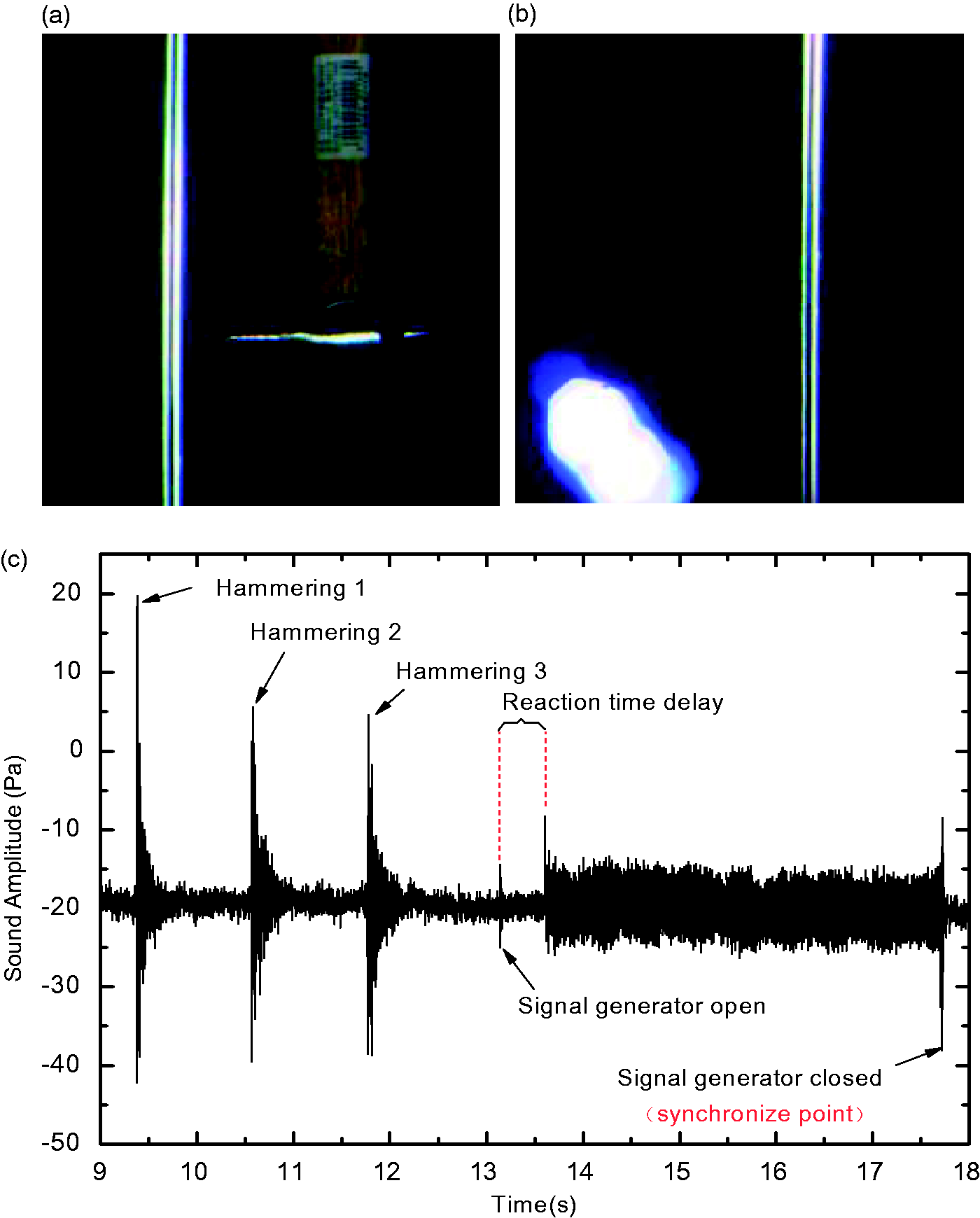
Synchronous error test, (a) the moment of hammering 1; (b) image of the synchronize point; (c) sound signals in time domain.
Synchronous test results.
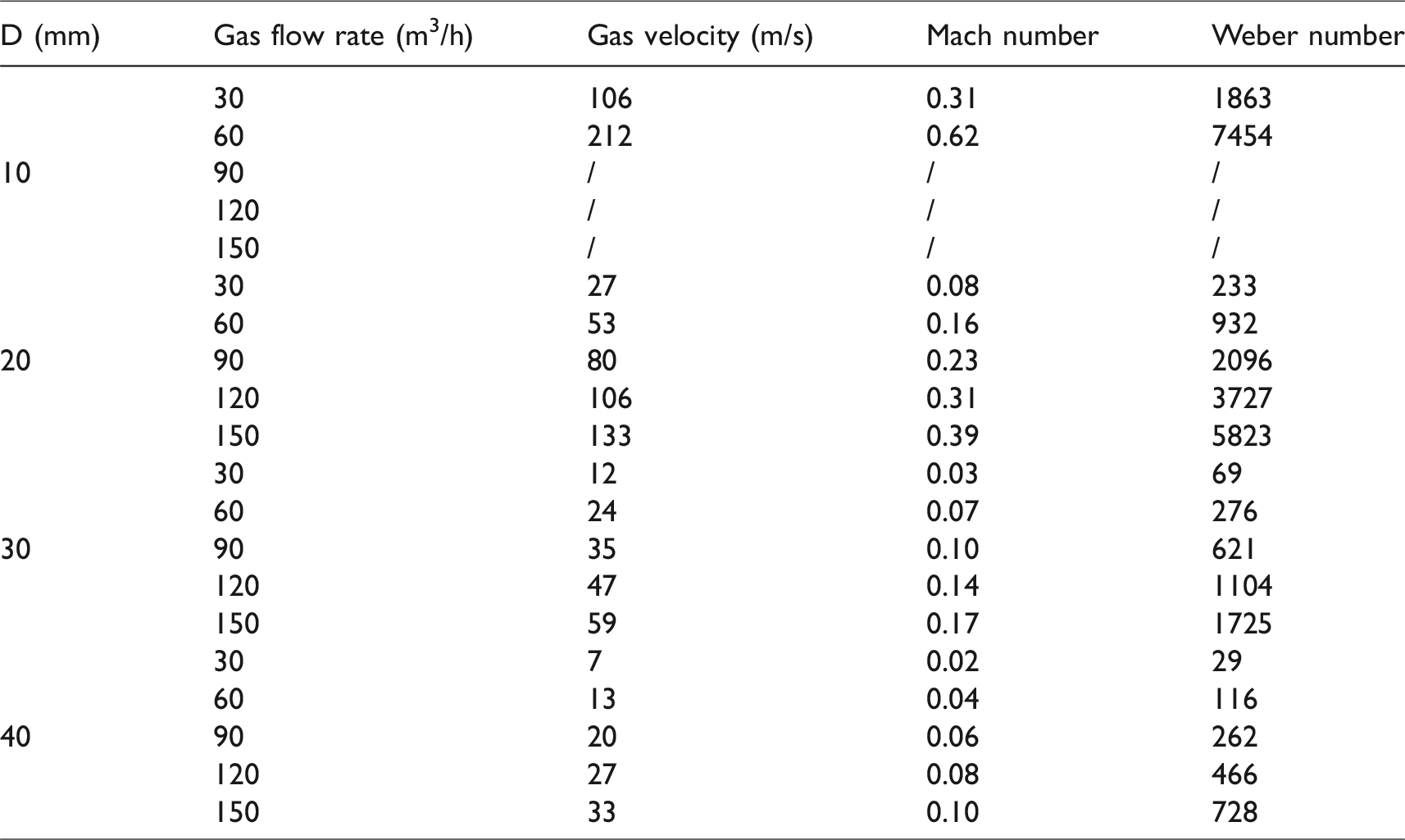
Nozzles with circular cross-sections of d = 10 mm, 20 mm, 30 mm, and 40 mm are used in this work. All these nozzles are made of stainless steel with thickness of 5 mm. Gas flow rate is chosen as the control parameter. Experimental conditions are summarized in Table 1. It is worth noting that under the condition of d = 10 mm and Q > 90 m3/h, the gas velocity calculated by Q/A (A is the cross-sectional area of nozzle exit) is transonic and supersonic, but the actual gas velocity cannot reach that high when the nozzle is straight. As only gas flow rate is measured in this experiment, the gas velocity under these conditions could not be converted by other parameters, hence not listed in Table 2.
Experimental conditions (under standard pressure, 15°C).
Experimental results and discussion
Gas flow behavior
Submerged gas flow can possess either bubble or jet like behavior based on the momentum of gas-phase. Weber number is a dimensionless number which can be thought of as a measure of the relative importance of the fluid's inertia compared to its surface tension, written as
At low gas flow rates, bubbles are generated in pairs periodically; the typical process is shown in Figure 3. Initially, the first bubble (generated formerly) grows in approximately spherical shape. As it rises up, the bubble base detaches from the nozzle and tends to be closed up gradually. Meanwhile, the obstructed upstream gas flow would expand radially to blow the first bubble, which would lead to a depression and destruction of the bubble base. When the bubble base is destructed, liquid would be brought into the first bubble in form of droplets, and the first bubble would connect with the upstream gas again (Figure 3 at 119 ms and 143 ms respectively). The newly formed connection channel with approximately cylindrical shape, which was called “stem” by Wraith and Chalkley, 33 is easy to break and would coalesce into the first bubble rapidly. Then the first bubble would freely rise up. The generation of the secondary bubble (generated second) is similar to that of the first bubble (at 202 ms). However, the secondary bubble grows faster along the axial direction (i.e. Y direction shown in Figure 1(b)) since it is affected by the entrainment effect of the first bubble, and would approach to the first bubble. When the two bubbles are connected, the gas in the secondary bubble would flow into the first bubble rapidly, manifesting suddenly increasing axial-velocity and radial shrinkage of the secondary bubble (at 267 ms and 276 ms correspondingly). The secondary bubble would soon collapse when it detaches from the nozzle, as the inrush of liquid from the bubble base would disintegrate its unstable envelope. After then, the first bubble with lots of droplets would collapse into bubble clouds (at 300 ms). The entrainment effect of the bubble clouds, which is not obvious, cannot influence the newly formed bubble. Thus, newly formed bubble would generate in similar form to the first bubble, then a new cycle starts.
Typical behavior of gas exhaust from underwater vertical nozzle (d = 40 mm, Q = 30 m3/h; time-intervals shown in milliseconds).
The periodical phenomenon mentioned above sometimes may be unstable. If the first bubble has already risen a long distance from the orifice, while the secondary bubble just begins to generate, the secondary bubble cannot be affected by the first bubble, and the second would act as a new first bubble, or it would be affected so slightly that it would grow into drop shape and not collapse soon, then a stem would generate immediately (In general, the stem will not appear after the secondary bubble, see Figure 4). These unstable situations would happen at all gas flow rates (see Figure 6). At low gas flow rates, these situations just happen occasionally and would recover after a few cycles. At higher gas flow rates, gas behavior is similar to the typical mode, but the instability mentioned above will increases. This would be further discussed in the next section.
Instability of the periodical phenomenon (d = 30 mm, Q = 90 m3/h; time-intervals shown in milliseconds).
With flow rate further increasing, the gas flow becomes more continuous. Under this condition, independent bubbles are rarely seen near the nozzle exit, and the flow regime keeps jetting. However, gas behavior is still similar to the typical process described above. Gas would expand radially when it flows out from the nozzle and form a gas bag. As the gas bag rises up, necking happens near the nozzle exit. The obstructed upstream flow would break the base of the gas bag and bring liquid droplets into it. Then another expansion happens. Therefore, it is very interesting to see that the processes of bubble flow and jet flow are essentially the same. The jet flow can be treated as a continuous bubble chain. Then the bubbling-to-jetting transition process can be described as follows: with gas velocity increasing, bubble would be stretched along the axial direction (Y direction) due to three factors: (1) increased gas momentum along the axial direction; (2) stronger entrainment effect of the former bubble; (3) entraining of droplets and small bubbles due to the easier broken gas-liquid interface. In this way, the newly formed bubble would connect with the former bubble more easily with higher gas velocity and eventually form a continuous flow.
Regularity of necking and expansion
As discussed above, there are some regularities for submerged exhaust between low and high gas flow rates through large size nozzles. That necking can always happen when bubbles (or gas bags) detach from the nozzle, and pinch-off could be treated as one kind of necking phenomenon. When necking happens, axial flow would be obstructed and then gas would expand radially (see Figure 5). These expansions could be treated as pulse volume sources which could radiate sound pressure. Thus, more attention has been paid on the regularity of necking and expansion phenomena. Here necking means the moment when upstream gas no longer flows into the former bubble (e.g. 119 ms in Figure 3), after this moment a new bubble would begin to expand until the next necking happens (e.g. 119–162 ms in Figure 3).
Similar gas behavior under different exhaust conditions.
Since time intervals between two adjacent necking can reflect the expansion time (at low gas flow rates, it is the bubble growth time), they have been extracted and typical cases are shown in Figure 6. At low gas flow rates, each cycle consists of a first bubble, a stem, and a secondary bubble in sequence as mentioned above (Figure 6(a)). Growth time of these kinds of expansions is relatively stable in each cycle. Although several non-periodic data exist in the results (Figure 6(b)), reflecting the instability discussed in the previous section, the gas behavior is still cyclical in most of the time. As gas flow rate increases, it is hard to distinguish the first bubble or the secondary bubble in growth time (Figure 6(c)). This is because the interaction between bubbles is so strong that the first bubble could be affected by primary bubbles, and it grows in a similar way like the secondary bubble, and reciprocally, the secondary bubble with a stem accompanied would grows more like the first one. That would lead to an occasional connect of multiple bubbles (like the secondary bubble connecting with the first bubble). At much higher gas flow rates, single bubbles are rarely seen and the flow regime is jetting (Figure 6(d)). The process under this regime could be summarized as main-secondary pulses. The main pulses which have longer expansion time behave similarly to the secondary bubbles, and the secondary pulses which have shorter expansion time behave similarly to the stems. The duration of each kind of pulse is relatively stable in a range.
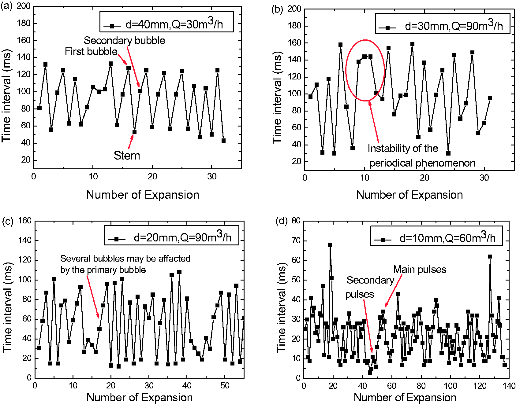
Time intervals between adjacent necking phenomena (The abscissa represents the number of expansion, the ordinate represents time interval between two adjacent necking, namely, the expansion time). (a) d = 40 mm, Q = 30 m3/h; (b) d = 30 mm, Q = 90 m3/h; (c) d = 20 mm, Q = 90 m3/h; (d) d = 10 mm, Q = 60 m3/h. Here, d presents the diameter of the nozzle exit, and Q presents the gas flow rate (already mentioned in the preceding paragraghs).
As shown in Figure 7, necking locations distribute randomly even at low gas flow rates. Under a certain condition, necking appears randomly in certain ranges, which would affect the bubble interaction and further lead to the instabilities mentioned above. Necking usually happens at position s/r = 0.5–2 above the nozzle orifice, where s is the distance of necking away from the nozzle exit, and r is the nozzle radius.
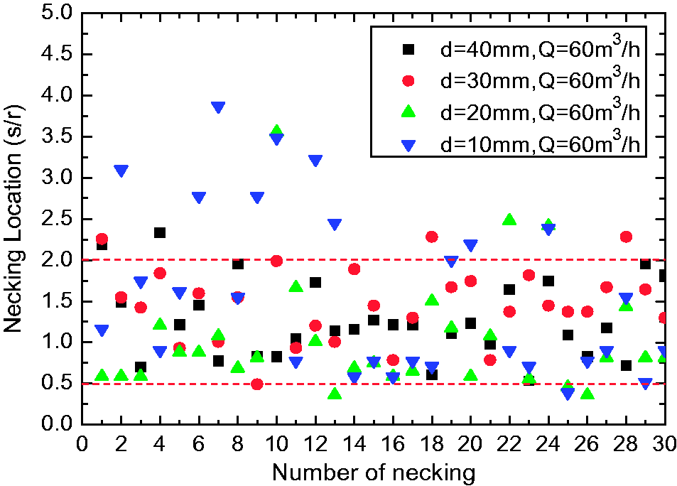
Necking location is random in range of s/r = 0.5–2.
The first, second bubble and the main pulse are taken as main expansion, the stem and the secondary pulse as secondary expansion. The average time of each kind of expansion under different test conditions has been extracted (Figure 8(a) and (b)), and then the bubble volume calculated (Figure 8(c) and (d)). When studying the bubble formation under constant flow conditions, Clift et al.
28
has proposed the dimensionless bubble volume as
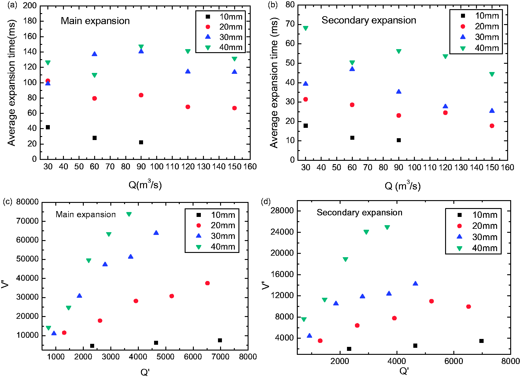
Average expansion time and bubble volume under different exhaust conditions. (a), (b) The average expansion time of the main expansions and the secondary expansions. (c), (d) Variation of dimensionless bubble volume with dimensionless gas flow rate.
The average time of bubble expansion depends on the speed of bubble detachment. Generally, smaller nozzle size and higher gas flow rate (higher axial gas velocity) would lead to faster detaching from the nozzle. This is reflected in Figure 8(a) and (b). It seems that the nozzle size affects the average expansion time much more than the gas flow rate. Bubble detachment from larger size nozzle would take longer time, because the nozzle size would affect the contact angle and the surface tension. For these reasons, the bubble volume would also increase with nozzle size. With higher gas flow rates, the average expansion time decreases but the bubble volume increases. This result indicates that, as gas velocity increases, the necking and radial expansion would happen more frequently, and bubble would grow into larger volume in a shorter growth time. This means a larger volume pulse rate which would radiate louder sounds.
Acoustic sources
It should be noted that all sounds are produced by oscillations. In submerged exhaust situation, it is the oscillation of the gas–liquid interface producing sound. Under bubble flow regime, it has been well known that the main acoustic sources are bubbles. Longuet-Higgins34,35 has proposed three mechanisms to explain how bubble oscillations set in motion: (1) instant pressure changes inside the bubble; (2) radial inrush of liquid as pinch-off occurs; (3) nonlinear interactions between the “breathing” mode and the shape modes oscillations. 18 Various kinds of bubble behavior that can cause bubble oscillation have been studied. These include break-neck, 36 coalescence, 18 bubble fragmenting, 37 and liquid cross-flow. 38 These situations can be mostly explained by the mechanism proposed by Longuet-Higgins.34,35 Under jet flow regime, independent bubbles are rarely seen near the nozzle exit, but can be seen at the downstream places. Some researcher thought sound is mostly emitted downstream by the bubble coalescence and fragmenting.23,24 However, further investigations are still needed.
If acoustic signals could be associated with the corresponding gas behavior, the sound could be controlled accordingly. To find the acoustic sources, image data should be processed firstly. As observed in Section “Regularity of necking and expansion”, necking usually happens at position s/r = 0.5–2 above the nozzle orifice, thus the bubble width is measured at s/r = 2 using the photographic measurement method proposed by Weiland. 39 Comparisons between the image processing results and the time domain acoustic signals are shown in Figure 9.
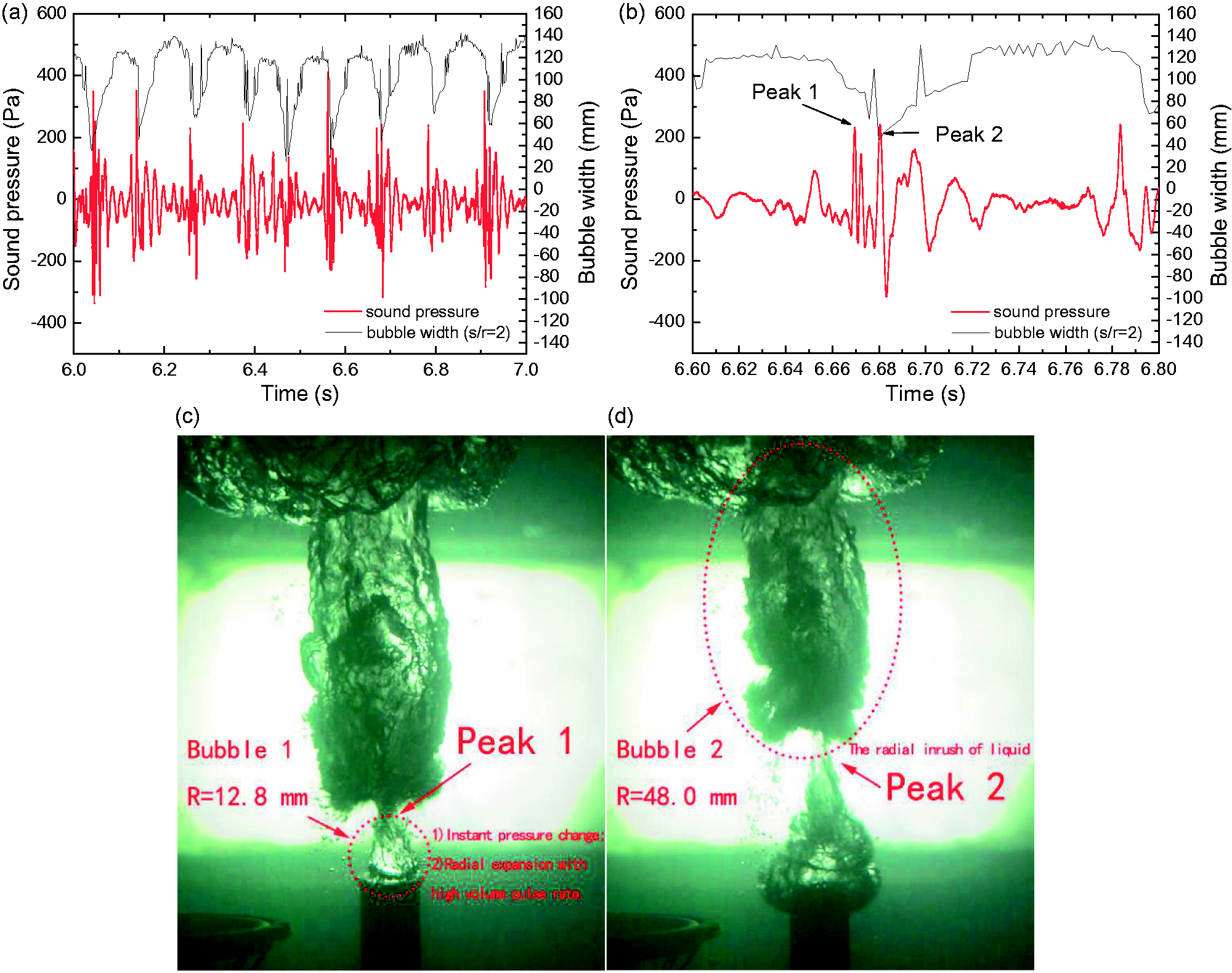
Comparison of the synchronized audio and video signals (d = 20 mm, Q = 60 m3/h, sound pressure data from hydrophone 1). (a) synchronized sound pressure and bubble width near the nozzle exit; (b) partial enlarged detail of (a); (c) the moment of necking; (d) the moment of bubble pinch off.
As shown in Figure 9(a), strong acoustic signals obviously correspond to the emergence of necking. More details can be seen in Figure 9(b) where there are two sound peaks accompanied with different frequencies of sound. When estimating the oscillation frequency, one can use the equation proposed by Minnaert,
10
expressed as
In Figure 9(d), pinch-off happens and radial inrush of liquid can be observed. This means that bubble2 is forced to oscillate due to the pinch-off mechanism proposed by Longuet-Higgins.34,35 While in Figure 9(c), necking occurs instead of pinch-off. In this situation, the gas flow would be obstructed, and this would cause the pressure inside bubble1 to increase rapidly. In this way, bubble1 might be forced to oscillate by mechanism (1): the instant pressure changes inside the bubble. Meanwhile, it is observed that bubble1 suddenly expands radially at the moment shown in Figure 9(c) which could be regarded as strong pulse volume source. Sound pressure emitted by this kind of source could be expressed as
25
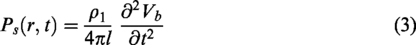
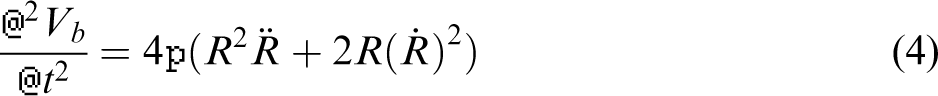
When gas velocity is high enough, the flow regime would convert into jetting. Pinch-off would rarely be seen, but necking always occurs accompanied by strong radial expansion and radiates loud sound. As the interface is hard to be distinguished, bubble width cannot be measured. However, the relationship between necking and sound pressure peak can still be seen from Figure 10. It has been noted that sound radiation by gas jets due to this mechanism has not been considered before. If the time domain process of the radial expansion near the nozzle exit can be described theoretically, then the sound pressure could be calculated using equations (3) and (4). However, no suitable theoretical model has been built up for this situation, thus further work is still needed.
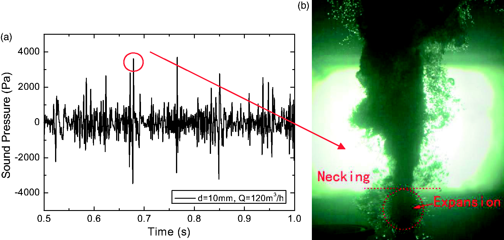
Sound pressure peaks in jetting regime (d = 10 mm, Q = 120 m3/h, sound pressure data from hydrophone 1). (a) sound pressure curve in time domain; (b) necking and expansion near the nozzle exit.
Influential factors
As discussed above, underwater gas jets would emit sound by two mechanisms depending on whether pinch-off occurs or not. “No linking” time, which was proposed by Ozawa and Mori, 40 is the period of time between the severance of the first bubble from the gas supply and the subsequent linkage of the severed bubble to the forming of second bubble. They defined that when the ratio of the sum of “no linking” time to the total time is lower than 30%, then flow regime can be regarded as jetting. In this paper, process all the videos are processed into binary figures, in which water would be expressed as 0 and gas would be expressed as 1. 39 If some lines in a figure were filled with 0, it means this zone is filled with water, hence the gas flow was not linked at this moment. In this way the no linking time of each experiment can be extracted. This theory is helpful to specify the kind of mechanisms with which sound is radiated under certain conditions.
The relationship between “no linking” time fraction and gas velocity is illustrated in Figure 11. Ozawa and Mori 40 has reported that the size of orifice has minor effect on the time fraction using orifices with diameters of 2, 3, and 4 mm. It is found that this conclusion is consistent with larger nozzles (20–40 mm). “No linking” time decreases with increasing velocity, which means that the flow regime is more continuous and pinch-off occurs less often. This result indicates that most sounds would be excited by radial expansion mechanism (Figure 9(c)) in jetting regime.
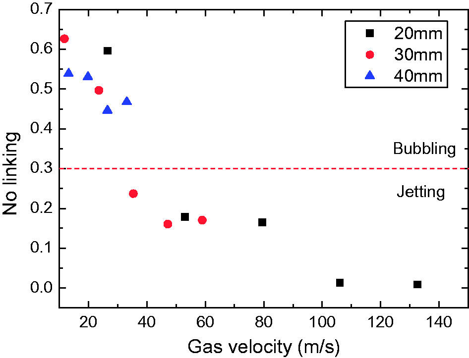
Time fraction for “no linking” time” plotted against gas velocity.
Average peaks of sound pressure under different conditions are summarized in Figure 12. It can be concluded that sound pressure amplitude would increase positively with gas flow rate, and negatively with nozzle size. The average sound pressure peak in d = 10 mm is much higher than other cases. It might be explained that as the gas velocity is higher and the initial bubble radius is smaller under this condition compared with others (see Table 2 and Figure 8), this leads to a higher instantaneous volume acceleration in equation (3). Moreover, the nozzle used here is straight nozzle, thus gas velocity would no longer increase with increasing gas flow rate, when it approaches the speed of sound. This means that gas would be in the state of under-expanded. Then it would make the gas to release more energy when it is exhausted from the nozzle, and hence it radiates larger amplitude sound pressure.
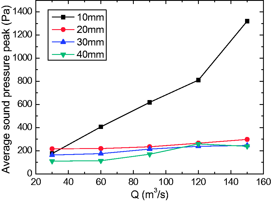
Average sound pressure peaks under different conditions. (a) d = 40 mm. (b) d = 30 mm. (c) d = 20 mm. (d) d = 10 mm.
Sound spectrum
Sound spectrum is very helpful in acoustic analysis as it could give an overall understanding of the acoustic characteristics of underwater gas jets. The two hydrophones used in the experiment show the same trend, and the data used to analyse below are from hydrophone 1, which is closer to the nozzle exit. Sound spectra under different conditions are shown in Figure 13.
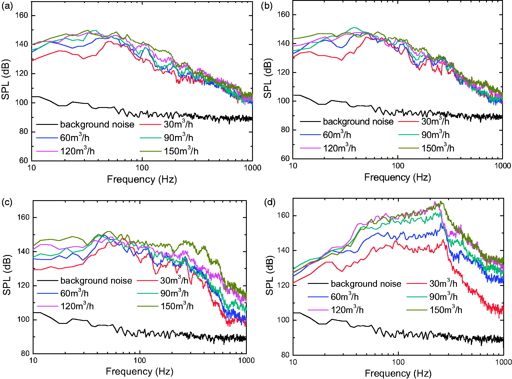
Sound spectrum under different conditions.
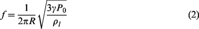
As discussed above, necking would excite sound pressure peaks and force the growing bubble to emit broadband sound. The statistical results of necking and expansion phenomena in Section “Regularity of necking and expansion” indicate that necking is a kind of low-frequency behavior. This may explain why low frequency sound in Figure 13 is always strong. At higher gas velocity, necking happens more frequently, and the peak frequency tends to become higher. As shown in Figures 8(c) and (d), bubble volume would be smaller with smaller nozzle size. This means that the sound spectrum emitted by bubble oscillation would move to higher frequencies (see equation (2)). Sound pressure level with d = 10 mm nozzle is obviously higher than those with larger nozzles, due to the reasons discussed in the previous section. In summary, necking plays an important role in underwater gas jets. The sound spectrum is closely related to the regularity of necking phenomenon.
Conclusion
This paper has investigated the flow and acoustic characteristics of underwater gas jets exhausted from vertical large diameter (10–40 mm) nozzles. The main aim has been to find the relationships between sound signals and gas behavior of underwater gas jets. Experiments are accomplished with four sizes of nozzles and different gas flow rates. The principal conclusions are as followed:
Gas exhaust into liquid has similar behavior with different nozzle sizes and gas flow rates. The behavior could be described as periodical expansion, which could fall into two types: main expansion and secondary expansion. These two kinds of expansion appear alternately. Duration of each kind of expansion is relative stable. However, instability exists in this periodical phenomenon in the case of high gas velocity. Necking occurs in all operating conditions and could be treated as a major acoustic source. It would excite sound pressure peaks in two mechanisms: pinch-off and radial expansion. The excited sound depends on the continuity of the gas, which is mainly affected by gas velocity rather than nozzle size. In jetting regime, most of sounds would be excited by radial expansion. Necking is a kind of low-frequency behavior even at high gas velocity. This leads to the low-frequency sounds always being strong. As gas velocity increases, necking occurs more frequently, and the peak frequency tends to become higher. Growing bubble would be forced to oscillate by necking, and this kind of bubble oscillation would radiate broadband sounds. The amplitude of sound pressure would increase with gas velocity, and decrease with nozzle size. Due to higher gas velocity and smaller initial bubble radius there will be larger instantaneous volume acceleration, hence sound pressure with larger amplitude would be emitted under this condition.
Footnotes
Acknowledgment
The authors would like to thank Weiping Dai and Zongrui Hao for building the experimental set-up.
Declaration of conflicting interests
The author(s) declared no potential conflicts of interest with respect to the research, authorship, and/or publication of this article.
Funding
The author(s) received no financial support for the research, authorship, and/or publication of this article.