
Abstract
This paper describes the development of a simulator to reproduce gunner’s target tracking tasks in a main battle tank, under whole-body vibration conditions. For specifying the vibration and tracking conditions, three-degree-of-freedom acceleration was measured in a tracked armored vehicle, equipped with a 105 mm cannon, running in a battlefield test track. The electrohydraulic dynamics of the turret systems was experimentally identified as black-box autoregressive functions. A pneumatic actuation system and a real-time control software were designed to reproduce horizontal, single-axis periodic motion with the dominant frequency observed in field measurements. The control software displays the target and sight points and acquires the turret pointing command from an adapted gunner’s handle joystick. The root mean square error between target and simulated turret position allows assessing gunner’s target acquisition and tracking performance under periodic vibration.
Introduction
The direct shot in a main battle tank (MBT) is performed by the gunner, who is responsible for acquiring and tracking a target, by operating two electrohydraulic systems: azimuth and elevation commands. The first rotates the turret and the second elevates and depresses the barrel.
The gunner task can be considered as an example of motor control problems known as hand–eye tracking or visual-hand coordination.1,2 Most of the motor control and motor control learning is provided by the cerebellum, both in feedback and feedforward operation modes.2,3 Tracking tasks can provide accurate and flexible means for laboratory-based performance measurement of sensory-motor control or sensory-motor coordination. 4
Whole-body vibration (WBV) can largely jeopardize the performance of tracking tasks. Disturbances introduced in several stages of the control loop, such as oculomotor control and muscle and joint proprioception, can be associated with poorer performances under vibration conditions. Physiological reactions to perturbations, such as the change of overall muscle tonus to increase body stability, can also compete to decrease tracking task accuracy. The WBV is associated with instrument visualization problems in spaceships 5 and agricultural machines. 6 In drive safety problems, WBV can influence human ability in reaching movements inside the vehicle cab. 7
Lewis and Griffin 8 have reduced pursuit tracking tasks under vibration to a linear model. Vibration-correlated errors are caused simultaneously by the vibration directly transmitted to the handle and by body reflexes induced by low-frequency vibrations. In their model, input-correlated tracking error is associated with the limitations of the dynamic responses of the operator, caused by neuromuscular delays in visual and motor systems. McLeod and Griffin 9 reported that the vibration-correlated tracking error depends on control sensibility and system dynamics. Neuromuscular interferences can reduce signal-to-noise ratio between intentional and unintentional muscular activity. It leads to confusion in perception concerning the forces generated by the controller limb. The sources of neuromuscular interferences are more probable of being correlated with the relative movement between the body parts, particularly between the controlling hand, elbow, and shoulder. Lewis and Griffin 10 concluded that, for seated volunteers exposed to vertical vibration-operating side-mounted sticks, the greatest vibration-correlated hand control error occurs mainly at 3 Hz. This error is very low at 5 Hz and neglectable at 8 Hz. McLeod and Griffin 11 studied the manual performance in complex control tasks while the individuals were seated and subjected to vertical vibrations. The frequencies at which maximum tracking task disruption occurred were between 4 and 5 Hz.
This paper aims to describe the design of a simulator platform able to create vibration patterns specifically found in a typical MBT. The platform can reproduce vibrations, perturbations, and visual tasks, within adjustable conditions of a MBT’s typical field operation, for studying eye–hand tracking motor control in target acquisition and tracking in highly controlled and reproducible scenarios. Furthermore, the identification of the electrohydraulic systems of the turret will be addressed. The MBT vibration analysis was used to select the simulator vibration characteristics. The turret’s electrohydraulic systems dynamics was incorporated as a virtual element between the actuation command and the sight positioning in the simulator’s screen.
Materials and methods
This research was approved by Ethics Committee of the Hospital of the Federal University of Rio de Janeiro, under the number CAAE 04296513.1.0000.5257. Tests with three volunteers (V1, V2, and V3) were conducted using the simulator after explaining and signing the informed consent form. All of the participants were male, 18 years old, and right-handed. V1: 1.74 m height and 55 kg, V2: 1.72 m height and 82 kg, and V3: 1.76 m height and 74 kg. For the vibration data collection in the field with the tank, one gunner took part (male, 18 years old, 1.64 m and 53 kg). The “Materials and methods” section comprises three parts: vibration analysis, identification of the electrohydraulic systems of the turret, and simulator design and construction.
Vibration analysis
The WBV occurs when a human person is supported by a surface that is shaking. The vibration affects body parts remote from the site of exposure, affecting health, comfort, and task performance12,13
Root mean square acceleration (arms) and vibration dose value (VDV) are defined by the international standard ISO 2631-1:1997 as the main indicators to assess human exposure to WBV
13
A series of field experiments were carried out with a MBT Leopard 1 A5 (Krauss-Maffei Wegmann GmbH & Co. KG, Munich, Germany), as shown in Figure 1, to get information concerning vibration frequencies and magnitude to be used in the simulator specification and design. This tank is widely employed by the Brazilian Army and by several NATO forces. Three-degree-of-freedom accelerations were simultaneously collected while the vehicle was running through rough terrain. Two inertial measurement units MicroStrain 3DM GX2 (Williston, VT, USA) were installed, one on the tank floor and other at the gunner’s seat. This IMU has a maximum sampling rate of 250 Hz and 5 g acceleration range. Attitude can be measured by an internal Kalman filter that combines acceleration, angular rate, and magnetic field. The seat IMU was assembled into a custom cushion designed to collect vibration data reaching the gunner’s ischial tuberosities.
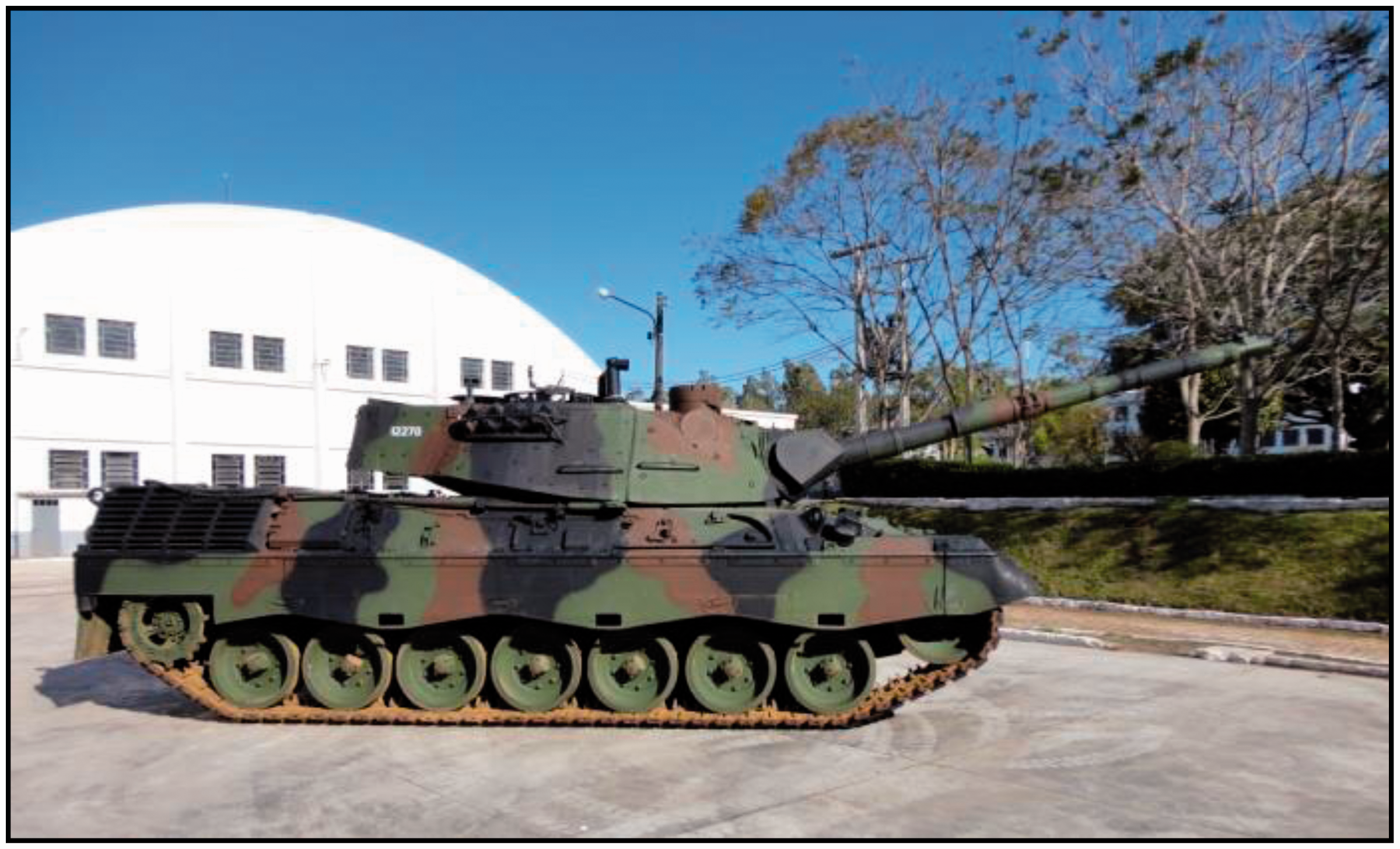
MBT Leopard 1 A5.
Acceleration data were collected at rates of 250 Hz in nine experiment trials, performed by two different drivers. The pathways were chosen to demand combat conditions, with straight and curved paths. Three different paths were tested three times each. The path which presented the highest acceleration peaks was chosen, and the three corresponding trials were used for the analysis. The Leopard 1 A5 Tank is designed to be employed in open-field all-terrain battle scenario, e.g. a cattle pasture, where the tests were performed. The 30 km/h target velocity was instructed to the driver, which is a usual velocity from the military application point of view, in a simultaneous moving and shooting task. A time window of 180 s was selected for each test. Vibration dose, RMS acceleration, and crest factor (CF) were calculated to check for shock vibration conditions, according to ISO 2631-1:1997 standard. The CF is defined as the ratio between the maximum and the RMS acceleration values. ISO 2631-1:1997 14 standard suggests that vibration analysis performed with arms is suitable for CF lower than 9. On the other hand, for higher CFs, VDV is a more appropriate indicator for shock conditions.
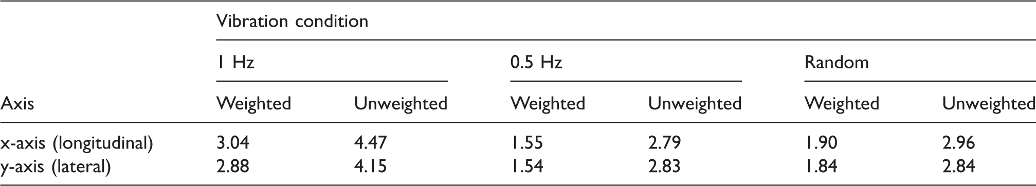
Power spectral density (PSD) was evaluated using the Welch method, with data windowed by a Hamming window (42.5 dB sidelobe attenuation), superposition of 50% and frequency resolutions between 0.05 and 0.15 Hz. Vibration data were weighted as suggested by ISO 2631-1:1997 standard. 14 The weighted data were used to design the simulator, providing a more accurate assessment of the health-related vibration characteristics, considering the simulator user safety and sensibility. However, unweighted average data for RMS acceleration, VDV, and CF are reported as well (see Table 1).
RMS acceleration, vibration dose value, and crest factor (x longitudinal, y lateral, and z vertical axis), for ISO 2631-1:1997 Standard weighted and unweighted data. Three 180 s experiments were performed.
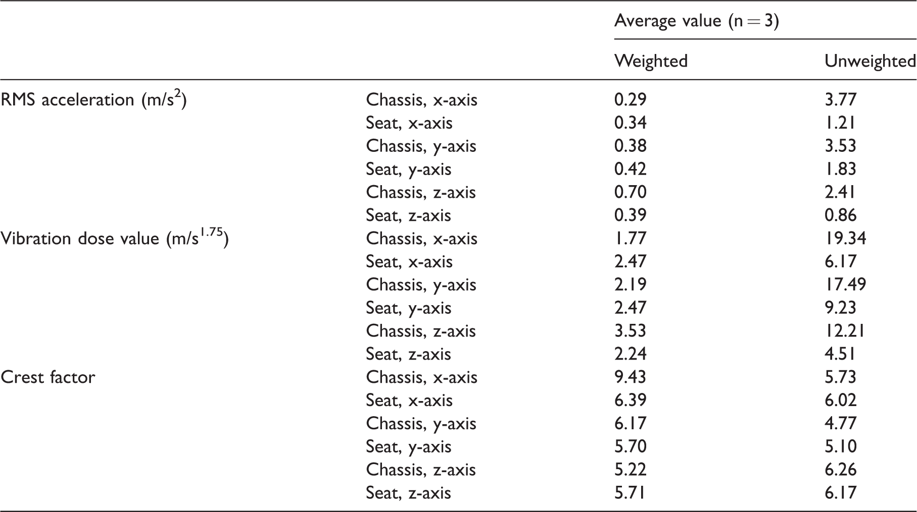
RMS: root mean square.
Turret systems identification
Black-box modeling is useful when little system physical information is available and analytical model derivation is not possible or practicable. Model parameters are adjusted for the best data fitting and may not reflect physical characteristics of the system 15 This is the case of the Leopard 1 A5 gun-turret system, which is driven by a complex set of actuators and fire control systems.
In the literature, the following family of discrete-time difference equations can summarize general black-box models

Assuming
For ARX models, equation (3) can be rewritten in discrete-time polynomial form as
17


Equations (4) and (5) represent deterministic models. However, terms expressing noise can be easily added to the structure. ARMAX (equation (6)) and nonlinear autoregressive moving average with exogenous inputs (equation (7)) models consider noise as a moving average process


Equations (6) and (7) can be rewritten as
15


In this research, to identify the azimuth system of the turret, the same IMU used for the vibration data measurements was placed at the gunner’s handle primary axis. A second, identical IMU was installed at the center of rotation of the turret. For identifying the elevation system, the IMU was placed at the gunner’s handle secondary axis (Figure 2) and the other one at the breech of the cannon (Figure 3). Simultaneous data were collected from both IMU while step inputs were provided to the handle by two operators. The sample rate for these experiments was 160 Hz. Two 300 s and five 40 s experiments were conducted for the identification of the azimuth and elevation systems, respectively.
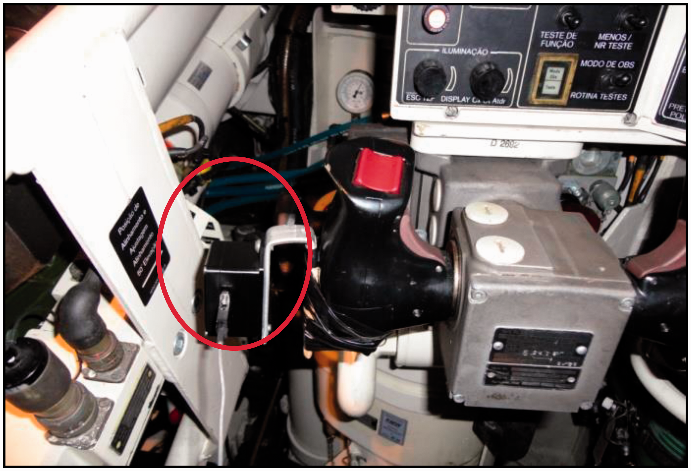
Inertial measurement unit placed at the gunner’s handle secondary axis.
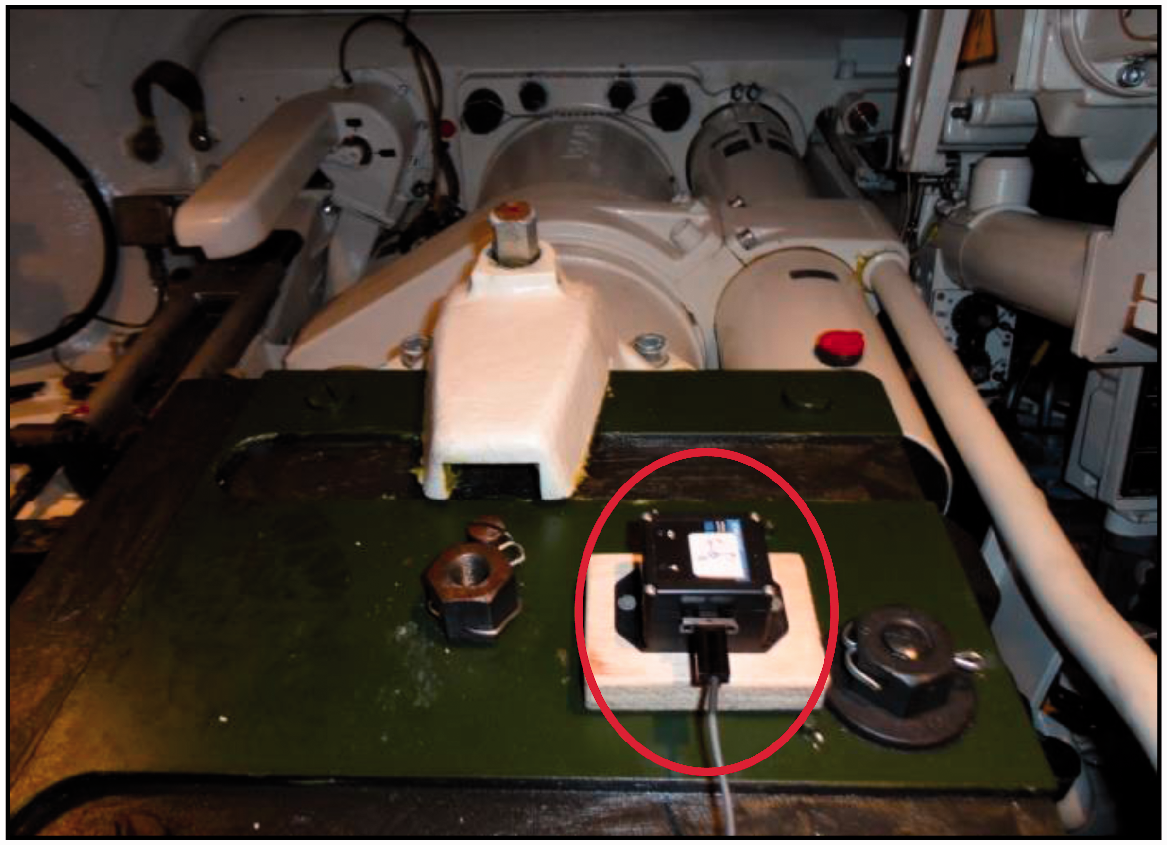
Inertial measurement unit placed at the breech of the cannon.
In the azimuth system identification, the angular rate in the vertical axis of the turret was considered as the output variable. As input, the vertical angle of the handle was used. Unfortunately, the Euler angle provided by the IMU presented a significant drift. The attitude measurement is performed by the IMU combining data from several sensors, one of them being the magnetometer, which was strongly influenced by the metallic mass of the tank. Therefore, the vertical angle of the handle was estimated from the IMU’s lateral acceleration (y-axis). For the elevation system identification, the angular rate in the local lateral axis (y-axis) of the IMU placed at the breech of the main gun was used as the output variable. Handle pitch angle, estimated from longitudinal axis acceleration, as described above, was used as the input variable. Offsets were removed, and the signal was low-pass filtered, using an 80 Hz Butterworth filter.
Step inputs for the identification process of the azimuth system consisted of random left and right turns firmly applied to the gunner’s handle. For identifying the elevation system, five cycles of up and down commands were applied to the gun barrel as step inputs.
ARX, NARX, FIR, and nonlinear finite impulse response (NFIR) structures were investigated to identify the most appropriate to reproduce main gun systems dynamics. FIR and NFIR structures can be derived as special cases of ARX and NARX structures where the regressors 
Simulator design and construction
Vibration analysis provided the requirements for designing the linkage and the pneumatic actuators of the simulator. The device consists of a platform with original gunner seat and handles attached to it. The platform moves horizontally operated by a pneumatic actuator controlled by directional and pressure regulator valves, guided by trails assembled to the platform. The response time of the valves was specified to meet frequency requirements obtained in the vibration analysis stage. An original MBT seat was used to provide the same seat transmissibility felt by a gunner. The seat is one of the most important sources of vibration transmitted to the body. Seats can be very efficient for damping vibration in the vertical direction. This characteristic reinforces the decision on studying horizontal vibration in this work. Recent studies concerning the seat transmissibility of heavy-duty vehicles show different design and control solutions for passive and active seat suspensions.18–20 Notwithstanding, the Leopard 1 A5 gunner seat consists of a simple cushion. Sophisticated seat suspensions should not be considered, in principle, as a solution for the case of the MBT, since the inner space is very restricted.
An original gunner’s handle was attached to the platform to reproduce the same posture assumed by the gunner in a MBT. Figure 4 shows the simulator assembled for longitudinal vibrations. Nonetheless, the simulator can be set up to reproduce lateral vibrations as well. The simulator’s pneumatic actuator consists of an ISO 15552, 63 mm diameter cylinder (Metalwork, São Leopoldo, Brazil), allowing 200 mm of useful displacements of the whole system (volunteer, seat, handle, and frames) with a total mass of up to 150 kg. The directional valve response time allows, theoretically, vibration frequencies up to 6 Hz. However, in this work, the highest frequency used was 1 Hz.
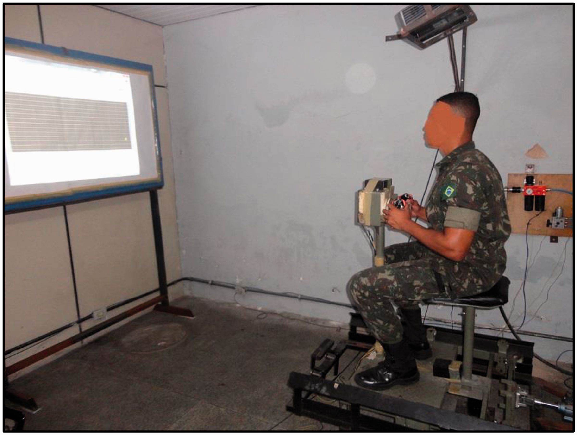
Simulator assembled for an experiment with longitudinal vibration.
In the original MBT, the vibrations occur, of course, in three dimensions simultaneously. Here, we decided to use vibrations in only one degree of freedom, for better distinguishing the eye–hand coordination under vibration in each direction separately. It should be noted that most of the current hand–eye coordination studies available in literature address mainly the vertical vibrations (e.g. Lewis and Griffin10,21 and McLeod and Griffin 11 ). Notwithstanding, by analyzing the collected vibration data, as described above and shown in the “Results” section, horizontal and VDV (longitudinal, x-axis; and lateral, y-axis) accelerations at the gunner’s seat are comparable to the vertical ones (z-axis) (Table 1). For assessing the statistical properties of the VDV distribution among the three vibration directions, the acceleration time series were merged and split into 18 parts for each direction, having the VDV evaluated in the corresponding intervals. The Shapiro–Wilk test verified that the VDVs were not normally distributed. Given that the x, y, and z directions are mechanically coupled, the VDV differences were evaluated by the repeated measures one-way Friedman test.
A LabView® virtual instrument (VI) was developed to control the directional and pressure regulator valves, using a USB National Instruments multi-IO acquisition board connected to a PC. This VI was also able to record three-degree-of-freedom acceleration data from an IMU, attached to platform chassis, as well as the gunner’s handle position data, using a pair of potentiometers. Furthermore, the VI displayed a cursor on a screen to simulate the displacement of a target, moving with the same apparent velocity of a typical MBT target. Simultaneously, a second cursor is shown on the screen and is controlled by the gunner’s handle, simulating a sight attached to the cannon. The response of this cursor was generated in real time from handle azimuth and elevation commands, processed with the turret’s black-box model obtained during the system identification stage (equations (11) and (12), “Results” section). The software also evaluates the tracking error between the two cursors, based on the Euclidean distance.
Results
The PSD analysis of the gunner’s seat acceleration (Figure 5) found peaks near 0.8 Hz (x-axis), 0.5 Hz (y-axis), and 0.8 and 1.6 Hz (z-axis) for the WBV measured at the gunner’s seat (weighted data). The evaluated RMS acceleration ranged between 0.3 and 0.5 m/s2 (weighted) and 3.5 and 3.8 m/s2 (unweighted) (Table 1). Table 1 suggests possible higher VDVs for the x- and y-axes than for the z-axis of the seat. This finding could be partly explained by the better ability of the seat to attenuate vibration in the z-axis. However, one-way Friedman test indicated that, for the seat of the gunner who took part in the experiment, the same doses among all the vibration directions were applied during the field tests (p = 0.5134). It can be observed in Table 1 that CF remained lower than 9, except for the first case experiment, in the x-axis. It demonstrates that the vehicle suspension is effective in isolating vibration and, mainly, shocks. Table 2 shows the RMS accelerations measured on the platform frame of the simulator, with different driving signals (1 and 0.5 Hz periodical, and random). It can be observed that the values are in the same order of magnitude observed in field experiments with the tank.
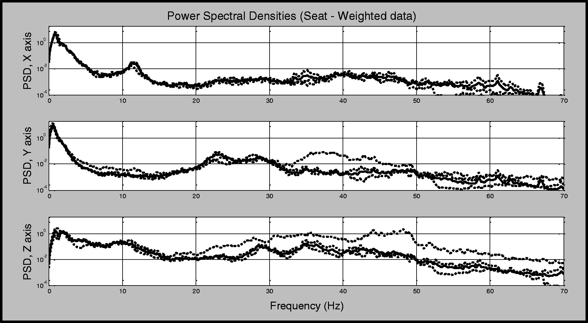
PSD analysis for the gunner’s seat accelerations (weighted data), (x longitudinal, y lateral, and z vertical axis). Dotted lines correspond to each of the three single experiments and solid lines correspond to the average values. PSD: power spectral density.
RMS acceleration values (m/s2) measured at the simulator platform frame.
RMS: root mean square.
As shown in Table 3, the best fit for the azimuth system was obtained using a second-order NARX model. Nonetheless, for real-time applications, this is a computationally expensive model, requiring the manipulation of 20 parameters, for using nonlinear regressors up to the fifth power. The trade-off between model complexity and data fitting is the first-order, fifth-degree NFIR model (equation (11)) (corresponding to NFIR_1_YAcc in Table 2). For the elevation system, following the same criterion, the second-order FIR model expressed by equation (12) (FIR_2_XAcc) was the best option


Residual analysis.
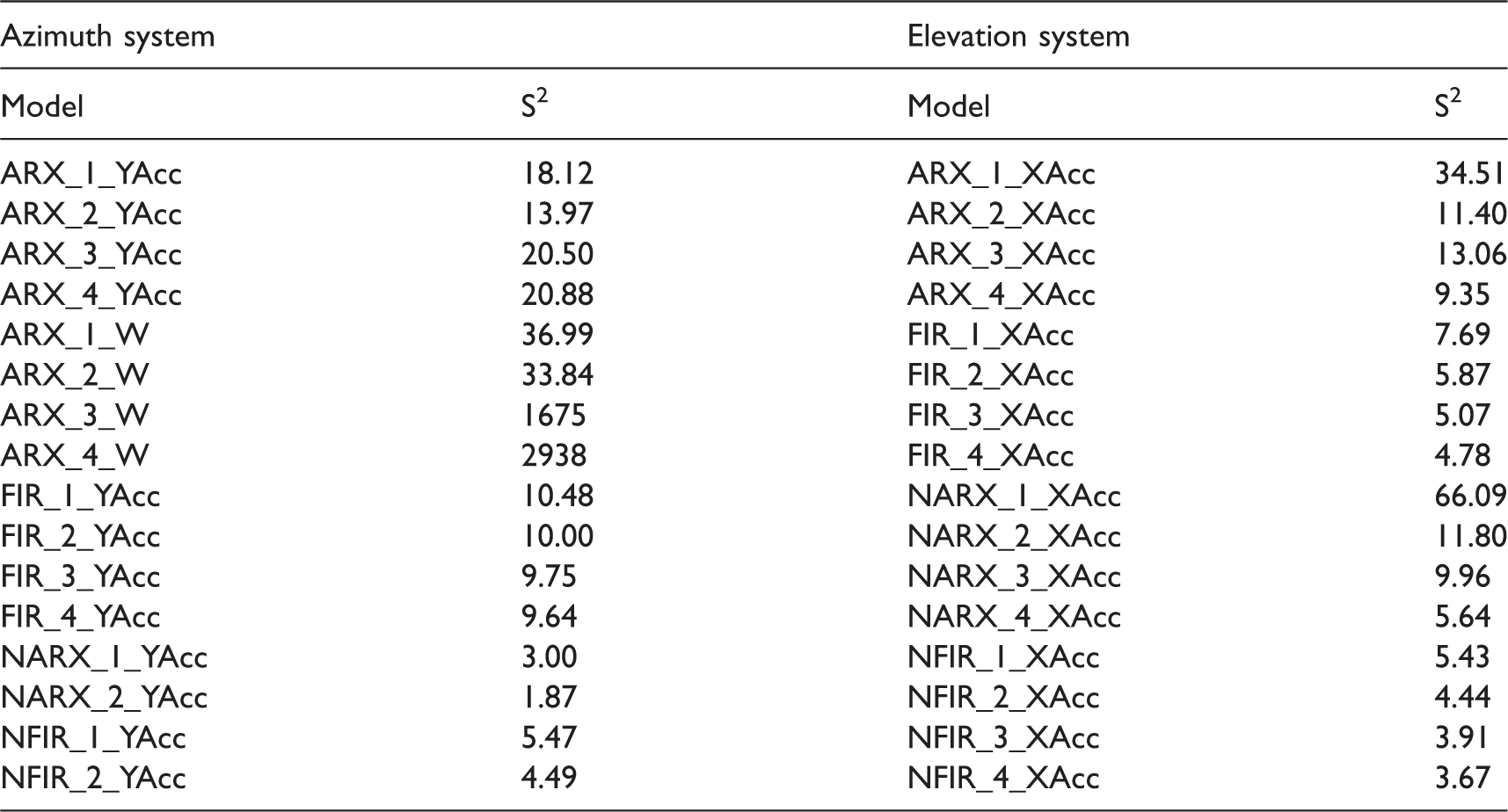
ARX: autoregressive with exogenous variables; FIR: finite impulse response; NARX: nonlinear autoregressive with exogenous inputs; NFIR: nonlinear finite impulse response.
Model type: numbers represent the order of the model; W means that angular rate was used as input variable; YAcc and XAcc indicate, respectively, that the angular displacement (input variable) was evaluated using acceleration components aligned with the lateral or longitudinal axis.
Figure 6 shows experimental data and model simulations for first- and second-order NFIR models of the azimuth system of the turret. Similarly, simulations for first- and second-order FIR models of the elevation system can be observed in Figure 7.
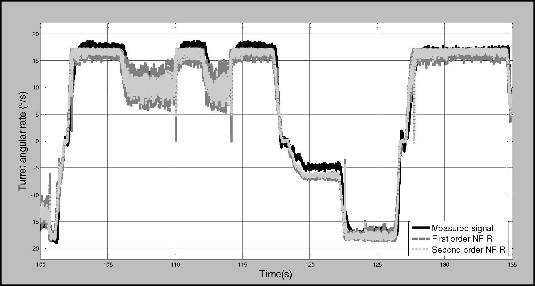
Turret azimuth system dynamics simulation response, considering first- and second-order NFIR models. FIR: nonlinear finite impulse response.
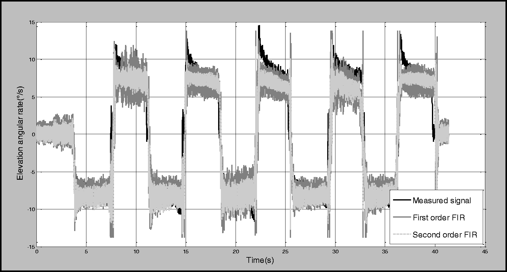
Turret elevation system dynamics simulation response, considering first- and second-order NFIR models. FIR: finite impulse response.
An example of the tracking error in an experimental test with longitudinal vibration (1 Hz) is shown in Figure 8. Two phases of the task can be identified: target acquisition, corresponding to the relatively high error and tracking. A measure of the whole test tracking performance can be obtained by calculating the root mean square of the error curve in the entire task time span.
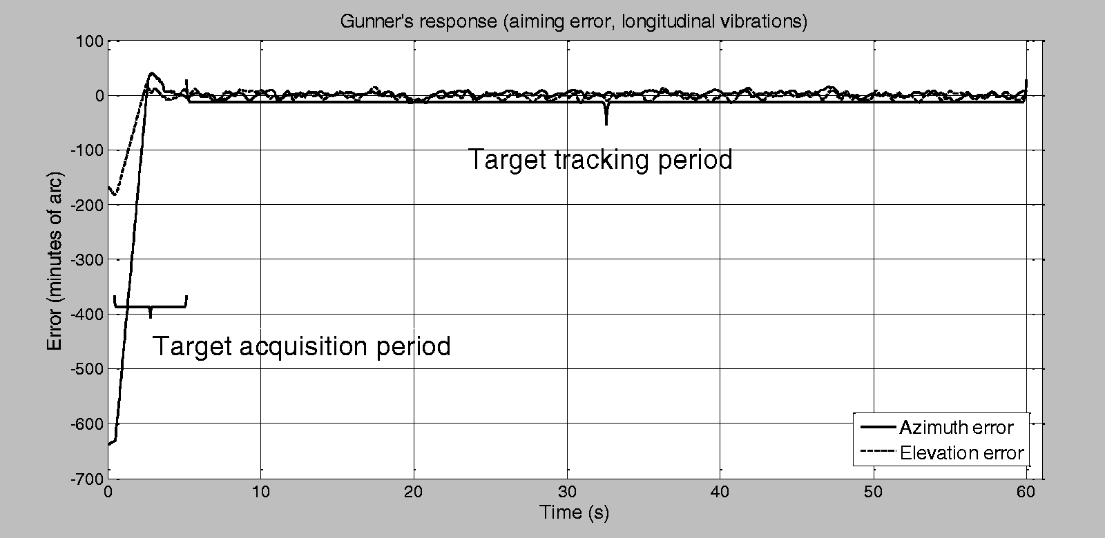
Measured tracking error between target and gunner’s handle cursor for longitudinal vibration, 1 Hz. FIR: finite impulse response.
Discussion and conclusions
This paper presented the development of a tank simulator for studying the influence of horizontal vibrations in the manual tracking of a visual target. The simulator can represent in laboratory conditions some vibration characteristics and turret dynamics response experienced by a MBT gunner. The aimed target and sight are shown on a screen in front of the volunteer. The simulator software can easily evaluate target acquisition and tracking error.
Field tests with a real MBT were performed in a rough terrain to collect 3D acceleration data, for specifying vibration frequency and magnitude. These data were used for designing the simulator. In operating the Leopard 1 A5 MBT in a rough terrain, it was observed, at the gunner’s seat, possible higher VDVs for x- and y-axes than for z-axis, contributing to the decision on studying horizontal vibrations. The PSD analysis has shown frequency peaks at 0.8 and 0.5 Hz, respectively, for x- and y-axes. These data were weighted by ISO 2631-1 Standard weighting factors for simulator design purposes, although unweighted RMS acceleration, VDV, and CF were also provided (Table 1).
The dynamic characteristics between gunner’s handle position and turret angular velocity were identified through black-box models and implemented in the simulator in real time. Several architectures of autoregressive models were tested, being the second-order NARX the one that provided the smallest residuals between the model and the measured angular velocity data. However, to provide faster but still accurate real-time simulations, first-order, fifth-degree NFIR was implemented for the azimuth of the cannon and second-order FIR for the elevation.
The constructed device can partly reproduce one-degree-of-freedom vibrations, with characteristics that resemble a MBT running in a rough terrain. Furthermore, the device allows variations of longitudinal and lateral vibration parameters. We have shown, in Figure 8, a sample tracking error result under periodic vibration. Random input signals have been tested in the simulator as well. The volunteers related that the tracking task was easier with random than with periodic inputs. It agrees with the findings reported by Lewis and Griffin 22 that, in many cases, the adverse effect of the largest amplitude of sinusoidal vibration on visual acuity is greater than the multiple frequencies of vibration. This effect may be explained by the larger number of nodal images that are generated over an area of the retina when multiple frequencies are present. 23
Due to construction constraints, the maximum allowed vibration frequency is inverse to the seat displacement amplitude. The human body is known to be particularly sensitive to the 1–4 Hz. 12 In this work, arm and hand rigid-body movements caused by trunk-induced vibrations are supposed to impair hand–eye coordination largely. The frequencies able to produce such wide amplitude displacements are necessarily low and, at this range, ISO 2631-1 Standard weighting factors enhance the acceleration amplitudes’ importance relatively to the higher frequencies. The constructed device, actuated by a double-acting pneumatic cylinder, is suitable for generating such large displacement vibrations, although with limited frequency bandwidth and trajectory shape, contrarily to an electrodynamic shaker. The ability of the simulator to reproduce RMS horizontal accelerations of the same order of magnitude of the tank in field tests was shown in Tables 1 and 2. Finer adjustments on the vibration characteristics can be performed by changing the driving signal. On the other hand, totally deterministic periodical vibrations can be easily predicted by the volunteer in a feedforward loop, tending to improve the pursuit task performance artificially.
To conclude, with limitations, the simulator can be employed in studies involving hand-to-visual control tasks accuracy evaluation and improvements, such as ergonomics, human response to vibration, filter and haptic devices design, and others.
Footnotes
Acknowledgments
The authors wish to acknowledge the support received by the Brazilian Army and, mainly, by its Regional Maintenance Park, headquartered in Santa Maria, Rio Grande do Sul, where the data acquisition took place and by the War Arsenal located in Rio de Janeiro, where the simulator was built and installed.
Declaration of conflicting interests
The author(s) declared no potential conflicts of interest with respect to the research, authorship, and/or publication of this article.
Funding
The author(s) disclosed receipt of the following financial support for the research, authorship, and/or publication of this article: The authors are gratefully acknowledged to Brazilian Government Research agencies CAPES, FAPERJ, CNPq, and FINEP for financial support.