
Abstract
In this paper, a theoretical mathematical model in conjunction with an electrical generation model is examined. Using a simulated algorithm, the optimal design of a two-mass energy harvester that finds the maximal electrical power will be assessed. Before the optimal design is performed, the influence of the electrical power with respect to design parameters such as the magnet’s height, the diameter, the stiffness of the lower springs, the stiffness of the upper springs, the revolution of the lower coil, the revolution of the upper coil, the diameter of the coil’s wire, and the electrical resistance of the loading will be analyzed. Results reveal that the design parameters play essential roles in maximizing electrical power. The two mode shapes of the two-mass energy harvester also occur at the targeted forcing frequencies. The electrical power is optimally extracted at the two primary forcing frequencies, i.e. 12 and 30 Hz. Moreover, it is obvious that the induced electrical power of the two-mass energy harvester will be superior to that of the one-mass energy harvester.
Introduction
Because portable devices are unusually popular, durable electrical power for these devices is a concern. However, there is the problem of electrical exhaust during prolonged use. So as to provide sufficient and continuous electrical power, interest in portable energy harvesters with a spring–mass system has surfaced. In 1997, Williams et al., 1 doing research with small generators, invented a wireless sensing device that was triggered by vibrational energy using a sensor that was fixed onto a bridge to detect structural status. Now, there are many energy resources including mechanical energy, thermal energy, and potential energy. Conventional work in the vibration control is to eliminate the vibrational energy using various active vibration control methods and vibration absorbers.2–5 As a view point of energy saving, it is an energy loss for the vibrational equipment system; therefore, along with these, there are numerous energy extraction methods such as the piezoelectric, electromagnetic, magnetostrictive, and electrostatic transducers.6,7 The electrical application of the above electrical generation devices that do not need continuous amounts of electricity is still sufficient even though the electrical power created from the vibration-based generator is small. However, because of progress in the semiconductor field, MEMS (Micro-Electro-Mechanical Systems) 8 along with various integrated circuit (IC) devices with low electrical power was developed. An example of the MEMS would be the application of vibration-based ICs used for the diagnosis of equipment using a vibrational signal via a remote monitoring system. 9
In order to extract more energy from environmental vibrational energy, many energy harvesters have been proposed. Also, various piezoelectric energy harvesters with low electrical power have been created. However, they are fragile and therefore risky when used at lower frequencies to extract energy of higher vibrational amplitude. So, to extract energy from a lower frequency vibrational source, an electromagnetic energy harvester was presented. In previous studies, a portable one-mass vibration-based energy harvester used in extracting vibrational energy from equipment has been developed. Sapinski 10 developed a generator for a linear magnetorheological damper using permanent magnets and coil with foil winding. However, electrical power with one-tone resonation has been limited and is insufficient. 11 Later, Chiu et al. 12 assessed three kinds of portable one-mass pendulum-arm energy harvesters using experimental tests. But, because only a resonating vibration will be induced for a one-mass vibrating system, the energy extracted from the one-mass vibrational system was limited to vibration with one forcing frequency. Therefore, in order to extract more vibrational energy from equipment having multitone forcing vibration, the development of a multimass energy harvester used to extract the vibrational energy at the multitone resonating frequencies is essential. There are many related works found in literatures. 13
In this paper, in order to expand the electrical power of various frequencies (12 and 30 Hz), a portable vibration-based two-mass energy harvester is proposed. To maximize the extracted energy, two resonant frequencies of the two-mass vibrational system will be similarly tuned as two external vibrating frequencies emitted from the vibrational source. Eight kinds of design parameters—the magnet’s height (Hm), the diameter (Dm), the stiffness of the lower springs (k1), the stiffness of the upper springs (k2), the revolution of the lower coil (N1), the revolution of the upper coil (N2), the diameter of the coil’s wire (dw), and the electrical resistance of the loading (Rload)—used in tuning the system’s natural frequencies are adopted. The optimization of a two-mass electromagnetic energy harvester is performed by using the simulated annealing (SA) method. Consequently, a comparison of the outputted electrical power between the one-mass energy harvester and the two-mass energy harvester will also be assessed and discussed.
Mathematical models
Motion of the two-mass vibration system
The two-dimensional vibration-based electromagnetic energy harvester is depicted in Figures 1 and 2. In case of a base excitation is inspired simultaneously by


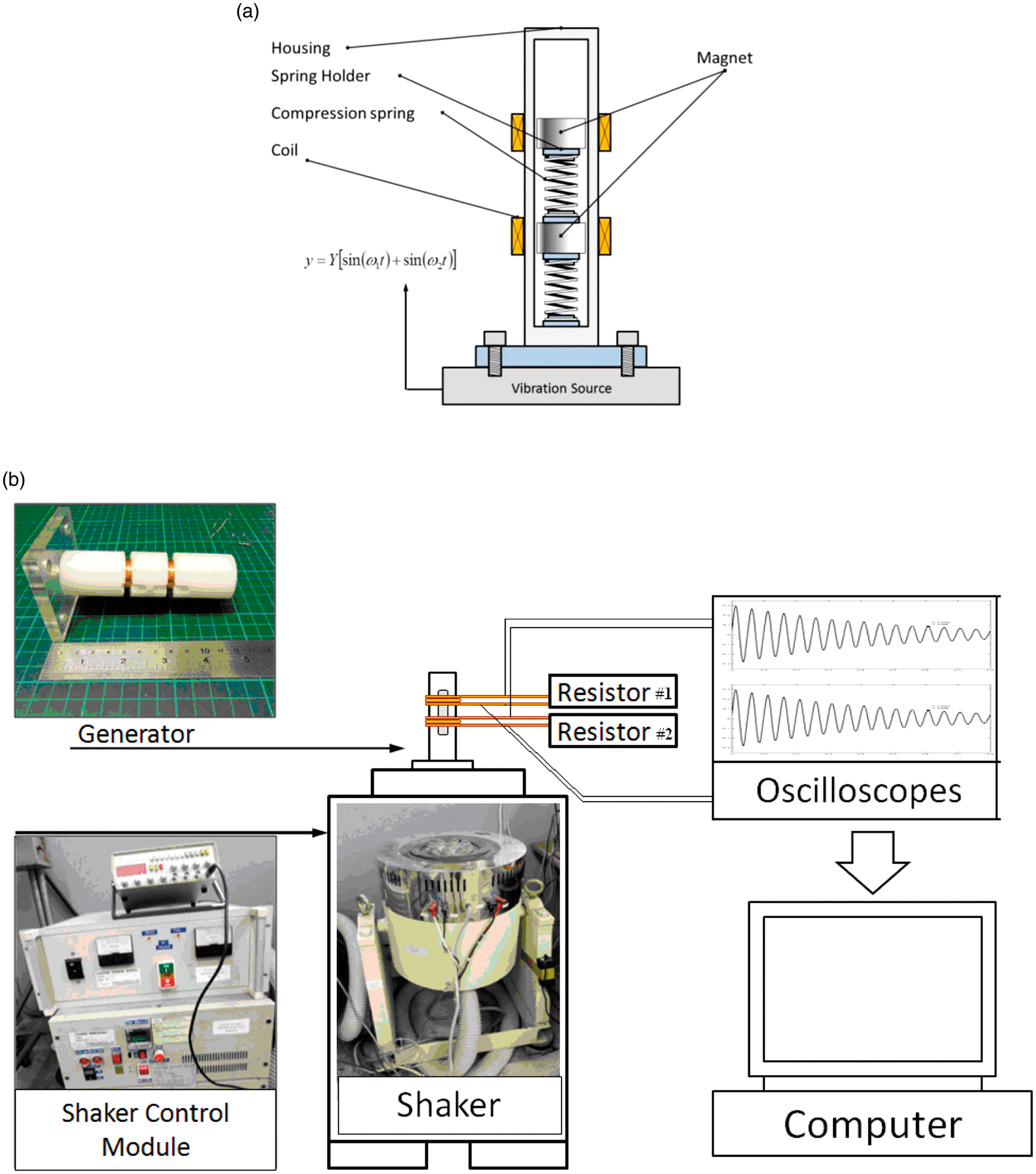
Two-dimensional base excitation with two supporting springs and two coils. (a) A mechanism of two-mass energy harvester and (b) experimental equipment for a vibration-based electromagnetic energy harvester.
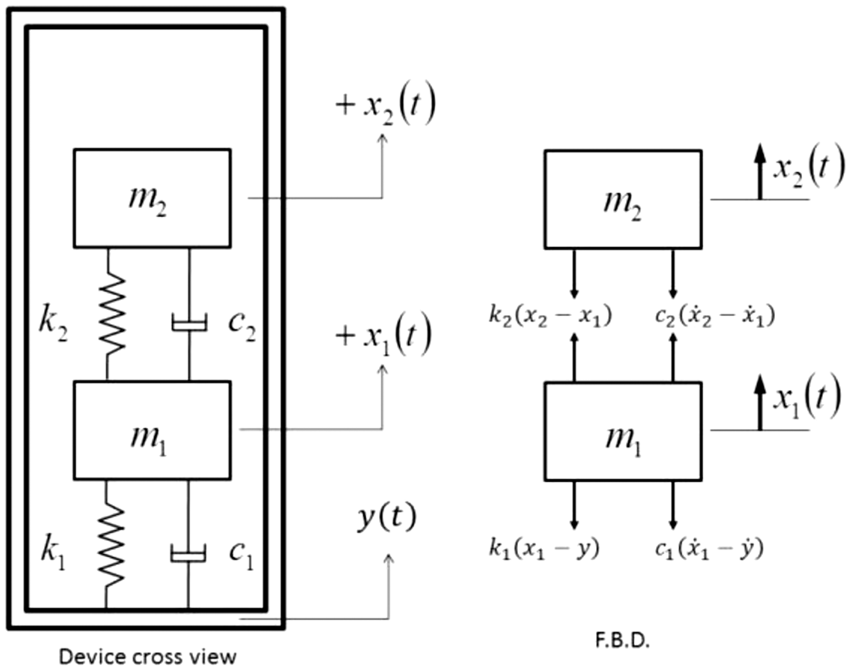
Kinetic diagram for a two-mass base-excitation energy harvester.
The motion equation for a two-mass harvester using differential operation is

Plugging equation (1) into equation (2) and performing Laplace transform yields
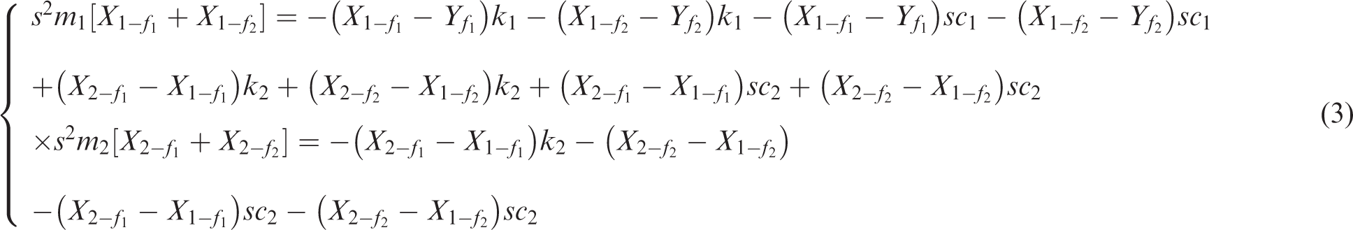
The matrix form of equation (3) is

Using the Cramer’s rule in solving
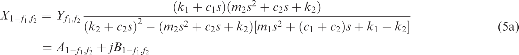
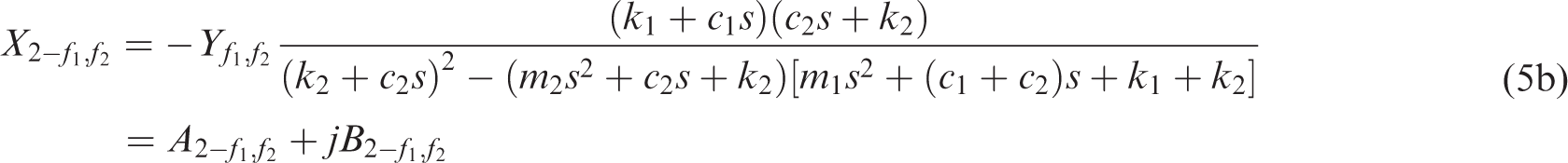
The resulting solution of


Similarly, the resulting solution of


The relative displacements of the lower magnet


In case of an excitation


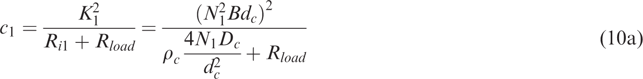
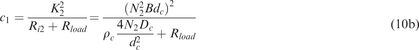
To simplify the simulation, the diameter and resistance of the coil’s wires around the upper magnet and the lower magnet are similarly designed. Therefore, for a single-layer coil, the relative damping coefficients (c1 and c2) are expressed as

For n-layer coil, the related damping coefficient yields


The magnetic flux for a permanent magnet
For a cylindrical permanent magnet, it is assumed that the inner magnetization is uniform. The coupled currents method is then applied for calculating the magnetic field of the permanent magnet.
14
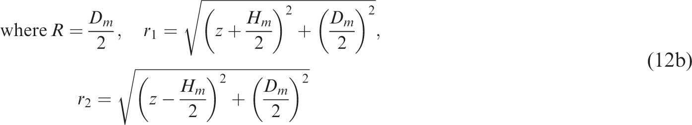
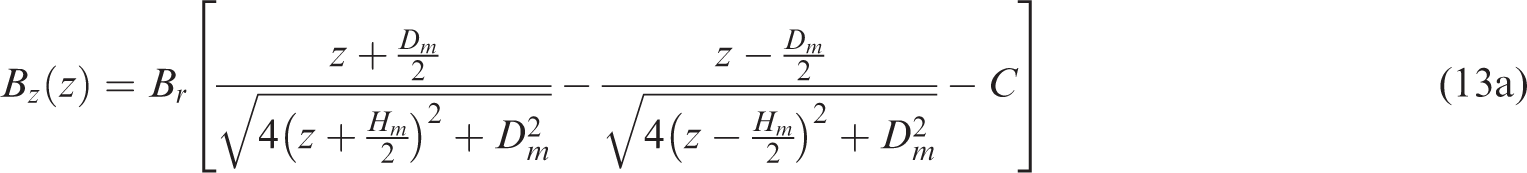
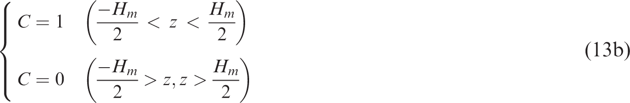
The effective current distribution is the same as an ideal solenoid. Since the magnetic field is along the z-axis only, integration of the magnetic field along the z-axis is obtained and shown in equation (12a) using the Biot–Savart law. The distribution flux density through the center of cylindrical axis is expressed in equation (13a)
15

The electromagnetic energy output
According to Wang’s analysis
16
and experimental work, a best allocation for the coil can be obtained. Results reveal that the magnetic voltage will increase if the layer of the coil increases. In order to simplify the analysis, only a one-layer solenoid/winding coil is considered. In addition, the magnet will be allocated at the center of the coil. According to Faraday’s law, the individual induced voltage with respect to each circular coil yields

For a single-layer coil, the cross area can be expressed as

For an n-layer coil, the related cross area of each layer yields

In the case of a single-layer coil, the relative displacement

Subsequently, the induced voltage of each turn is
Moreover, the total induced voltage yields
Likewise, in the case of an n-layer coil, M is the number of coil layers and N is the number of revolutions of each coil layer. The total induced voltage yields
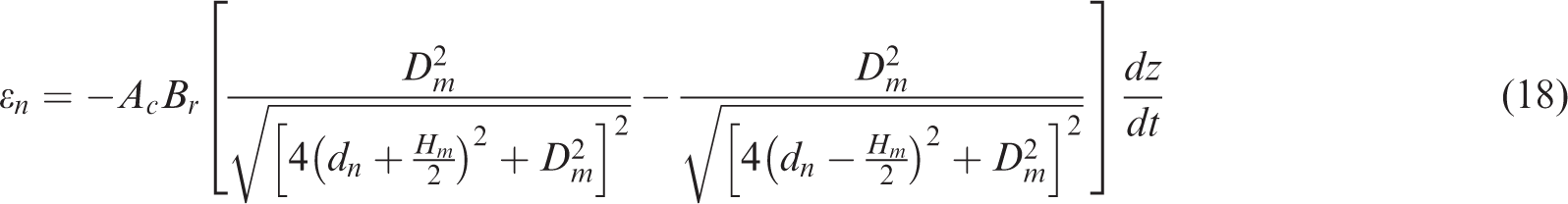
According to Faraday’s law, the individual induced voltage with respect to each circular coil yields

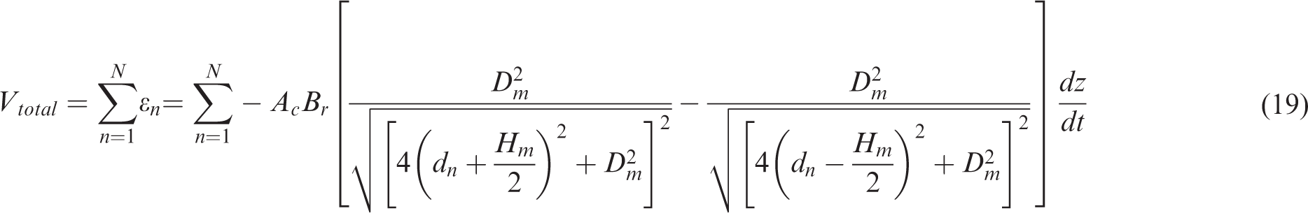
Consequently, the total voltage induced by a moving magnet will be obtained by summing up all the coil’s induced electrical voltages

Objective function
The induced system’s electrical voltage will be maximized if the system’s two natural frequencies (

The optimal design data where the system’s two natural frequencies are very close to the two targeted frequencies (
Model check
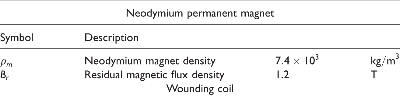
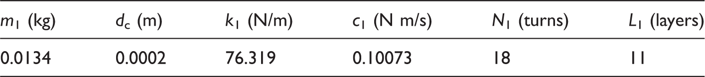
To verify the accuracy of the mathematical model and experimental data, the experimental work of a two-mass vibration-based electromagnetic energy harvester in conjunction with a vibrating source shown in Figure 1 has been established. As indicated in Figure 1, two NdFeB-made cylindrical permanent magnets serve as a vibrator. The vibrator that has a 12 mm diameter and is 16 mm in height is compressed by two springs (Stainless A313) at both ends. The selected spring is about 71 mm in ls (free length of the spring), 0.5 mm in ds (diameter of the spring’s wire), and 11.57 mm in Ds. Before the theoretical formula is calculated, some physical conditions will be preset and experimentally measured. The physical conditions are given and shown in Table 1. As indicated in Figure 1, to obtain the spring’s stiffness and damping ratio, experimental work using the logarithmic decrement method in conjunction with a piezoelectric pressure sensor is carried out. The damping coefficient can be obtained by using an experimental measurement without the coil. The damping ratio relationships are shown as below


Given data of the vibrating system and the two-mass vibration-based electromagnetic energy harvester.
The logarithmic, δ, can be calculated using the logarithmic decrement method

Using the above data in the theoretical calculation, the profile of the theoretically induced electrical voltage and the experimental voltage with respect to frequency is obtained and shown in Figure 3. The lower spring stiffness will decrease and the upper spring stiffness will increase due to the magnetic effect on the springs. In addition, because the center axis of the helical spring, the center axis of cylindrical magnet, and the center axis of the vibration source may not be set up on the same line, some vibrational energy might be dissipated in the uniaxial direction. Therefore, the practical energy detected in the experimental work will be smaller than that of the theoretical prediction. As depicted in Figure 3, the performance curve of the theoretical and experimental data is in agreement. Moreover, the maximum electromagnetic voltage is tuned to the desired frequencies of 7 and 18.4 Hz. Therefore, the mathematical model is acceptable. Consequently, the model linked by the SA numerical method is used for optimizing the unit-induced electrical voltage of a two-mass vibration-based electromagnetic energy harvester in the following section.
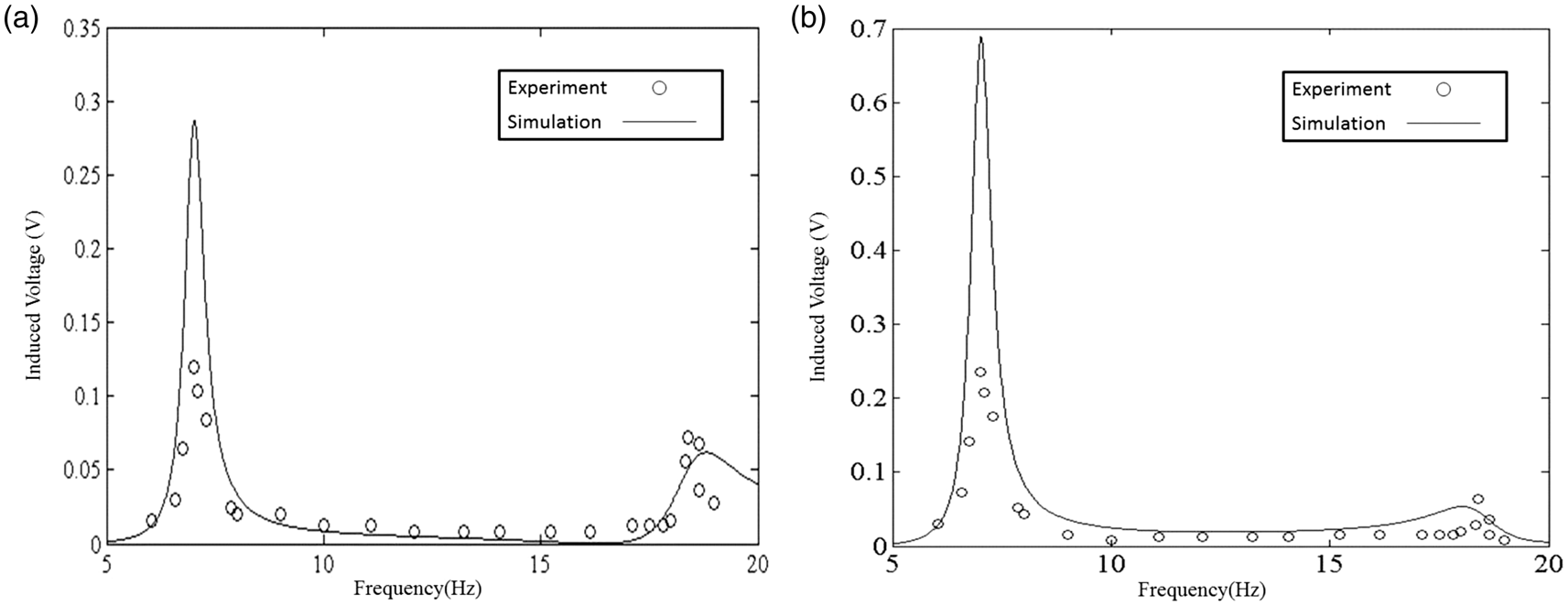
Performance of a two-mass vibration-based electromagnetic energy harvester when comparing the theoretical simulation to the experimental work. (a) The response of the lower magnet and (b) the response of the upper magnet.
Case study
There are two kinds of base vibrating sources (excited frequencies of 12 and 30 Hz) with the same displacement amplitude of 0.1 mm occurring in the equipment. To optimally extract these vibrations, a two-mass electromagnetic energy harvester is adopted. To simplify the simulation, the dimensions of two magnets and the diameter of two coal wires are similarly designed.
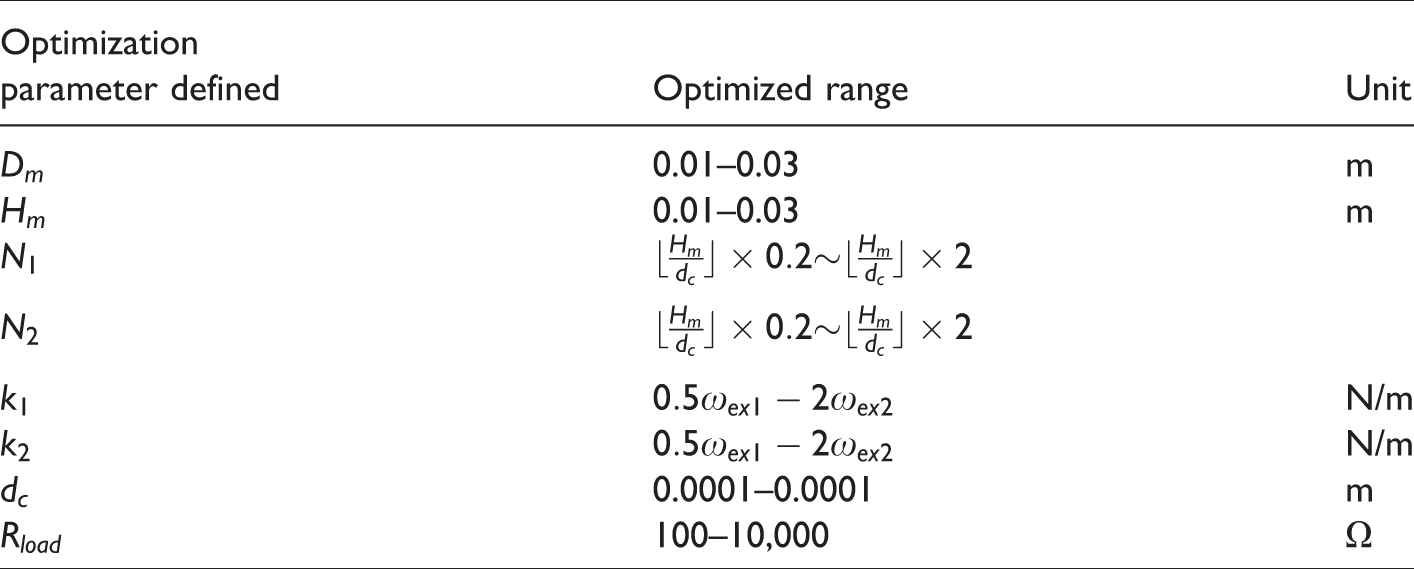
Eight kinds of design parameters—the magnet’s height (Hm), the diameter (Dm), the stiffness of the lower springs (k1), the stiffness of the upper springs (k2), the revolution of the lower coil (N1), the revolution of the upper coil (N2), the diameter of the coil’s wire (dw), and the electrical resistance of the loading (Rload)—used in tuning the system’s natural frequencies are adopted. The optimization of a two-mass electromagnetic energy harvester is performed using the SA method described in the following sections. The related ranges of the design parameters are shown in Table 2. Moreover, the data for the vibrating system and the vibration-based electromagnetic energy harvester are shown in Table 3.
The ranges of the design parameters.
The related physical property of the magnet and the coil.
Optimization process
The OBJ function is linked to the SA method. The concept behind SA was first introduced by Metropolis et al. 17 and later developed by Kirkpatrick et al. 18 The optimization flow diagram using the SA method is shown in Figure 4.
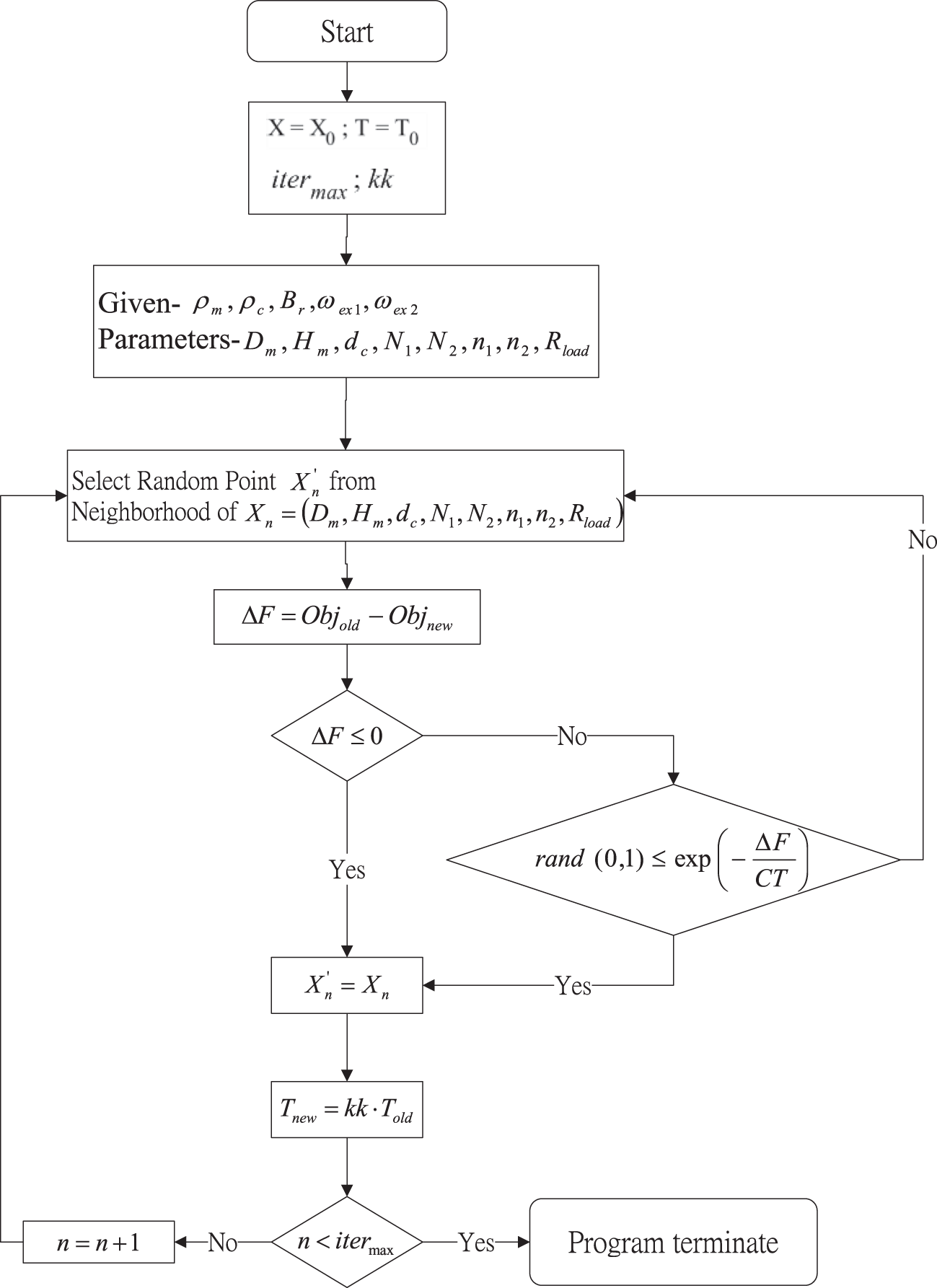
Flow diagram of a SA optimization.
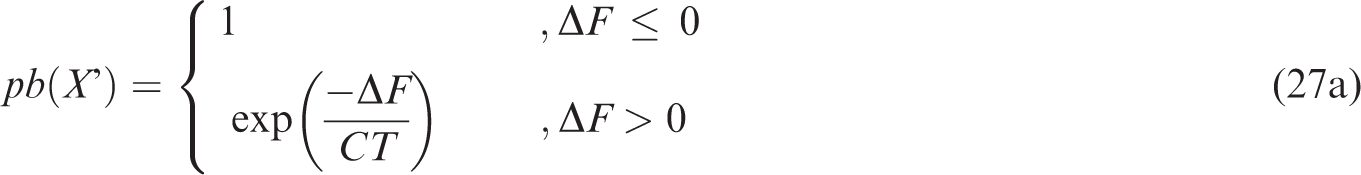
For the SA optimization process, a new random solution (X′) will be chosen from the neighborhood of the current solution (X). If the change in the objective function is negative (i.e. ΔF ≤ 0), a new solution will be acknowledged as the new current solution with the transition property pb(X′) of 1; if it is not negative (i.e. ΔF > 0), then a new transition property (pb(X′)) varying from 0 to 1 will be calculated using the Boltzmann factor (pb(X′) =exp(ΔF/CT)) as shown in equation (27)


Results and discussion
For a base-vibrating system excited by two frequencies (
Optimal OBJ for the vibration-based electromagnetic energy harvester at various kk and itermax (at targeted tones of 12 and 30 Hz with an amplitude of 0.01 m).
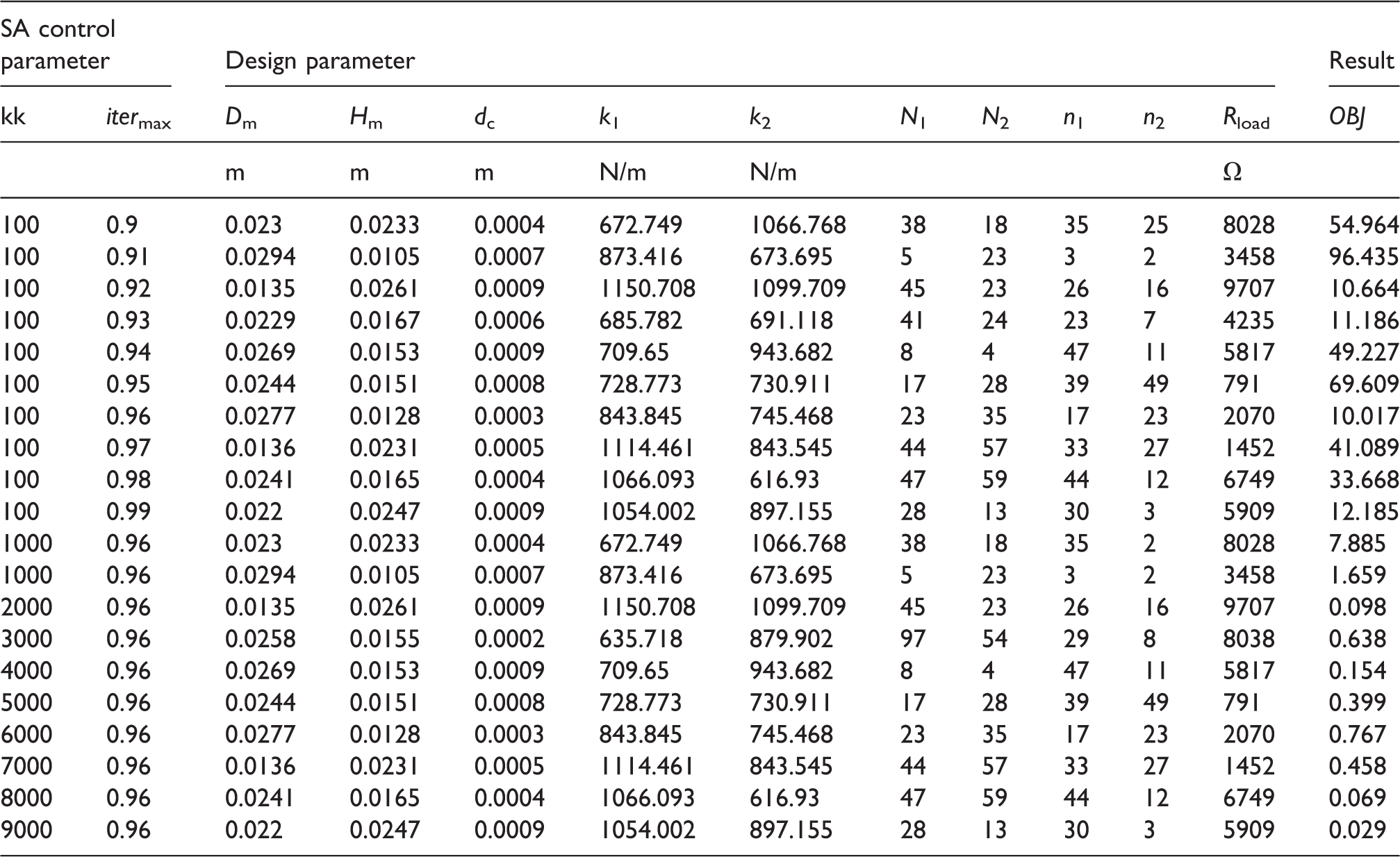
OBJ: objective function; SA: simulated annealing.
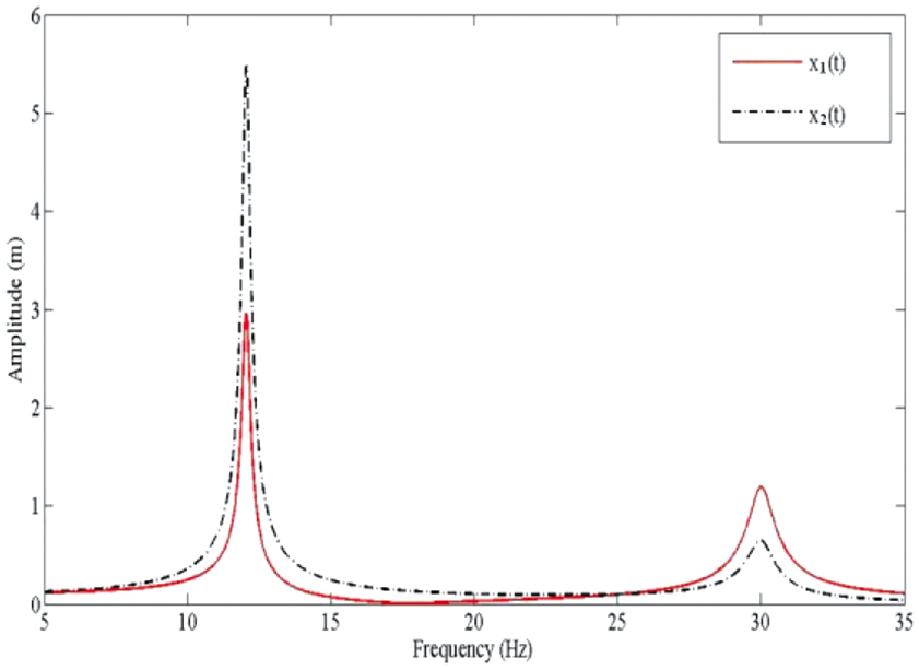
Comparison of the frequency response between the target tones (
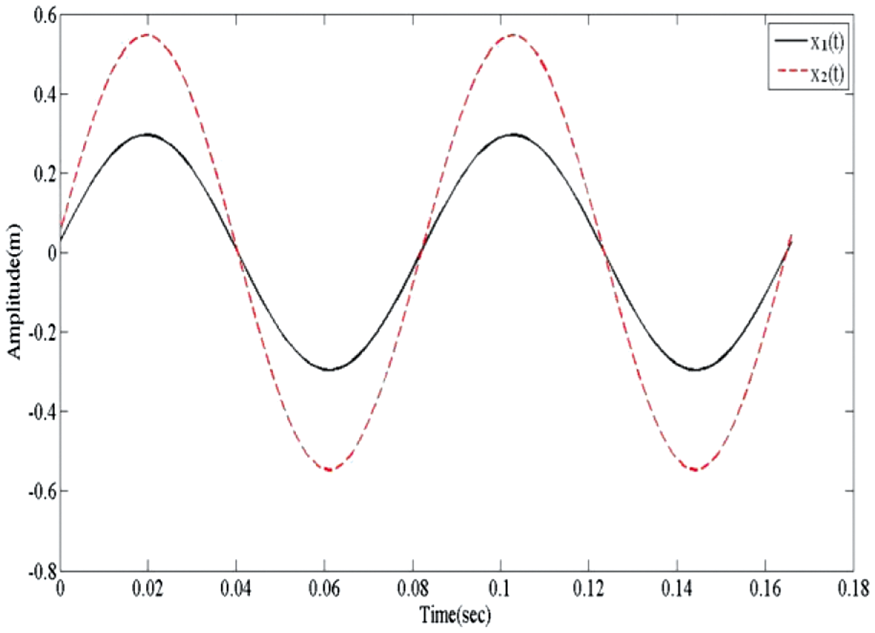
The displacements of two magnets with respect to time at the external excitation frequency of 12 Hz.
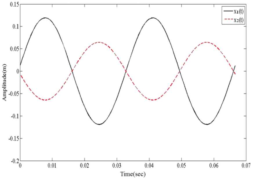
The displacements of two magnets with respect to time at the external excitation frequency of 30 Hz.
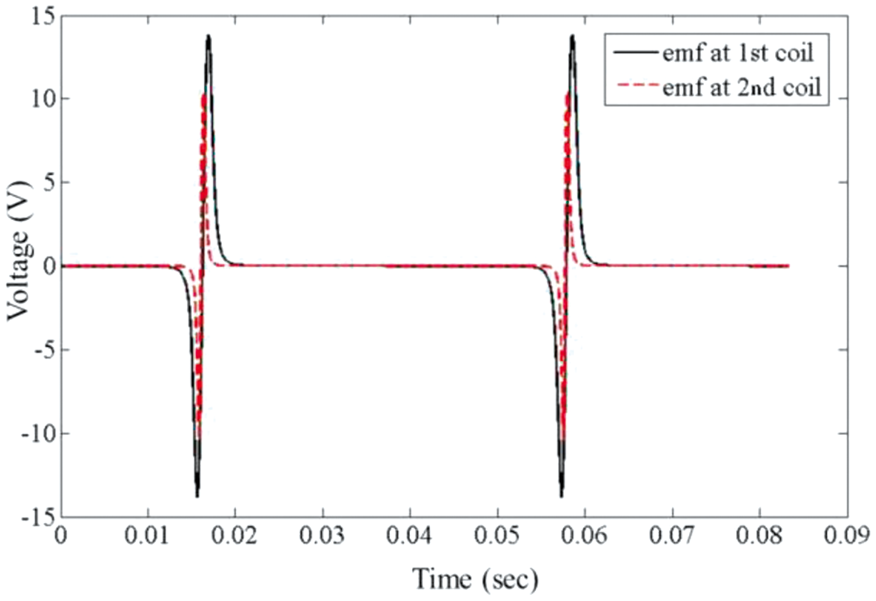
The induced voltage of two coils with respect to time at the external excitation frequency of 12 Hz during one period of time.
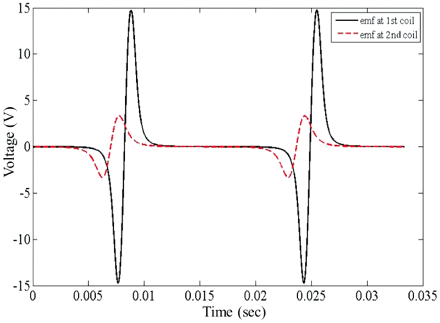
The induced voltage of two coils with respect to time at the external excitation frequency of 30 Hz during one period of time.
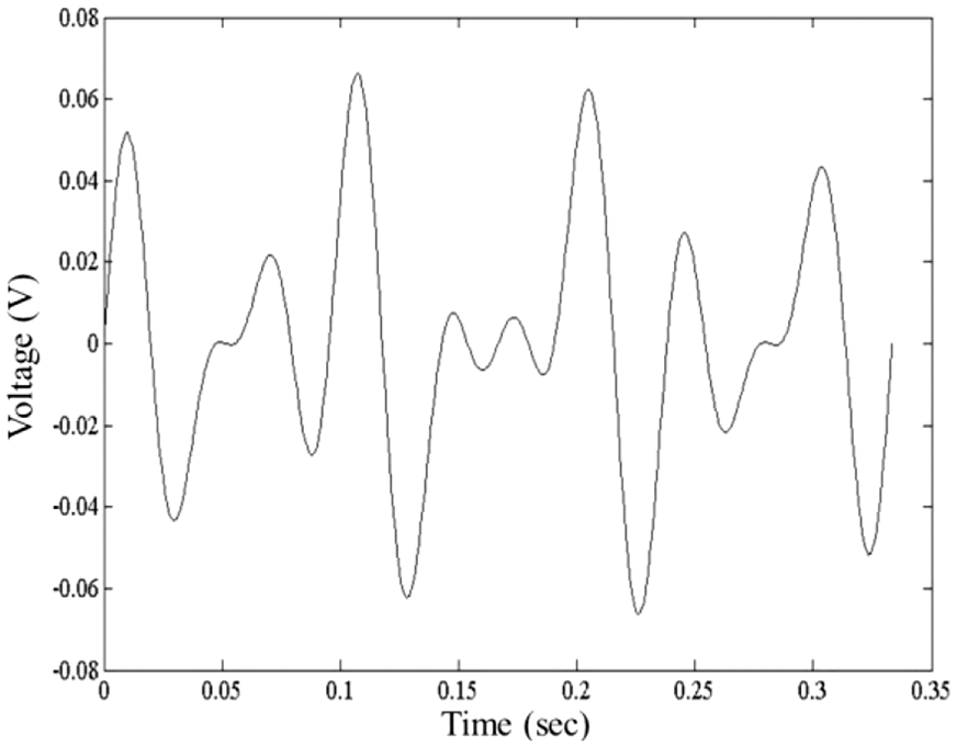
Moreover, considering two external excitation frequencies of 12 and 30 Hz simultaneously acting on the two-mass energy harvester, the electrical power of a two-magnet harvester with respect to time is shown in Figure 10.
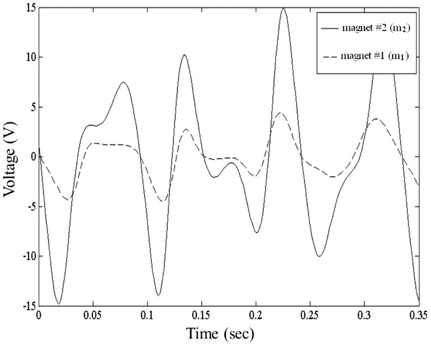
The induced voltage with respect to time of two-mass vibration system excited by two frequencies of 12 and 30 Hz.
As indicated in Table 4, the optimal design data can be obtained when the iteration number (itermax) increases and the SA’s cooling rate (kk) is 0.96. In addition, Figure 5 indicates that the system’s optimal natural frequencies (fex1 and fex2) are very close to the external forcing frequencies (
As can be seen in Figures 8 and 9, the immediate electrical power for two magnets varies periodically when two kinds of external base excitation forcing frequencies (12 and 30 Hz) are added individually. Considering two external excitation frequencies of 12 and 30 Hz simultaneously acting on the two-mass energy harvester, the electrical power of two magnets with respect to time is shown in Figure 10.
To appreciate the electrical efficiency of one-mass and two-mass harvesters in extracting the vibrational energy from a piece of vibrating equipment with two excitation frequencies of 12 and 30 Hz, the electrical power of a one-magnet harvester with respect to time is optimally assessed and presented in Table 5 and Figure 11. As indicated in Figures 10 and 11, it is obvious that the electrical efficiency of the two-mass harvester is superior to that of the one-mass harvester.
Optimal OBJ for the one-mass vibration-based electromagnetic energy harvester (at targeted tones of 12 and 30 Hz with an amplitude of 0.01 m).
OBJ: objective function.
The induced voltage with respect to time of one-mass vibration system excited by two frequencies of 12 and 30 Hz.
To realize the influence of parameters (Dm, Hm, k1, k2, dc, N1, N2, Rload) with respect to the induced voltage has been assessed and shown in Figure 12. As indicated in Figure 12(a) and (b), there are two peaks of voltage occurred at two specified values of Dm (the magnet’s diameter) and Hm (the magnet’s height) due to a two-mode resonating system. And, as illustrated in Figure 12(c) and (d), a peak of voltage occurred at a specified k1 and k2. Also, result in Figure 12(e) shows that the induced electrical voltage (V) will increase if dc (coil’s wire diameter) decreases. As illustrated in Figure 12(f) and (g), the peak of voltage will occur at a compromised number of coil turns (N1 and N2). It is because that the retarding force to the magnetic motion will increase when number of coil turns (N1 and N2). Therefore, to reach maximal electrical voltage, the coil turns must be compromised. Consequently, as indicated in Figure 12(h), the electrical voltage will remain the same when Rload (the electrical resistance) is beyond a specified value.
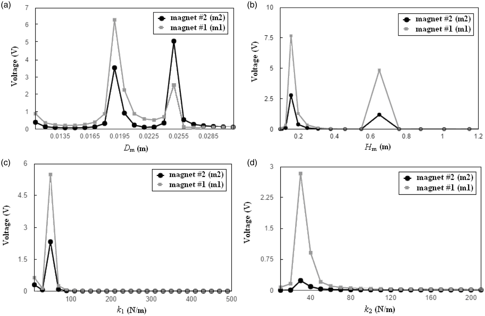
The induced voltage with respect to various design parameters (Dm, Hm, k1, k1, dc, N1, N2, Rload). (a) The induced voltage with respect to Dm while other parameters are fixed, (b) the induced voltage with respect to Hm while other parameters are fixed, (c) the induced voltage with respect to k1 while other parameters are fixed, (d) the induced voltage with respect to k2 while other parameters are fixed, (e) the induced voltage with respect to dc while other parameters are fixed, (f) the induced voltage with respect to N1 while other parameters are fixed, (g) the induced voltage with respect to N2 while other parameters are fixed, and (h) the induced voltage with respect to Rload while other parameters are fixed.
Conclusion
It has been shown that SA can be used in the optimization of a two-mass vibration-based electromagnetic energy harvester. The SA parameters of the kk (cooling rate) and the itermax (maximum iteration number) are essential during the SA optimization. The higher itermax will result in a better solution.
Concerning the geometric allocation, eight parameters (Hm: the magnet’s height; Dm: the magnet’s diameter; k1: the stiffness of the lower springs; k2: the stiffness of the upper springs; N1: the revolution of the lower coil; N2: the revolution of the upper coil; dw: the diameter of the coil’s wire; Rload: the electrical resistance of the loading) which are tightly related to the induced electrical voltage are adopted for maximization of electrical power. To increase the electrical power extracted from vibrating equipment with two primary forcing frequencies (
Footnotes
Declaration of conflicting interests
The author(s) declared no potential conflicts of interest with respect to the research, authorship, and/or publication of this article.
Funding
The author(s) disclosed receipt of the following financial support for the research, authorship, and/or publication of this article: The authors acknowledge the financial support of the National Science Council (NSC 100-2221-E-036-019, ROC).