
Abstract
In this paper, an analytical model for the flexural vibration damping of Carbon Fiber Reinforced Plastics (CFRP) cantilever beams was proposed, which is based on the Lamination Theory and Euler–Bernoulli Beam Theory. By using a finite element analysis and an analytical model, four sets of specific damping capacity with different pavement schemes were predicted, and flexural vibration test and damping analysis were carried out. Comparing the analytical model, finite element analysis, and test results, it could be found that the analytical model had relatively good accuracy in predicting the first-order natural frequency and specific damping capacity of the bending vibration of CFRP beams. The maximum error of the first-order natural frequency between the analysis result and the experimental result was 7.05%; the maximum specific damping capacity error was only 5.65%. Comparing the finite element analysis method and the experiment results, the maximum error of the first-order natural frequency was 7.8%, the error of the specific damping capacity was bigger, and the [±30°]5S specimen was as high as 18.7%. However, there was a significant error when the analytical model was used to predict the second-order natural frequency and the specific damping capacity of CFRP beam’s flexural vibration.
Keywords
Introduction
When a mechanical system and a power device are under an external interference or dynamic load, they will produce varying degrees of vibration and noise, which are harmful to the whole system. Using high damping materials or damping structure to reduce the vibration and noise has become an effective approach. 1 Fiber-reinforced plastic (FRP) has good damping properties which is 1–2 orders of magnitude higher than metals. Components made of an FRP have been used in raft frame, beams, wing plates, and blades and obtained relatively ideal vibration and noise reduction effect.2,3
Different from metal materials, an FRP has obvious orthotropy and non-linearity. 4 It is more difficult and complex to analyze its damping properties, and for this reason, it has always been the hotspot for many researchers. Adams and Maheri 5 first proposed the calculating method of an FRP’s specific damping capacity (SDC), which was the ratio between the damping loss energy and total energy in each vibration period. The damping performance of unidirectional fiber laminates was studied, and the influence rule of fiber orientation angle on SDC was obtained. Billups and Cavalli 6 summarized the damping prediction methods for 2-D FRPs, based on the prediction model proposed by Adams and Bacon 7 for the calculation of axial force and bending moment of laminates, and the damping coefficient model of free bending deformation proposed by Ni and Adams. 8 Prediction for the damping of laminates under 2-D stress was conducted, and the result was in line with the experimental result. Tsai and Chang 9 proposed a 2-D analytical model of the bending damping response of the laminated structure, and the experimental tests and finite element analysis were carried out upon the laminates with [0/−60/60]s and [0/90/45/−45]s to verify the 2-D analytical model. Based on the numerical solution of FEA, Vescovini and Bisagni 10 calculated the damping of an aircraft stiffened plate to guide the structural design of the FRP. Yang et al. 11 studied the dynamic performance of the laminated cylindrical shell based on the Rayleigh-Ritz Damping Model and the finite element method. They tested and analyzed the structural damping with excitation vibration method to obtain the contribution rate of various structural materials on overall energy damping loss. The result showed that the loss factor of structural damping not only depended on the laminate parameters of the FRP but also on the vibration mode. Rébillat and Boutillon 12 also experimented on the damping performance of the FRP with sandwich structure and established a correlation model. Bensahal et al. 13 studied the composite structure damping performance of orthogonal layer based on complex modulus and finite element method, which indicated that the structural damping parameters were related to the loading frequency. The stiffness loss of the FRP structure under different loading frequencies was also studied.
However, the accessible studies about the analytical model of the damping characteristics of the FRP all include the in-plane stress and out-of-plane stress. In this case, the analytical model is relatively complex and is not suitable for dealing with the damping with simple structures. The numerical model needs to obtain the stress and strain value of each unit in all axial directions in order to predict the damping of the FRP. By calculating the average strain energy of each unit, the overall strain energy can be obtained. In this method, the strain energy data are sensitive to mesh generation, and the process is complex.
Therefore, this paper proposes a damping loss factor matrix model of composite materials in the ply level. On the condition of ignoring stress and strain which has little influence on the bending deformation of the FRP, combining analytical methods, a fast, convenient, and accurate calculation method for the flexural damping response of composite laminates was built. It provided theoretical basis for the prediction of flexural vibration damping characteristics when an FRP laminate is used for raft frame, beams, wind plates, and blades.
Analytical solution of flexural damping response
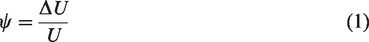
In order to describe the damping response of an FRP’s flexural vibration, a 2-D analytical model was proposed based on the energy dissipation theory and lamination theory. According to the energy dissipation concept,
14
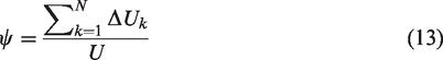
the SDC can be defined as the dissipation ratio of the strain energy for each vibration period.
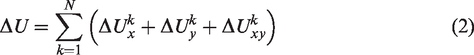
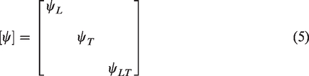
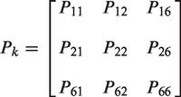
Then the offset axis SDC matrix of single-layer-reinforced plastic is

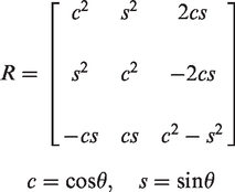
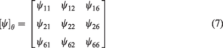
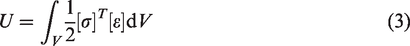
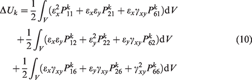
Therefore, the strain energy dissipation in the off-axis state can be expressed as
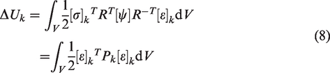

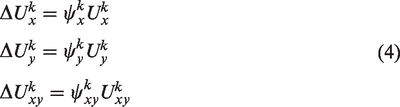
In such situation, the strain energy dissipation equation (8) can be expanded as
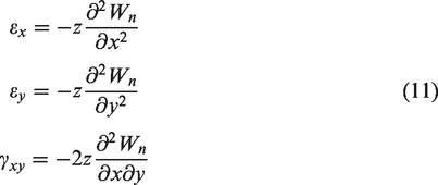
Based on the fundamental assumption of laminated structure, the plane stress in each direction during bending deformation can be obtained by the vibration displacement equation
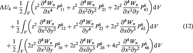
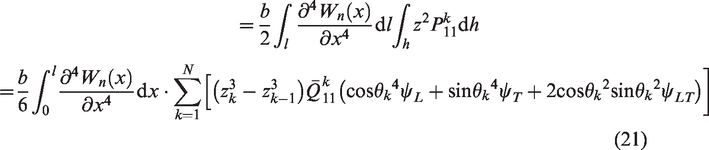
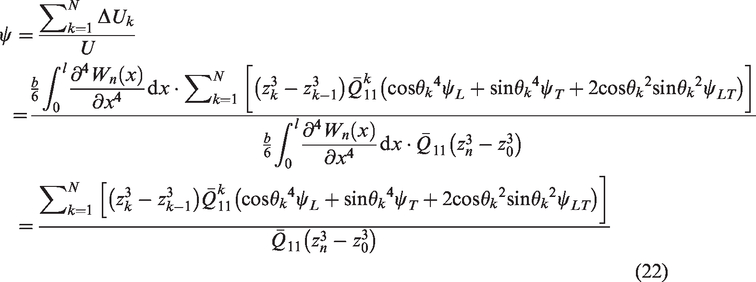
Combining the strain energy loss of each layer and the strain energy of whole structure, the SDC of the FRP in flexural vibration is
Free vibration damping of the cantilever beam
When the FRP plate is under longitudinal bending loads, the warping and transverse strains are negligibly small. Therefore, Euler–Bernoulli Beam Theory
15
can be used to study the FRP plate’s flexural vibration kinematic equation. In general, to describe the FRP’s flexural vibration damping, the longitudinal vibration response of the FRP cantilever beam is studied on the condition that the free end suffers sudden bending moment incentive. In this case, the composite beam can vibrate freely in vertical plane (x-z plane) as shown in Figure 1. The deflection w can be expressed as the function of position x along the beam direction and time t.

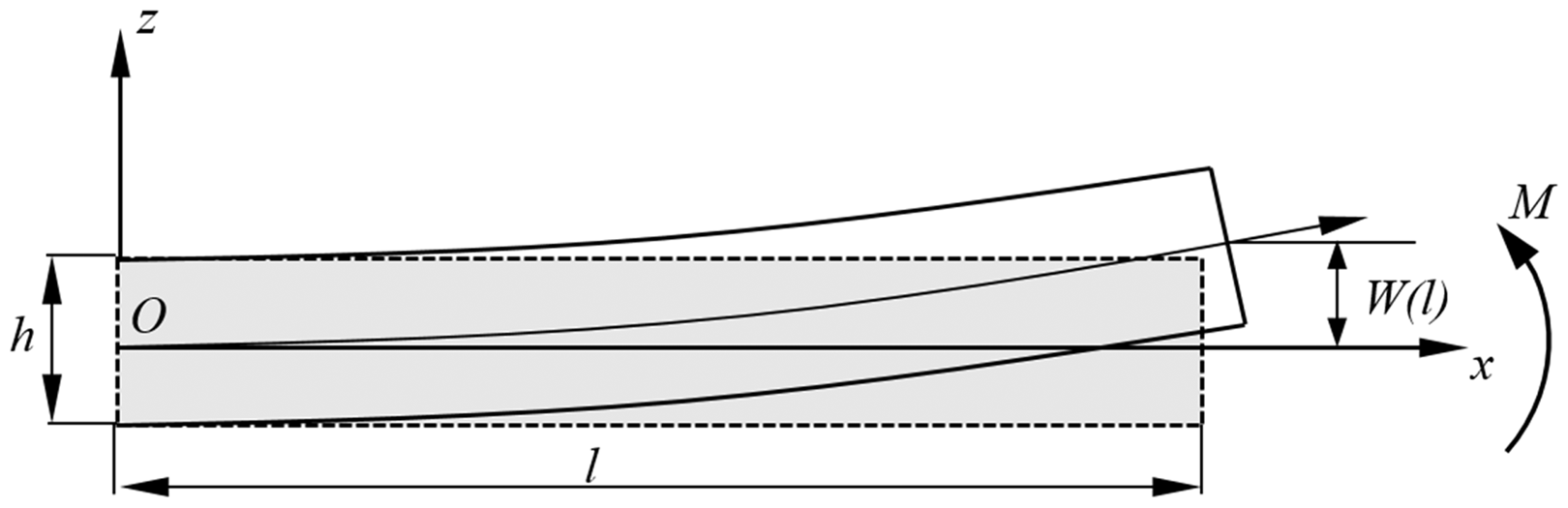
Schematic diagram of flexural vibration of the FRP cantilever beam.
The differential kinematic equation of the FRP cantilever beam is

Equation (15) can be simplified as follows
One end of the cantilever beam is completely constrained, and the other end is free, so the boundary condition of the kinematic equation is

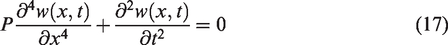
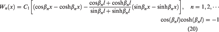
The general solution of the differential equation satisfies w(x, t)=W(x)q(t), substituting it into equation (17) can obtain the following

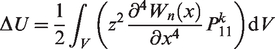
When an FRP beam makes flexural free vibration in the vertical plane (x-z plane), warping and lateral deformation are very small, that is to say εy and γxy are much smaller than εx and can be ignored. Therefore, the strain energy loss of kth layer can be derived as
Damping testing experiment
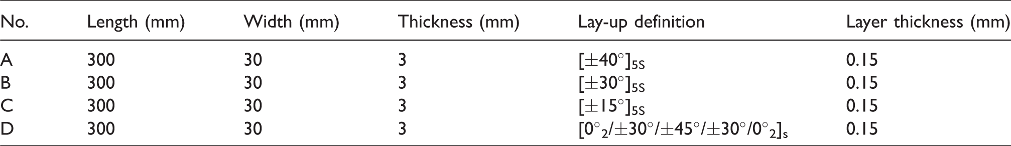
The experiment aims to verify the accuracy of the SDC analytical model of a CFRP beam’s flexural vibration derived in this paper. The specimens are made of T700/YPH-308 prepreg with molding process. The length is 300 mm and width is 30 mm, but orientation angle of each specimen is different. Two specimens are manufactured for each laminate scheme. Table 1 shows the mechanical parameters and damping loss factor of T700/YPH-308. The dimensions and laminate schemes of the CFRP specimens are shown in Table 2. In vibration test, the cantilever length of all the CFRP beam specimens is 250 mm.
Material properties of CFRP T700/YPH-308.

Configuration and dimensions of specimens.
To obtain the vibration frequency response curve, the longitudinal flexural modal of the specimens with different fiber orientation angles were measured using a vibration mode test system, based on which the SDC can be calculated. The cantilever beam vibration testing system 16 is shown in Figure 2. The CFRP beam was supported by a clamping block, forming a cantilever beam structure. An impact hammer (model B&K 7561) was used to stimulate the flexural vibration of the beam. The acceleration sensor was fixed at the free end of the CFRP cantilever beam. The acceleration sensor’s model is 30358G from Dytran Instruments Inc. with sensitivity of 105.32 mV/g. The sweep range of the signal generator is from 0 to 2000 Hz. The beam was knocked by a hammer near the fixed end for 10 times. The pulse signal collected by the force sensor in the hammer was sent to a conditioning amplifier. At the same time, the acceleration sensor on the specimen picked up the vibration acceleration response signal and sent it to the conditioning amplifier. Then, the excitation signal and response signal were processed and digitized by the dynamic analyzer from ECON Company. The best five results of coherence were averaged to obtain the frequency response curves. In the case of the low damping structure, the damping ratio can be calculated from the half-power bandwidth near the modal frequency 17 using Modal Genius software.
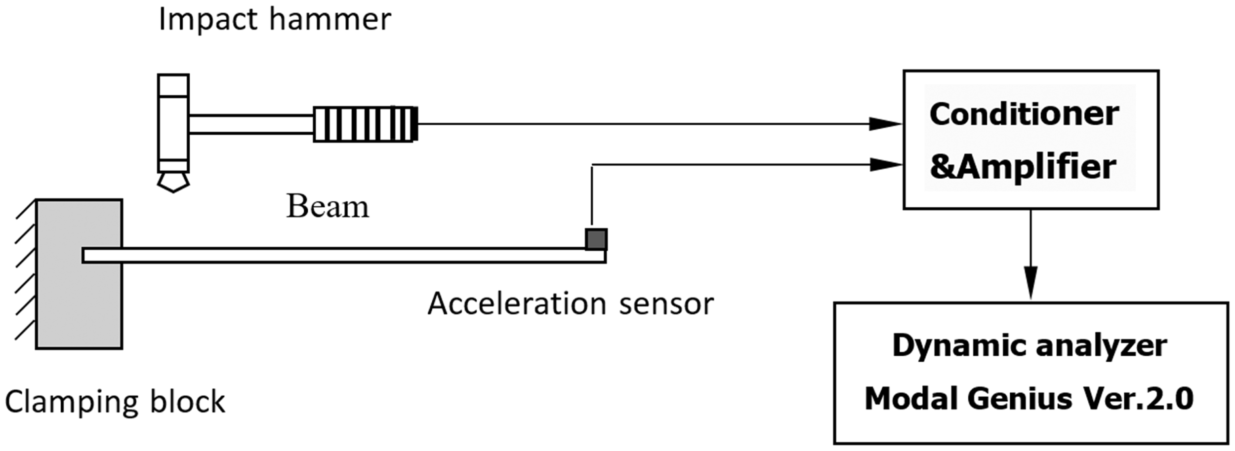
Experimental equipment.
Results and discussion
In this part, the results of the CFRP beam vibration damping test, analytical model, and finite element method are presented. The vibration damping test results are used to verify the accuracy of the derived analytical model.
Analytical results
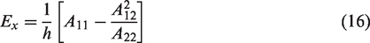
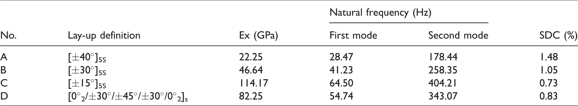
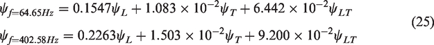
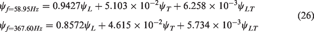
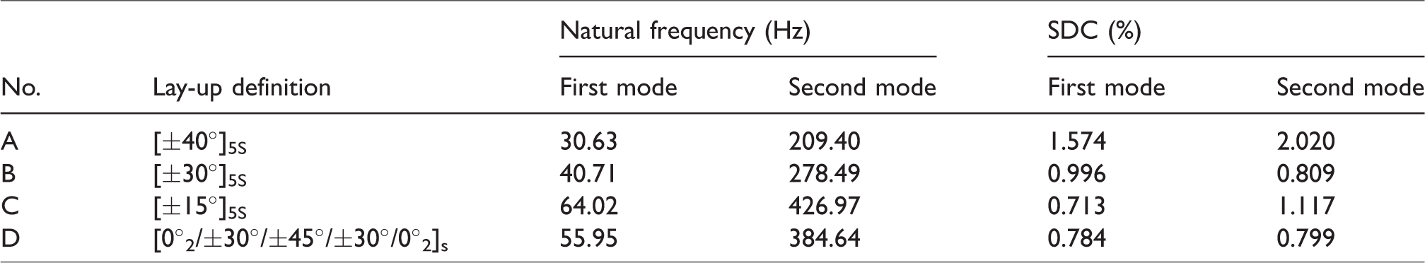
Table 3 shows the natural frequency of the first-order and second-order modals of the CFRP cantilever beams calculated by the Euler–Bernoulli Beam Theory. By bringing the frequency of each mode and the parameters of the specimen into equation (20), the CFRP beam’s vibration displacement equation was obtained. Combining the laminate scheme of specimen, kinematic equation, equations (3) and (21), the SDC of each mode is calculated. The analytical model is based on the Euler–Bernoulli Beam Theory assuming that the cross-section is rigid, without consideration of warping and lateral strain, the SDC of the analytical model in the first-order and second-order are the same (show in Table 3).
The natural frequency of flexural modality obtained by the analytical method.
FEA results
According to the finite element method proposed in literature,9,10 modal analysis of the CFRP cantilever specimen was carried out by ABAQUS 6.12. The 3-D solid model of the CFRP cantilever was established according to the dimensions of the specimen, and then the material properties and the laying scheme were defined. The 8-node shell element C3D8R was used for meshing. One end face of the CFRP beam was fixed completely and the linear perturbation analysis was carried out, and then the first-order and second-order modes of the CFRP cantilever beams were obtained. Figure 3 shows the first-order and second-order modal shapes of the specimen A. The in-plane strain cloud chart of the first layer of specimen A in the first-order mode is shown in Figure 4, and Figure 5 shows the second-order mode.
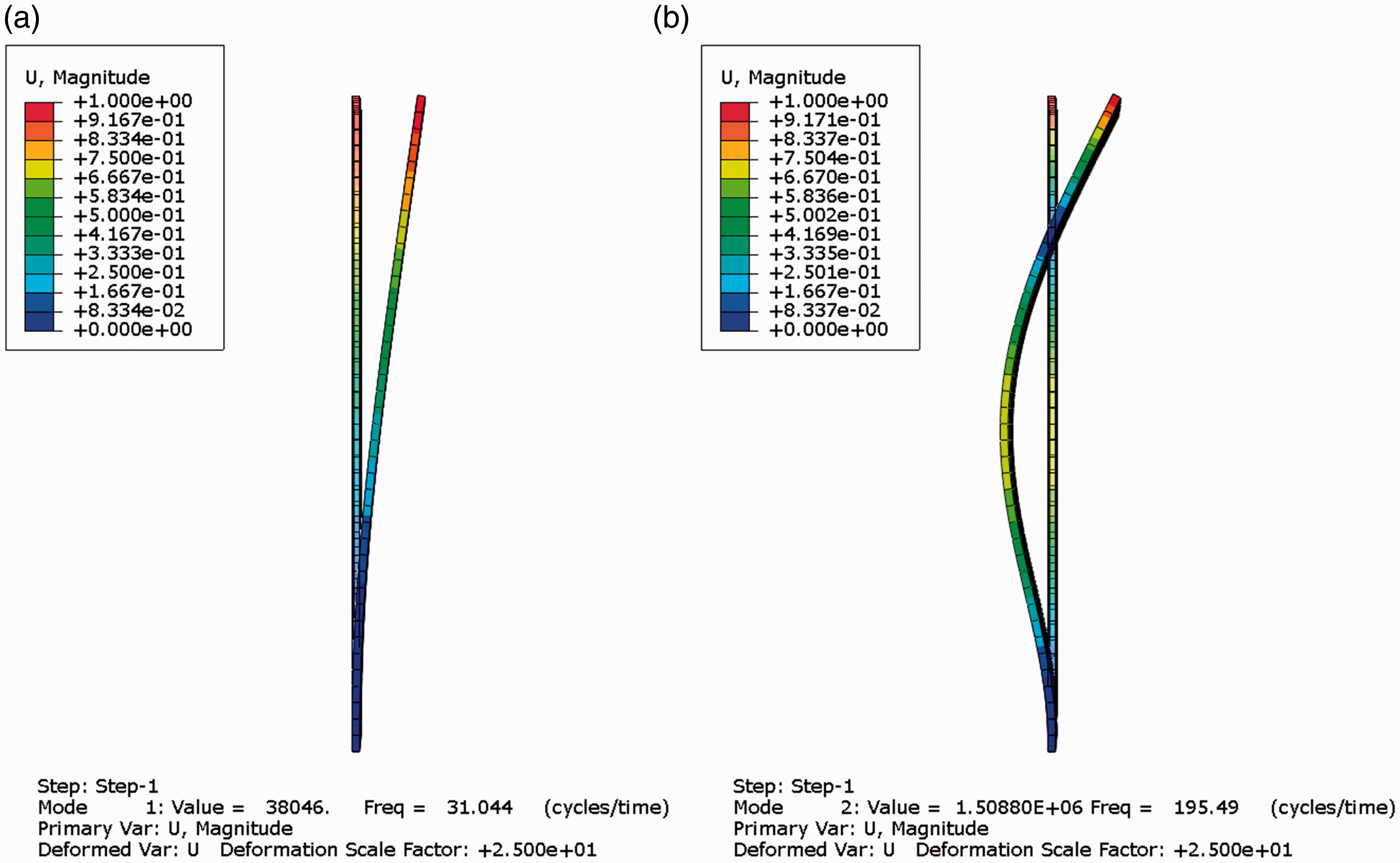
Cloud chart of modal vibration displacement of specimen A. (a) Vibration displacement at 31.44 Hz and (b) vibration displacement at 195.49 Hz.
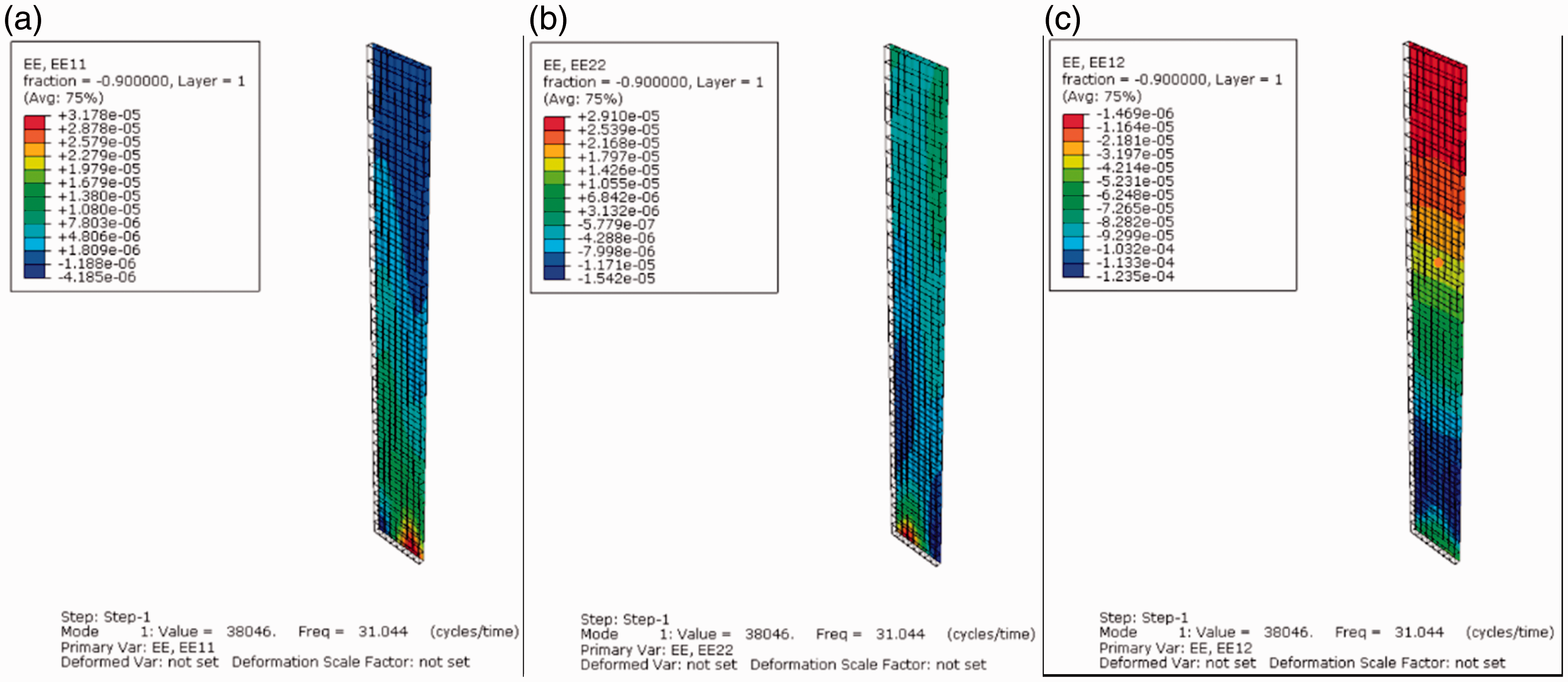
In-plane strain cloud chart of the first layer in 31.04 Hz of specimen A. (a) Strain in longitudinal direction, (b) strain in transverse direction, and (c) strain in shear direction.
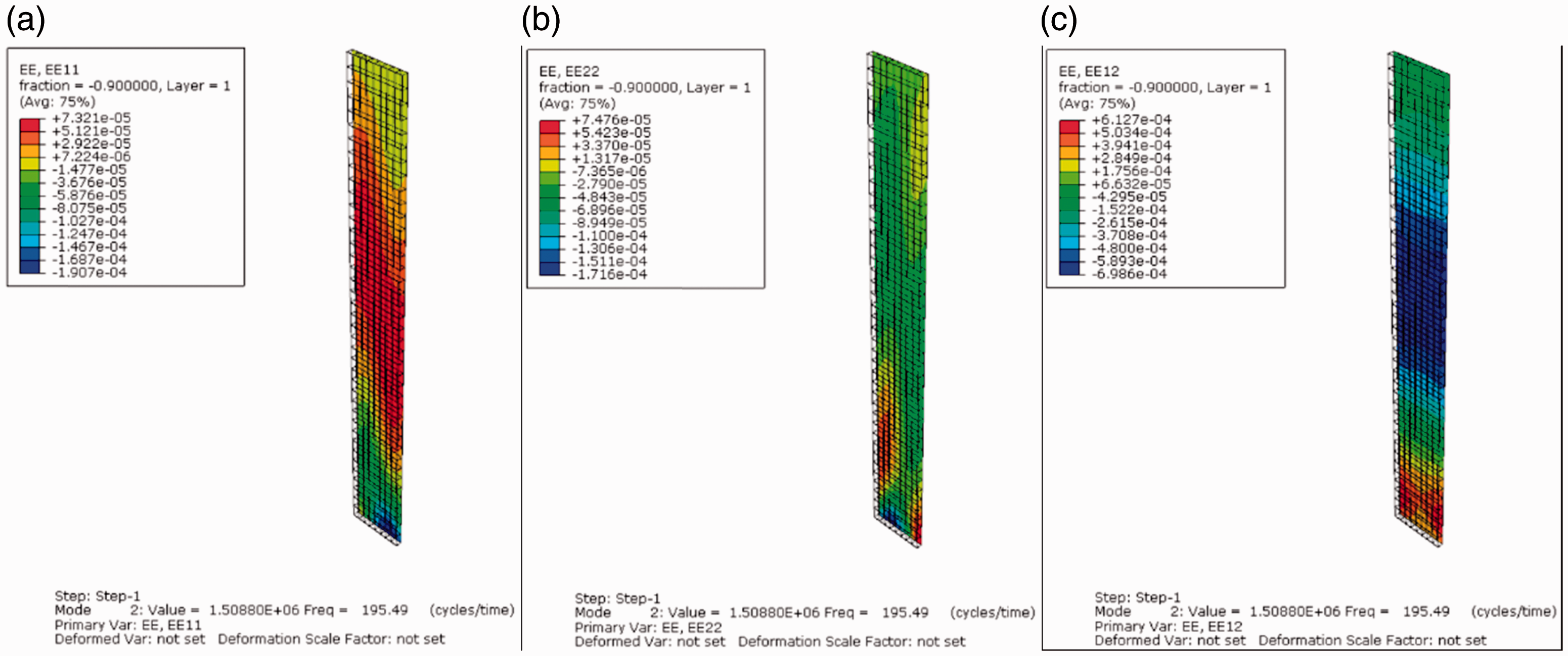
In-plane strain cloud chart of the first layer in 195.49 Hz of specimen A. (a) Strain in longitudinal direction, (b) strain in transverse direction, and (c) strain in shear direction.
Then, the in-plane strain of each element in each layer was extracted, and the strain energy and strain energy loss of the laminate were obtained. Combining the strain energy calculation method from earlier studies,9,10 the relationships between SDC and damping loss factor of T700/YPH-308 are shown as follows
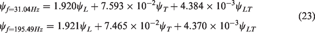
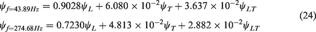
Substituting the damping loss factor of T700/YPH-308 in Table 1 into the equations (23) to (26), the SDC are presented in Table 4.
The modal frequency and SDC obtained by FEA.
Experimental results
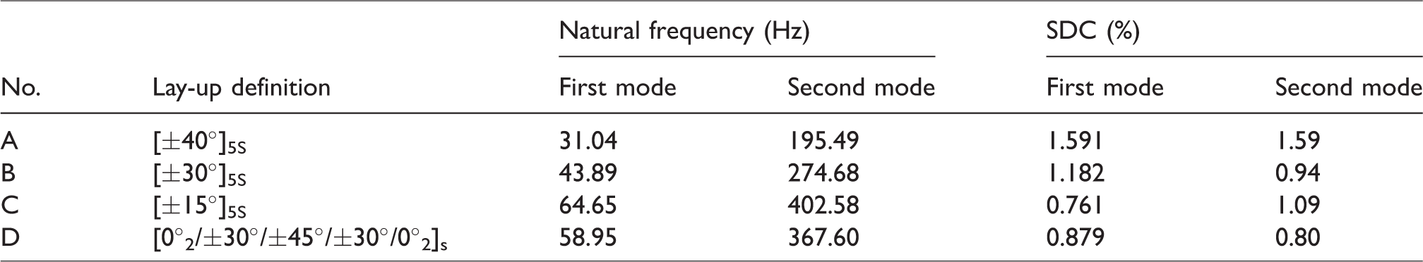
The vibration test frequency response curve of each specimen was obtained as shown in Figure 6. The frequency response curve was introduced into the Modal Genius modal analysis software, and the band cursor was adjusted. The Orthogonal polynomial for single reference method was used to analyze and solve frequency response function, and the flexural modal frequency and damping loss factor were obtained. The experimental results are shown in Table 5.
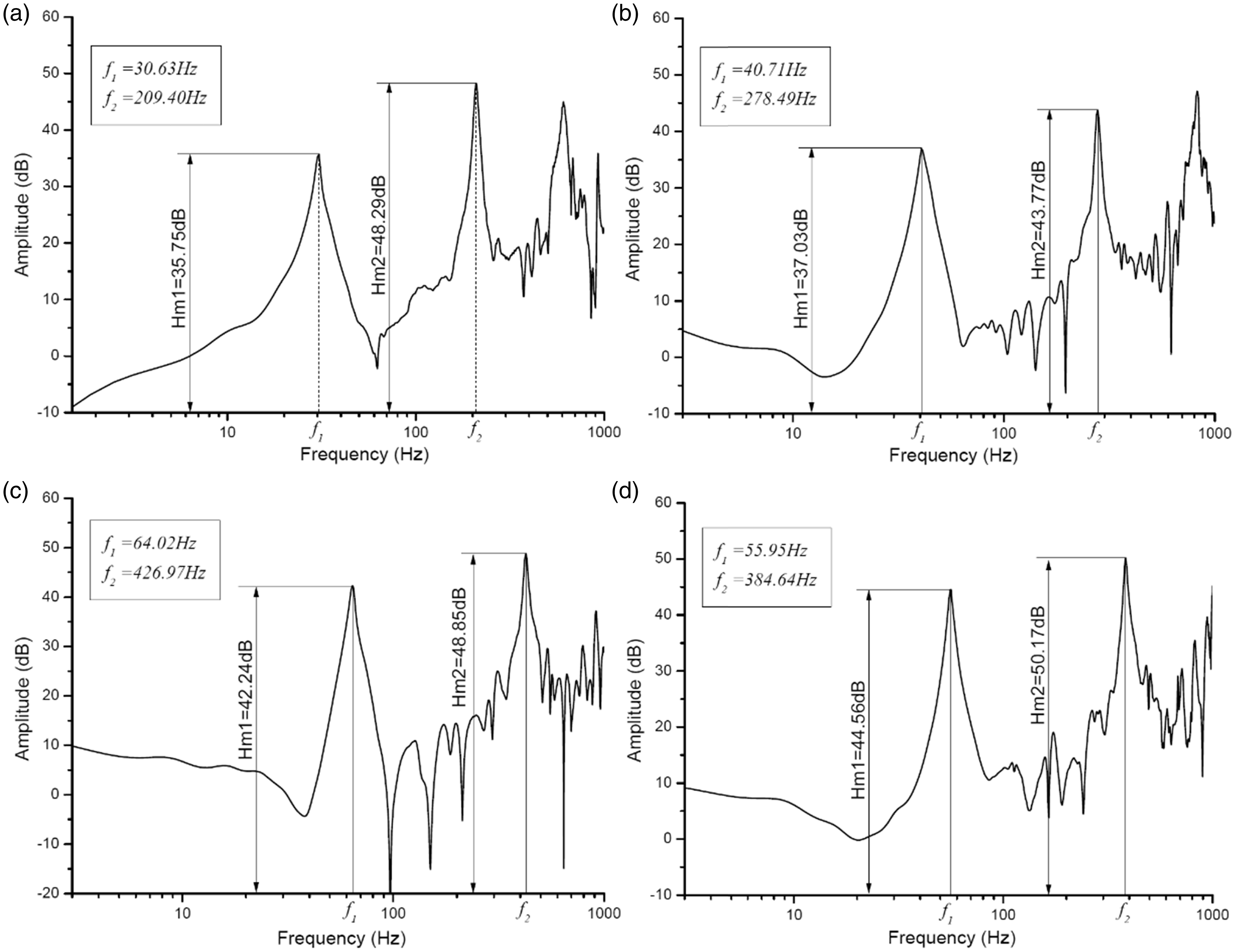
Vibration experiment results. (a) Frequency response curve of Specimen A. (b) Frequency response curve of Specimen B. (c) Frequency response curve of Specimen C. (d) Frequency response curve of Specimen D.
The modal frequency and SDC obtained by the experiment.
Results discussion
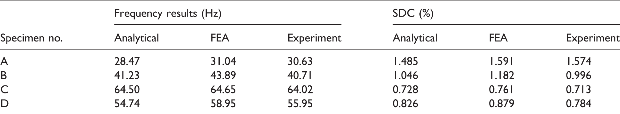
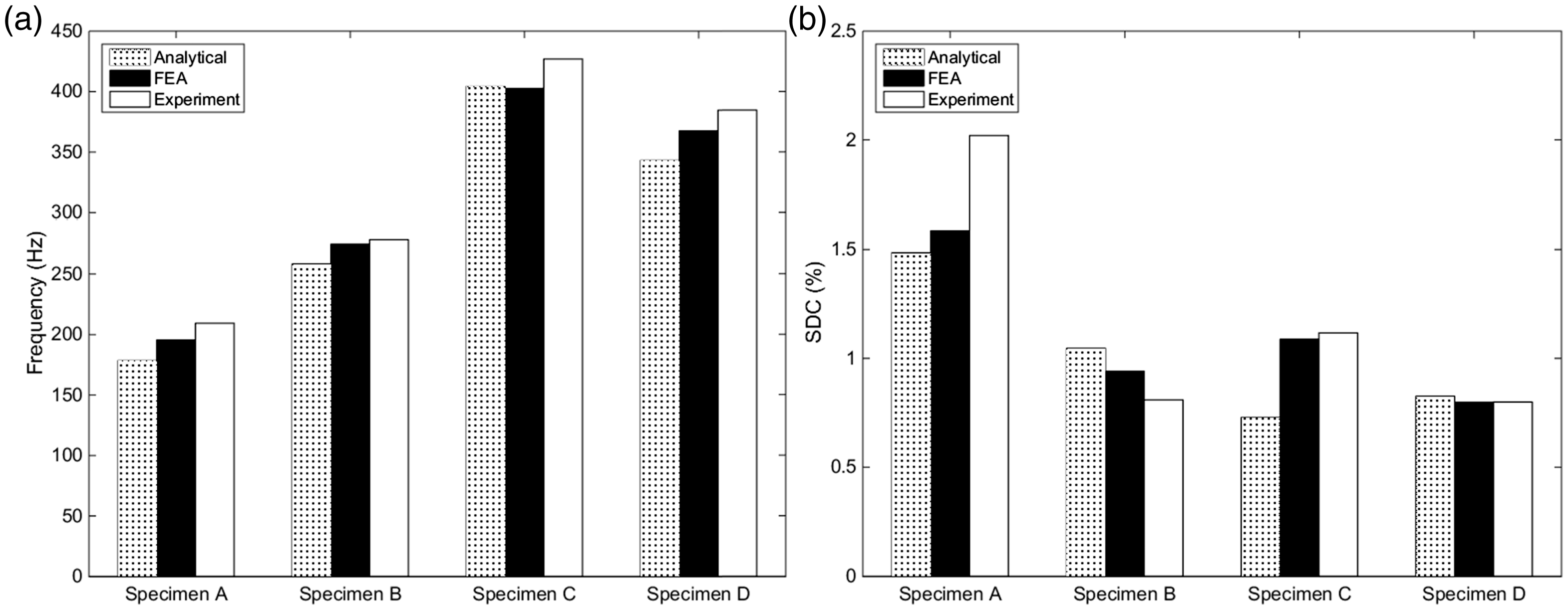
The damping analytical model, the results obtained by the finite element method in literature6,9 and experimental results are shown in Table 6. Figure 7 shows the comparison of the results. It can be seen from Table 6 that the analytical modal has a relatively good accuracy for the prediction of the first-order natural frequency and the SDC of the CFRP beam’s flexural vibration. The maximum error of the first-order flexural natural frequency between the analytical model result and the experimental result is 7.05%, the maximum error of SDC is only 5.65%.
Comparison of experimental, finite element, and analytical results in the first-order mode.
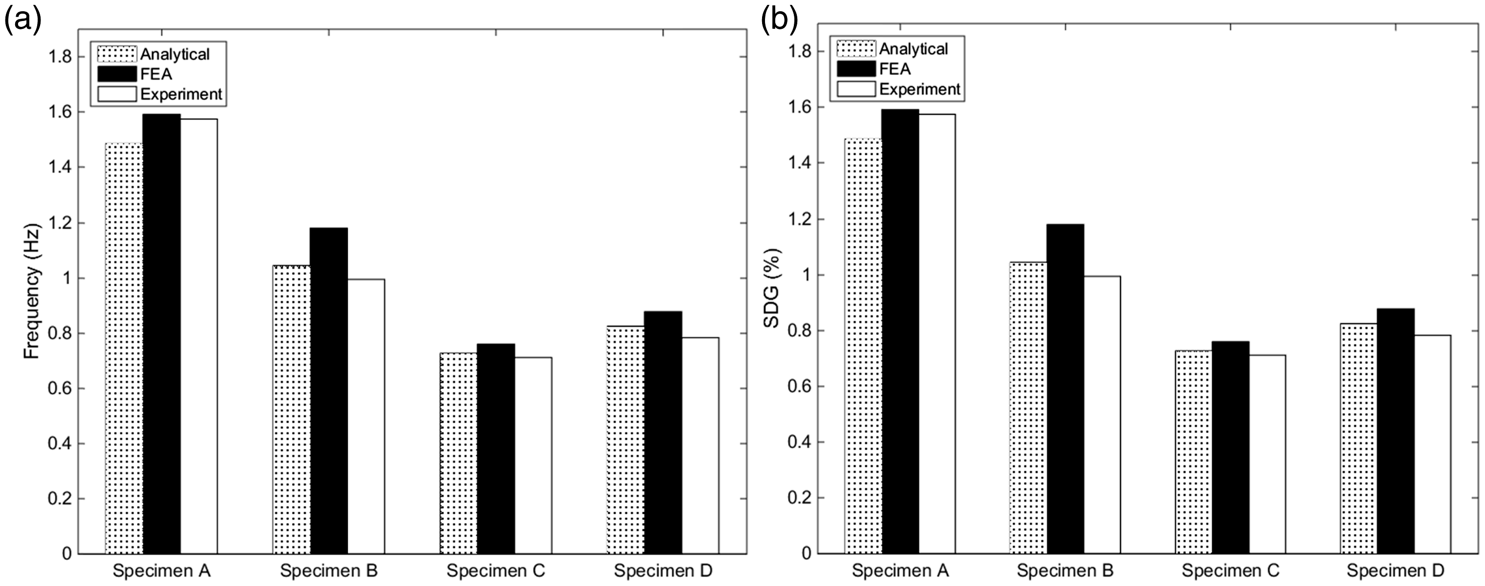
Comparison of the first modal frequency and SDC results of each scheme. (a) Comparison of first modal frequency results and (b) comparison of first modal SDC results.
The maximum error between the FEA method and the experimental result is 7.8% when predicting the CFRP beam’s flexural natural frequency. The FEA method has larger error for the prediction of SDC; the SDC of specimen No. B between the FEA method and the test result is 18.7%. This is because the strain of each layer obtained by the FEA is the average strain of the whole element. The density of the mesh has a great influence on the strain of each element, which will affect the calculation result of the strain energy of the beam.
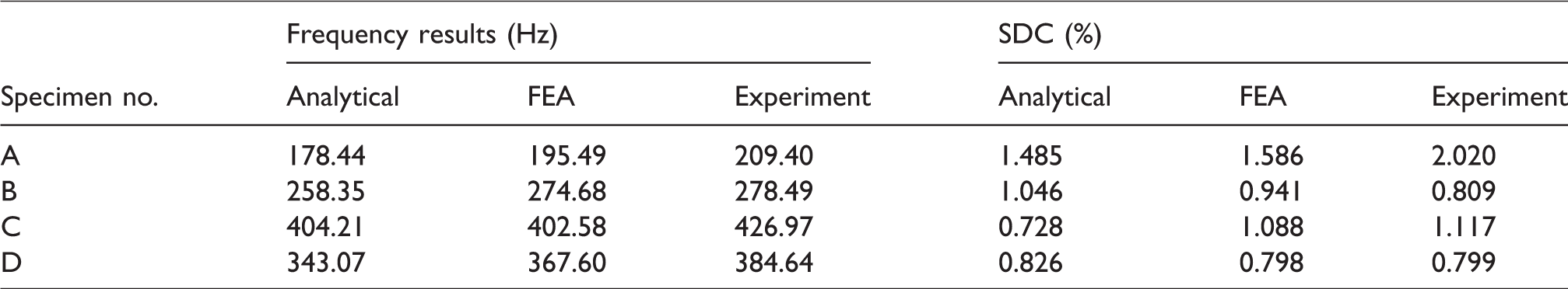
Compared with the first-order mode result, the error of the second-order mode result between the analytical model and the experiment significantly increases (show in Table 7). The maximum error of the second-order mode frequency reaches 14.79%, and the maximum error of the SDC is 34.93%. In the second-order mode, the analytical model cannot predict the flexural vibration SDC of the CFRP beam effectively. This is because the kinematic equation of analytical model is based on Euler–Bernoulli Beam Theory, and this theory does not consider the influence of the CFRP beam cross-section deformation. Besides, the strain energy in thickness, longitudinal, and shear direction of the beam are ignored, which also leads to some error. It can be seen from Figure 8 that the second modal frequency and SDC predicted by FEA agree better with the experiment results than the analytical results. Even though, the error between the FEA and the experiment is relatively big.
Comparison of experimental, finite element, and analytical results in second modality.
Comparison of the second modal frequency and SDC results of each scheme. (a) Comparison of second modal frequency results and (b) comparison of second modal SDC results.
Conclusion
This paper proposed the SDC matrix model of the FRP in the ply level. By combining the laminate theory and Euler–Bernoulli beam theory, the analytical prediction model of the CFRP beam’s flexural vibration SDC was built. Four sets of the CFRP beam specimens with different laminate were designed and manufactured. The flexural vibration test was carried out for each specimen. By comparing the analytical model, the FEA method, and the experimental results, the following conclusions can be obtained:
Compared with the finite element method, the analytical model had higher accuracy for the prediction of the CFRP beam’s flexural vibration’s first-order natural frequency and SDC. The maximum errors of the natural frequency and the SDC were 7.05% and 5.65%, respectively. The SDC of the CFRP beam in a low-frequency flexural vibration can be predicted rapidly, conveniently, and accurately; As the cross-section deformation and longitudinal strain of the beam have not been considered in the analytical model, there are large errors in the prediction of the CFRP beam’s flexural vibration’s second-order natural frequency and SDC.
Footnotes
Declaration of conflicting interests
The author(s) declared no potential conflicts of interest with respect to the research, authorship, and/or publication of this article.
Funding
The author(s) disclosed receipt of the following financial support for the research, authorship, and/or publication of this article: This research was supported by the Fundamental Research Funds for the Central Universities (2017-YB-017), the Fundamental Research Funds for the Central Universities (WUT: 2016III033 and WUT:2016III031), and the National Natural Science Foundation of China (no. U1537103).