
Abstract
Conical shell structures are commonly used in many engineering systems, and vibration suppression is very important to realize the desired function. In this study, piezoelectric ceramics were used as actuators/sensors with a multimodal fuzzy sliding mode controller to suppress vibrations of conical shell structure for the first time. The structure’s natural frequencies and mode shapes were obtained through modal analysis using finite element method and verified by modal tests. The agreement between analysis and test results verified the finite element method was appropriate. A multimodal fuzzy sliding mode controller was subsequently designed based on the analysis to provide active vibration control. The resulting controller was tested experimentally for the conical shell structure. The experimental results indicated that the proposed controller can effectively use to suppress vibration for the conical shell structure.
Introduction
Conical shell structures are widely used in many engineering applications such as marine engineering, aerospace engineering rocket construction, petroleum engineering, civil engineering, and the nuclear industry.1,2 Excessive vibration may lead to abnormal instrument behaviour and operator discomfort. Therefore, it is important to correctly describe a structure’s vibration characteristics and incorporate suitable vibration suppression. Piezoelectric ceramics have excellent high-frequency response, large output torque, and high resolution, and hence are widely used in active vibration control as sensors and actuators.3–6
Many control systems are used for active vibration control such as positive position feedback (PPF), proportional and differential (PD), velocity feedback, linear quadratic regulator (LQR) optimization, sliding mode, and pole placement methods. Wu et al. 7 used velocity feedback control to suppress beam modal vibration. Boz et al. 8 used optimal velocity feedback algorithm on an active vibration control for a plate-like structure. Li et al. 9 proposed a self-adaptive fuzzy sliding mode controller to control beams with uncertain mass. Zorić et al. 10 designed a fuzzy LQR controller for beams, and compared its effectiveness, which were able to achieve vibration suppression better, with an LQR controller. Liu et al. 11 presented active control for nonlinear vibration of beams using optimal delayed feedback controller. Shin et al. 12 investigated active vibration control of clamped–clamped beams using an acceleration feedback controller, the measured results agreed well with theory. Wang et al. 13 adopted a self-adaptive sliding mode control method to achieve effective beam vibration suppression. Sethi et al. 14 researched the vibration characteristics of a frame structure using a system identification method, and implemented multimodal vibration control by pole placement. Qiu et al. 15 studied the locations of piezoelectric ceramics on a plate, and proposed an efficient control method combining PPF and PD. Sohn et al. 16 analyzed the optimal positioning of piezoelectric actuators on a cylinder structure, and adopted LQR for vibration control. Loghmani et al. 17 presented an adaptive feedforward controller based on steepest descent method to control the modal vibration for a cylindrical shell. Kwak and Yang 18 studied the vibration characteristics of a circular cylinder in water and air, and achieved vibration suppression with a harmonic disturbance-accommodating control system. Li et al. 19 designed active vibration control for conical shells using velocity feedback and LQR methods.
There are many advantages and disadvantages to the various approaches. LQR and pole placement methods require an accurate mathematical vibration model. Fuzzy control systems do not require an accurate mathematical model, but generally show poor dynamic responses, while sliding mode control can cause serious chattering. The proposed fuzzy sliding mode controller combines advantages of both fuzzy control and sliding mode control, while compensating for their individual disadvantages, reducing chattering, and providing good dynamic response with improved robustness, and without requiring an accurate mathematical model.
Therefore, active vibration control was applied to a conical shell with piezoelectric sensors and actuators. The vibration mode shapes and natural frequencies were obtained by finite element analysis, and confirmed experimentally by modal tests. Then a fuzzy sliding mode controller was designed based on the analysis to achieve modal vibration control. Experimental results of active vibration control verified the effectiveness of the proposed controller.
Conical shell modal analysis
Theoretical analysis
Mechanical motion due to vibration can be expressed as


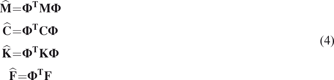

For modal number
Finite element analysis
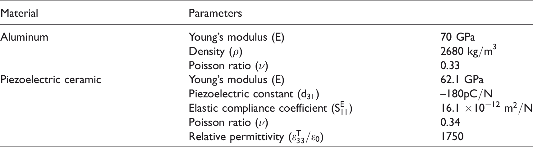
Figure 1 shows the specific object considered, an aluminium conical shell with a fixed small end (diameter 200 mm), big end diameter 300 mm, shell thickness 1 mm, and shell height 500 mm. Two piezoelectric ceramics were symmetrically positioned on the free end as exciter and actuator. The piezoelectric ceramics had length 61 mm, width 35 mm, and thickness 0.5 mm. Two piezoelectric ceramics were positioned as sensors with length 16 mm, width 13 mm, and thickness 0.5 mm. The properties of aluminium and the piezoelectric ceramic material are listed in Table 1.
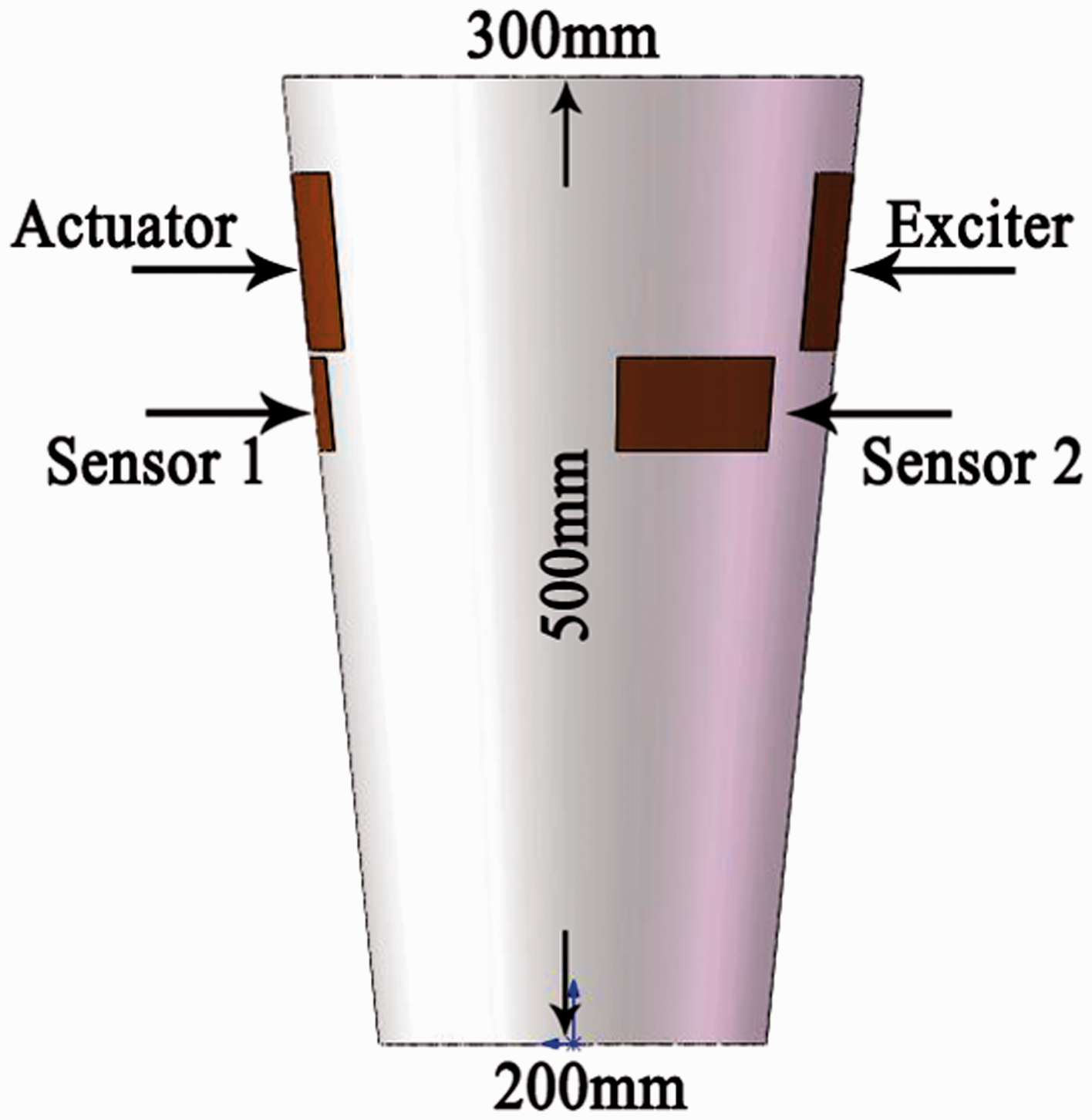
Conical shell used here.
Material properties.
Ignoring the effect of the piezoelectric modules, the first four mode shapes and natural frequencies of the conical shell were obtained using Ansys, which is a widely used finite element analysis software, the analysis results are shown in Figure 2. Finite element analysis which shows the first four natural frequencies are 147.17 Hz, 197.90 Hz, 221.83 Hz, and 299.69 Hz. There are larger strains on the free end in the first, second, and fourth mode, whereas there is little strain on the free end in the third mode. Thus, the piezoelectric ceramics were positioned on the free end of the conical shell.
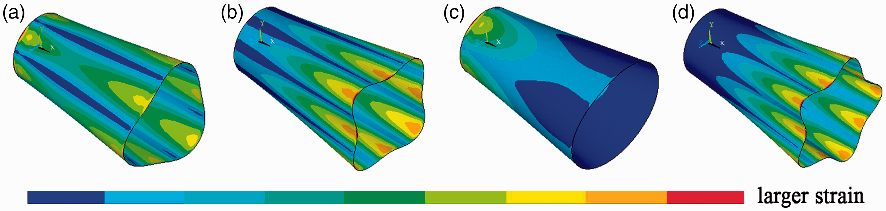
(a) First mode shape, (b) second mode shape, (c) third mode shape, and (d) fourth mode shape of the conical shell.
Modal experiment
The actual modes were measured and identified experimentally19–22 to verify the finite element simulation results and provide further understanding of the structure. The experimental equipment is shown in Figure 3. A sine sweep signal from 50 to 500 Hz was generated from the host computer. The digital signal was transformed to analogue through a D/A module on the slave computer, and the analogue voltage amplified to drive the piezoelectric exciter. Piezoelectric sensors measured the vibration simultaneously, and transmitted the signal to the host computer through the charge amplifier and A/D module.
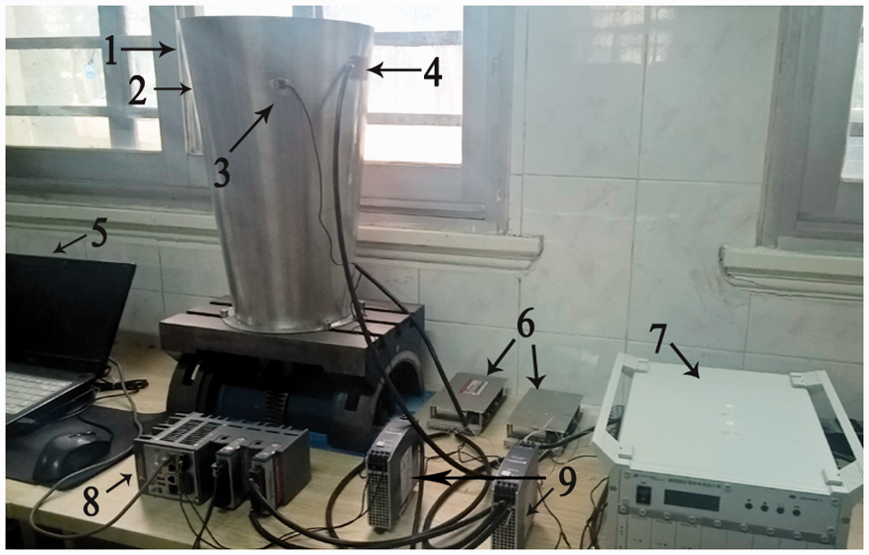
Experimental equipment: (1) Actuator, (2) Sensor 1, (3) Sensor 2, (4) Exciter, (5) Host computer, (6) Voltage amplifier, (7) Charge amplifier, (8) Slave computer, and (9) Power supply.
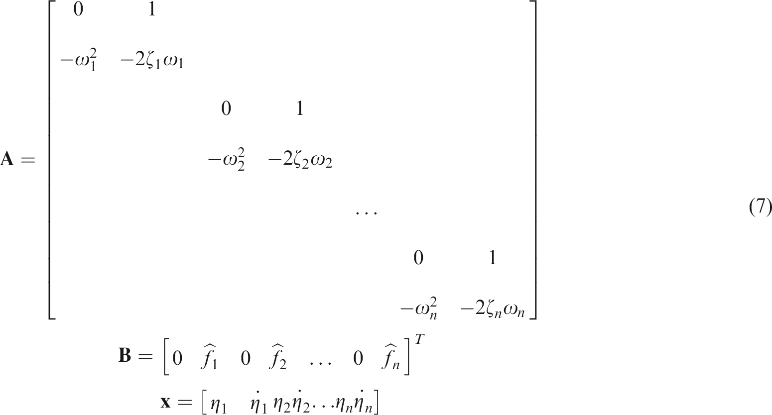
The identified vibration curves are shown in Figure 4: the two different amplitude–frequency curves are from the same exciter and different sensors. Natural frequencies and modal damping ratios were obtained by system identification to provide the parameter values for equation (7).
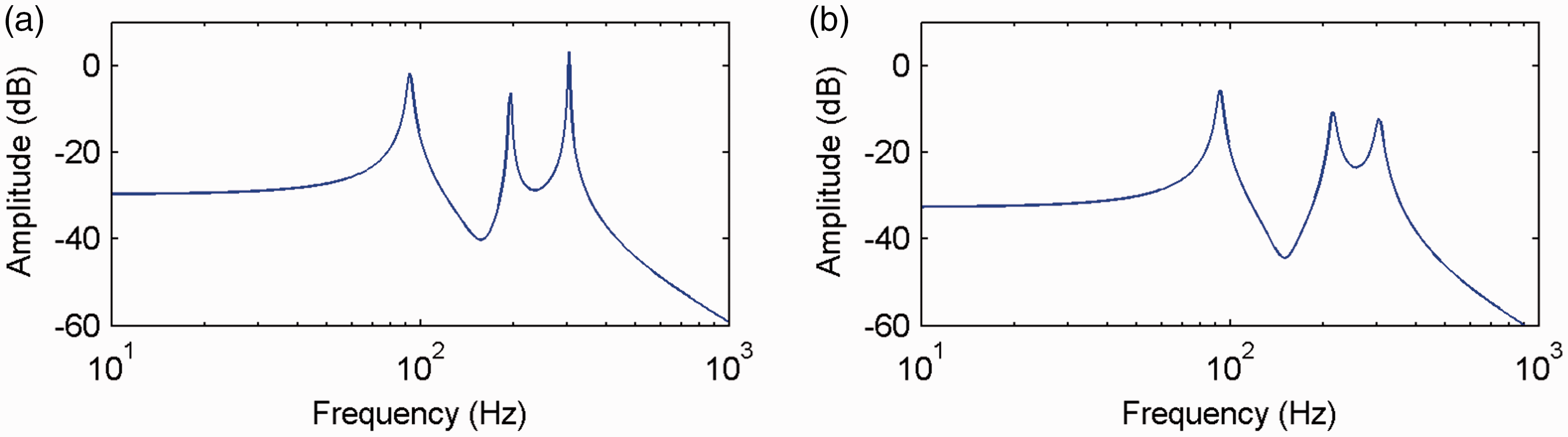
Conical shell vibration curves: (a) Sensor 1 and (b) Sensor 2.
The predicted and measured natural modal frequencies are shown in Table 2. The first, second, and fourth natural modal natural frequencies were identified, but the third modal natural frequency was not evident, for both sensors.
First four modes natural frequencies.
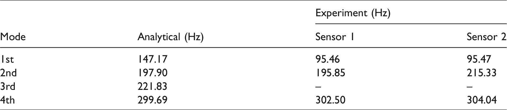
The finite element analysis predicts only a small strain, and hence small disturbance, for the third mode shapes, and so it is difficult to identify the third modal natural frequency at that position. The predicted and measured natural modal frequencies generally show good agreement, although the first frequency has a significant error, which may be caused by machining accuracy and the influence of the piezoelectric ceramics.
Independent modal fuzzy sliding mode control strategy
Sliding mode variable structure control is relatively robust to external disturbances and parameter perturbation, which is the most significant advantage, giving it extensive practicability. Therefore, it is suitable for modelling without requiring an accurate mathematical model.
Assume the sliding surface is


In general, sliding mode dynamics will cause chattering. 24 However, we may adopt fuzzy gain using a fuzzy controller, rather than a fixed gain, to soften the sliding mode controller.
The modal displacement 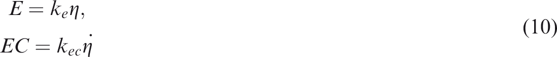
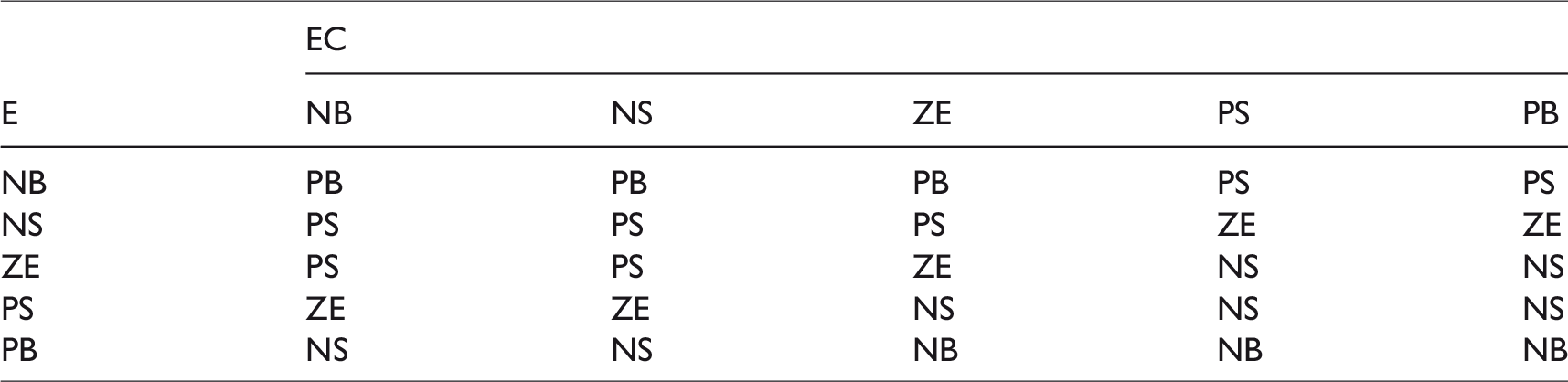
The fuzzy controller receives signal values from the sensor, and transforms them to lingual variables. Five different linguistic terms are corresponded: NB (negative big), NS (negative small), ZE (zero), PS (positive small), PB (positive big). The fuzzy set of input and output variables are both {NB, NS, ZE, PS, and PB}, and the member functions of inputs and outputs are shown in Figure 5. Following the Mamdani method, the fuzzy rules can be expressed as

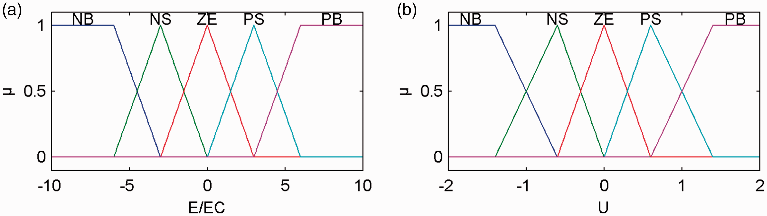
Membership functions: (a) input and (b) output.
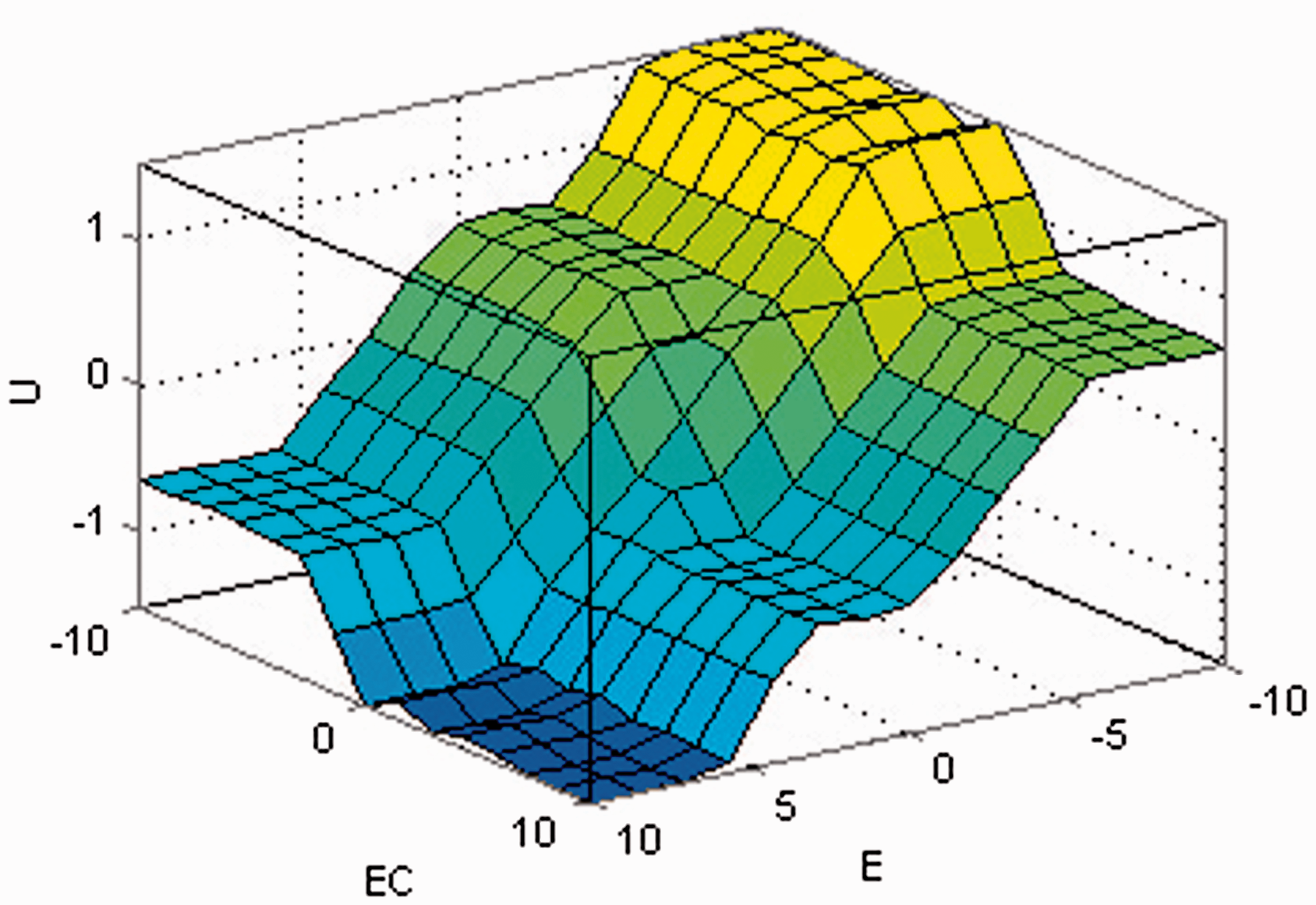
Fuzzy surface corresponding to the defined fuzzy rules.
Fuzzy rules.
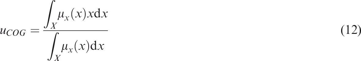
Three methods are commonly used to defuzzify the fuzzy inference to obtain real values: centre of gravity, area bisector, and mean of maxima. Centre of gravity was chosen here

The structure vibration consists of infinite modals, where each modal is decoupled from the others. Modal filtering method was used here to obtain the modal displacement and velocity from sensor voltage. The sensor voltage signals were filtered by band-pass filter near the natural frequencies, then the obtained signals were transformed to displacement and velocity. Therefore, it is convenient to design a modal controller for each modal state independent of the other states, as shown in Figure 7, where
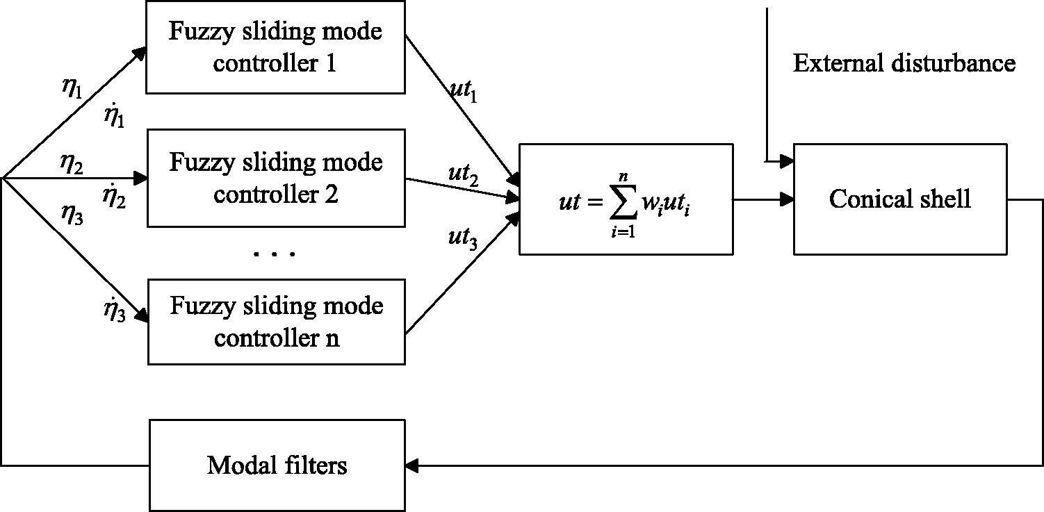
Independent modal fuzzy sliding mode controller.
Experiment
To verify the effectiveness of the proposed control strategy, an active vibration control experiment was performed. Conical shell vibration excitation signals were generated by the slave computer (see Figure 3), through the D/A module, voltage amplifier, and into the piezoelectric exciter. Input signals for the fuzzy sliding mode controller were measured by the piezoelectric sensors. The Linux real time operating system was installed on the slave computer, and Labview was installed on the NI cRIO-9030 host computer. Communication between the slave and host computer was via Ethernet, using a dedicated hub. Figure 8 shows the conical shell frequency domain response for pulse excitation with and without control. The proposed control strategy reduces the first, second and fourth modal vibration amplitudes by 15, 17, and 14 dB, respectively. As discussed above, the third modal vibration is not evident for this system.
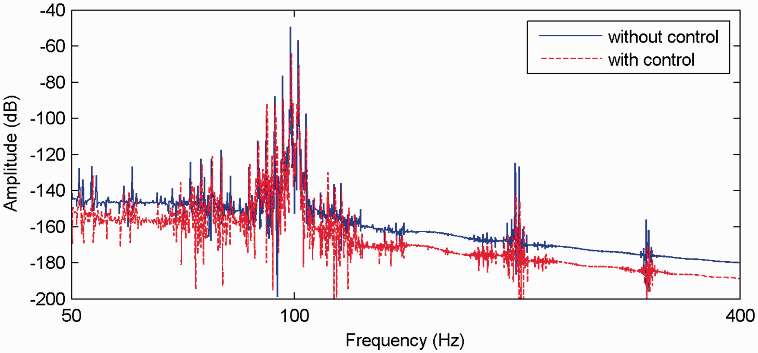
Frequency domain response curves with pulse excitation.
The effect of control for pulse signal excitation with amplitude is 2 V and frequency is 1.2 Hz was examined experimentally. Figure 9 shows the time domain response with and without control, where the designed controller is adopted after 0.8 s. As shown in Figure 9(a), the maximum vibration signal is approximately 0.3 V and 0.2 V without and with control, respectively, showing that vibration has been suppressed by approximately 33% using the proposed controller. Figure 9(c) shows that the maximum vibration signal is approximately 0.15 V and 0.1 V without and with control. Figure 9(d) shows that the maximum vibration signal is approximately 0.07 V and 0.05 V without and with control. Figure 9(e) shows that the maximum vibration signal is approximately 0.045 V and 0.03 V without and with control. This indicated that every modal vibration has been reduced.
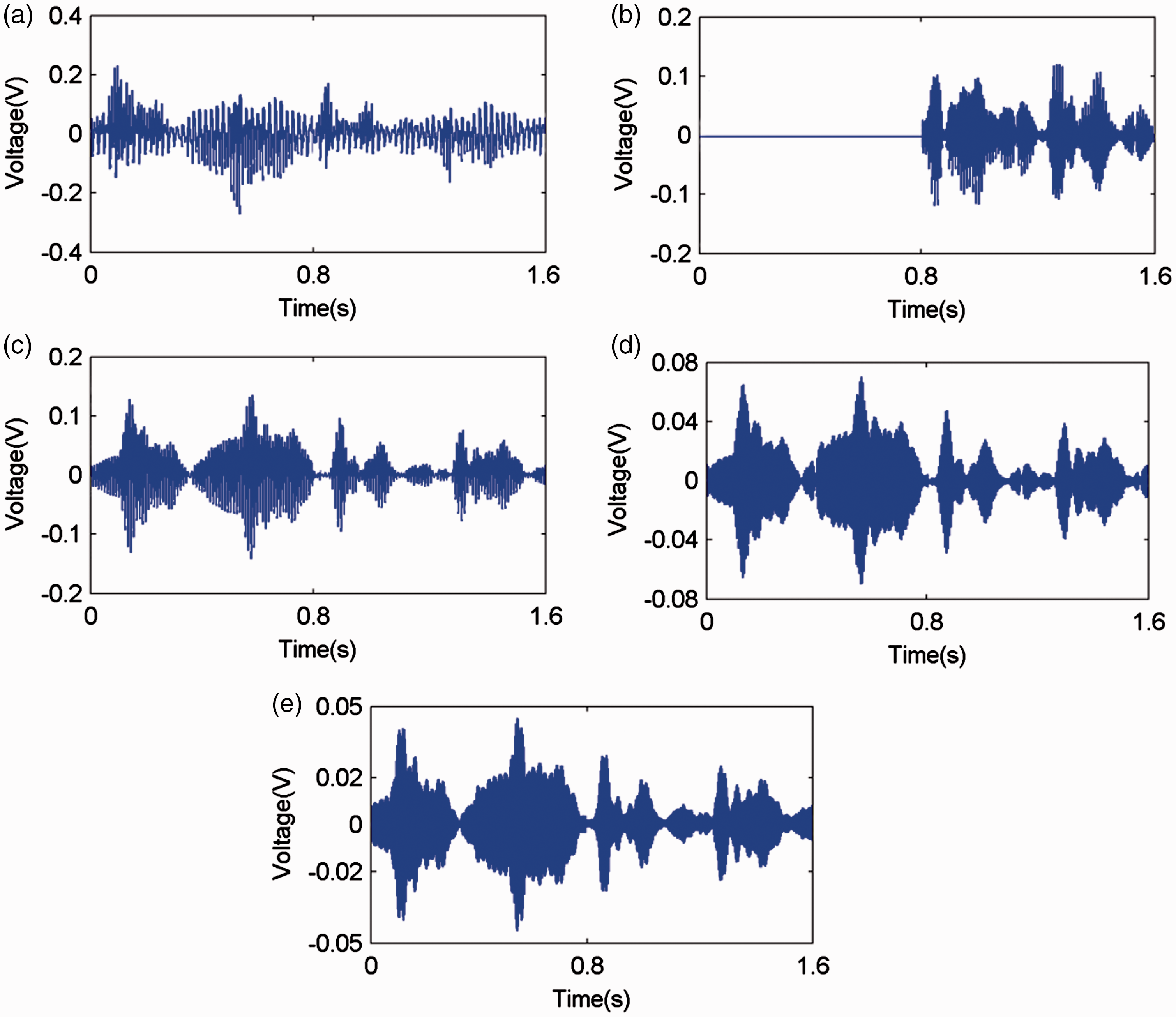
Time domain response curves with pulse excitation: (a) sensor 1 voltage, (b) actuator control voltage, (c) first modal vibration, (d) second modal vibration, and (e) fourth modal vibration.
The effect of control for sinusoidal signal excitation with amplitude is 2 V and frequency is 95.5 Hz was also given here, using the same equipment setup as above (see Figure 3). The time domain response is shown in Figure 10. The designed controller is adopted after 1 s. As shown in Figure 10(a), the maximum vibration signal reduced from 0.23 V to 0.1 V when the proposed controller was applied, i.e. the vibration reduced by approximately 56%, and showed good vibration suppression. As with the previous case, Figure 10(c) shows that the maximum vibration signal is approximately 0.1 V and 0.05 V without and with control. Figure 10(d) shows that the maximum vibration signal is approximately 0.06 V and 0.02 V without and with control. Figure 10(e) shows that the maximum vibration signal is approximately 0.04 V and 0.015 V without and with control. The vibrations were suppressed for every model vibration.
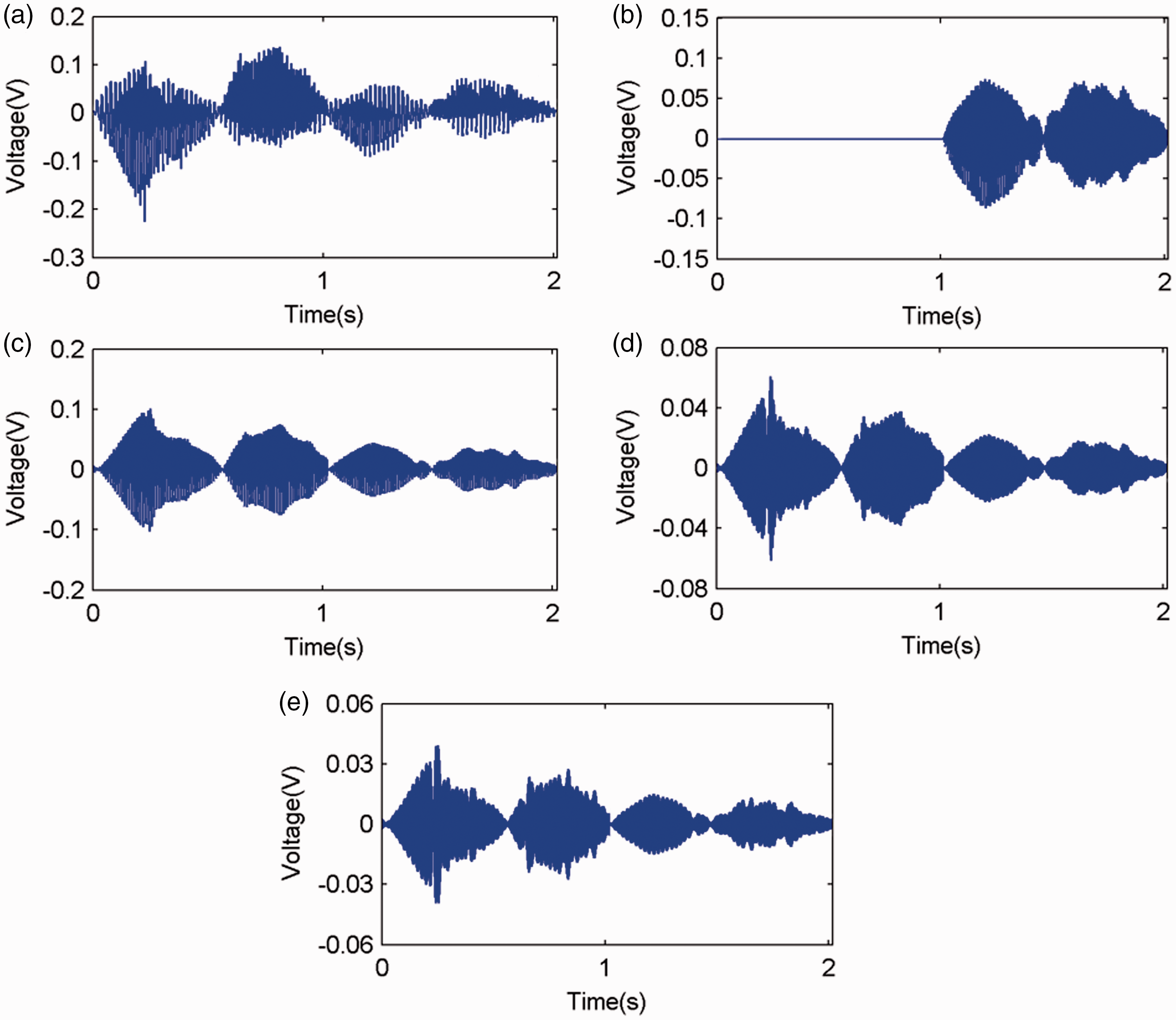
Time domain responses for sinusoidal excitation: (a) sensor 1 voltage, (b) actuator control voltage, (c) first modal vibration, (d) second modal vibration, and (e) fourth modal vibration.
Therefore, designing an effective independent modal fuzzy sliding mode controller does not require an accurate mathematical model. This reduces the design of complex high-order systems to several second-order systems, which greatly simplifies the task. The proposed controller combined the advantages of fuzzy and sliding mode control systems, and shows good vibration suppression and robustness.
Thus, the proposed control strategy is an effective method for vibration suppression in active vibration systems with uncertain disturbances.
Conclusions
The vibration of a conical shell was considered using piezoelectric sensors and actuators. Finite element simulations and modal experiments were employed to obtain the vibration natural frequencies and modal shapes, which provided the basis for positioning the piezoelectric ceramics.
An independent modal fuzzy sliding mode controller was designed to control vibration for each identified mode. Modal vibrations were shown to be decoupled, providing a convenient and flexible way to design each modal vibration controller independently.
The proposed fuzzy sliding mode controller combined the advantages of both fuzzy and sliding mode control, and was verified experimentally to provide good vibration suppression and robustness.
Footnotes
Declaration of conflicting interests
The author(s) declared no potential conflicts of interest with respect to the research, authorship, and/or publication of this article.
Funding
The author(s) received no financial support for the research, authorship, and/or publication of this article.