
Abstract
Transmission of a sound generated by a localized point source in the air through a realistic sea surface is studied by the use of the Kirchhoff-Helmholtz integral. An earlier approach had been based on the Kirchhoff-Helmholtz integral which only considered the effects of rough surface. In the current study, not only the effect of the rough surface is taken into account but also the effects of subsurface bubbles are included in modeling the real phenomenon more accurately. In order to include the effects of subsurface bubble population, the classic relations of the Kirchhoff-Helmholtz integral are reformulated. Accordingly, a three-phase region of air, water, and bubbly water at the sea surface is analyzed, and the rough interface of bubbly water–air is discretized. Through considering an element area Ai, the transmission coefficient
Keywords
Introduction
Transmission of sound through water–air interface is often considered as an example of the application of Snell’s law and Fresnel reflection and transmission coefficients
1
in the acoustic textbooks. Studying the sound transmission between air and water is mostly conducted under the greatly simplifying assumption of smooth interface between the sea water (density:
In recent years, the anomalous transparency1,3–5 and enhanced sound transmission6–8 theories for sound transmission through air–water interface have been introduced. In these theories, despite the mentioning of the classical view of air–water interface, it is anticipated that most of the acoustic power in a liquid half-space for a low frequency sound generated near the interface within a fraction of wavelength can be radiated into a gas half-space. 5 Through some experimental studies, Calvo et al. 7 checked the accuracy of the mentioned theories for a smooth air–water interface. However, the anomalous transparency predictions exceed beyond the smooth air–water interface and even anticipate that rough air–water interface does not have significant effects on the anomalous transparency of the air–water interface. Although these theories suggest a new approach towards sound transmission through the air–water interface, for practical applications in the ocean, it is imperative to consider a more realistic air–water interface for obtaining accurate solutions. There are other theoretical9–28 and experimental15,19,24,26,28,29–34 approaches for sound transmission or/and scattering which consider the water–air interface which focus on the acoustic field in water due to the existence of powerful airborne noise sources such as helicopters,31–33 propeller-driven aircraft26–28,34 and supersonic transport.24,25,27,28,35
Medwin and Hagy, 36 by solving Helmholtz integral and deriving the transmitted pressure to the second medium, studied sound transmission through air–water rough interface. Medwin et al., 37 by conducting FLIPEX I and II experimental tests, examined the low frequency (ranging from 50 Hz to 1000 Hz) sound transmission as a function of different variables such as incident angle, frequency, source and receiver position ratio, and surface acoustical roughness. However, their theoretical approach underestimated the transmission change (TC) in some cases, compared to that of experimental data. The TC parameter is applied for defining the ratio of the transmitted pressure (in the second medium) to the incident pressure in the first medium in logarithmic unit.
Ogden and Erskine38,39 and Nicholas et al., 40 based on Critical Sea Tests 1–7 (CST 1–7), identified three regimes for the companion problem of the sound transmission which was sound scattering from air–water interface at the sea surface. Based on their conclusions, each regime is controlled by two mechanisms: subsurface bubble clouds and surface geometric roughness. Ogden and Erskine 39 emphasized that both the stated mechanisms should be considered in order to obtain accurate scattering strength coefficients. Since scattering and transmission of sound are considered companion problems 36 and their corresponding pressure fields can be derived for the same initial source pressure by the Helmholtz-Kirchhoff integral, in the current paper, both mechanisms that were identified for sound scattering from the sea surface are considered in order to examine sound transmission through a realistic air–water interface in the ocean.
As pointed out earlier, the earlier approach adopted by Medwin and Hagy 36 was based on the Kirchhoff-Helmholtz integral and only considered the effects of rough surface. However, in the current study, not only the effect of rough surface is considered but also the effects of subsurface bubbles are included for a more precise modeling of the real phenomenon. In order to include the effects of subsurface bubble population, the classic relations of the Kirchhoff-Helmholtz integral are reformulated and both mechanisms of the subsurface bubble clouds and surface geometric roughness in the sound transmission are taken into consideration through a realistic air–water interface. Then, the TC equation is derived. Subsequently, an algorithm is presented in the following section for numerically solving the derived equation for TC. Then, numerical results of TC are validated against FLIPEX I and II experimental data. Finally, a set of parametric studies is conducted.
Sound transmission through air–water interface
If a continuous wave of frequency

Geometry of sound transmission through interface air–water.
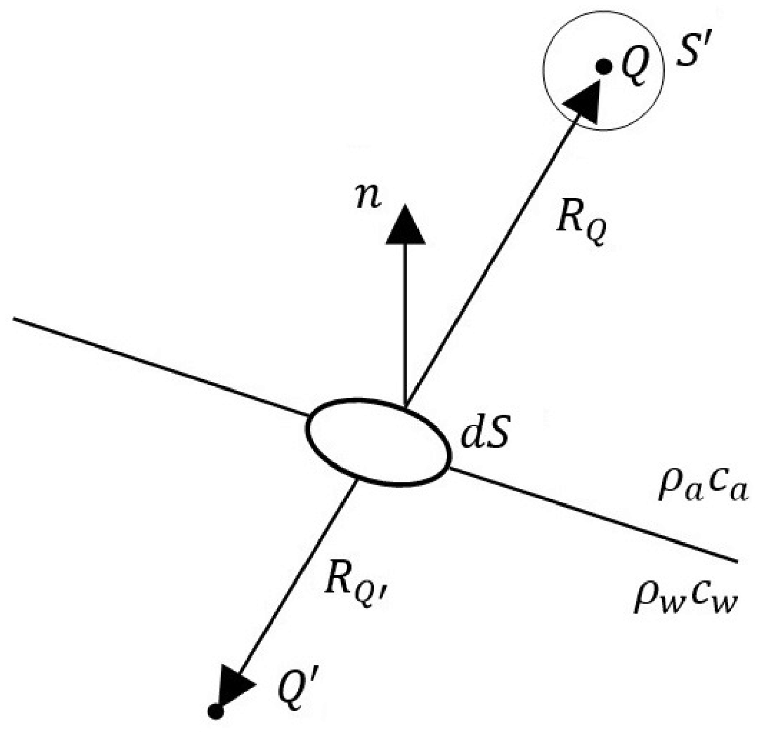
The source singularity effect, Q, is omitted by enclosing it within the surface

As discussed by Medwin and Clay,
2

The integral in equation (3) is the integral theorem of Helmholtz and Kirchhoff for the harmonic sources, and S is an element of the ocean surface or an element on the surface of a scatterer in the volume. If an artifice of transmitting a ping that is short enough to separate the direct and scattered arrivals and still long enough to permit the application of CW theory is used, then the field at Q is determined by the sound which is scattered from the surface elements alone. This is due to the fact that contribution from the source is not present at Q, when the scattered signal is observed.
2
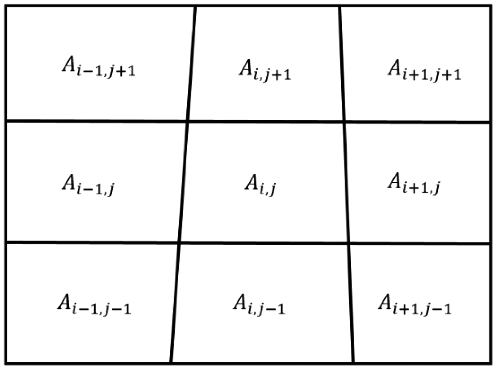
Meanwhile, it is possible to use equation (3) to calculate the transmitted sound for a surface element. The geometry is illustrated in Figure 1. The boundary condition for the outward-traveling wave is
2


Hence, by utilizing equation (4), the transmitted wave can be expanded and written for the water medium as follows


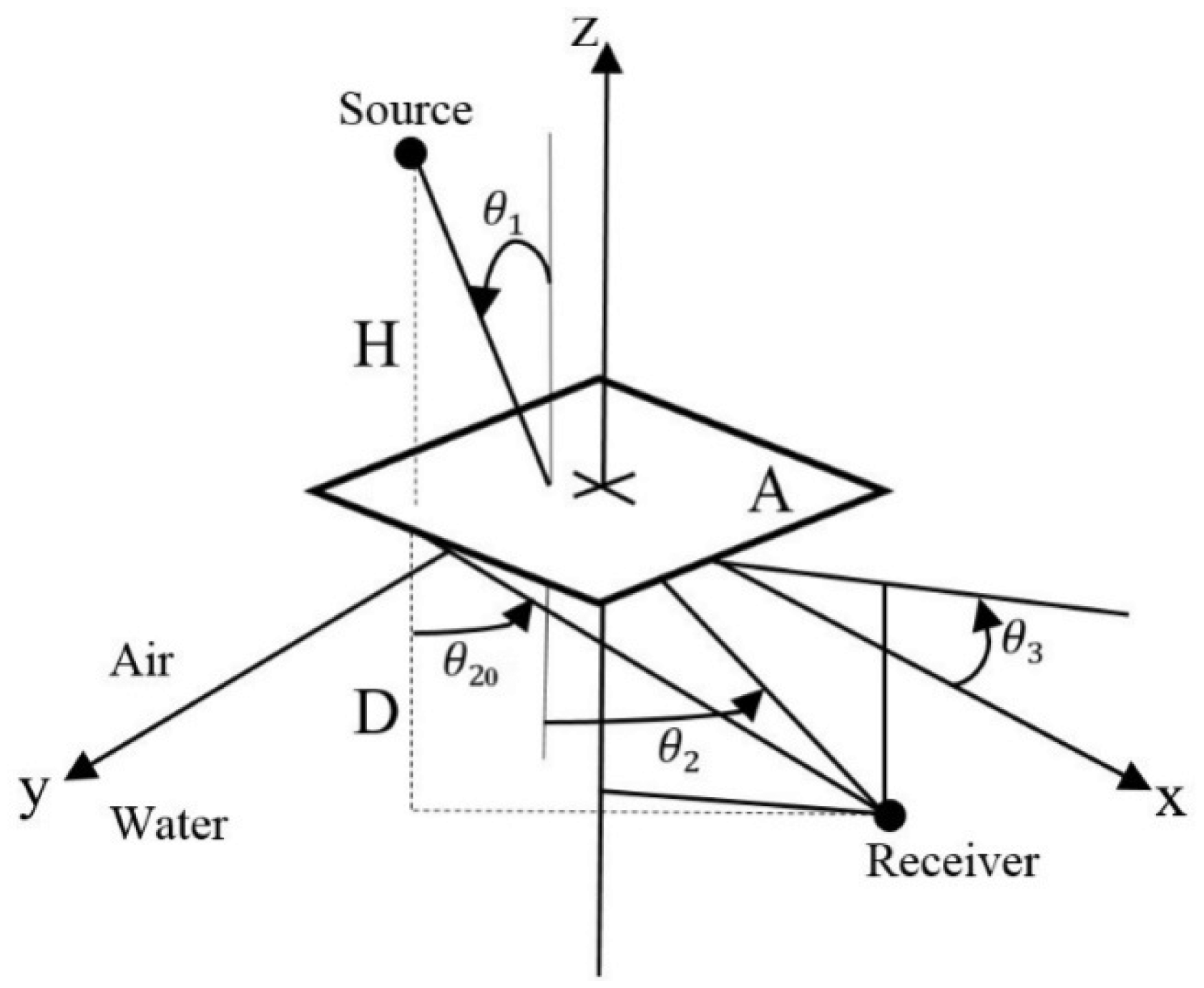
Illustration of sound transmission into water from a localized point source in the air.
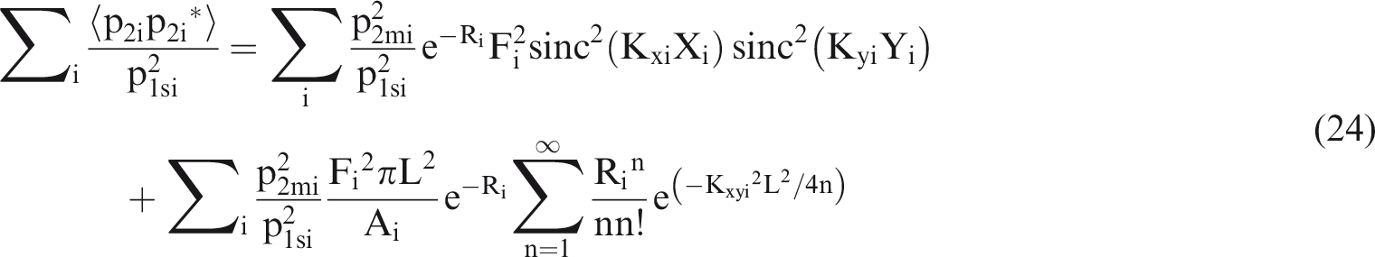
Here, L is the sea surface correlation length. By utilizing the series expansion for the exponential function and integration, the variance of

Therefore, the total relative intensity is obtained by adding the square of equations (17) to (21) and dividing by


When the point source emits sound towards a rough sea surface, the incoherent component of equation (22) can be dominant. In order to obtain the incoherent term of equation (22), the insonified area on the rough air–water interface, i.e. A, should be divided into subsurfaces and all the incoherent contributions should be added.
39
The requirements for each subarea are: (a) the incident pressure is approximately constant, (b) the spatial variation of the incident phase is negligible (e.g. less than one eighth of a wave length λ), and (c) the linear dimension of the subarea is several correlation lengths in extent.
36
By utilizing equation (21), assumptions (a) and (b) are satisfied. Based on the assumption (c), the spatial correlation should reach a small value to accomplish infinite integral of equation (21). Hence, for a point source, equation (22) can be applied for transmission through an element of area


This sum is the Kirchhoff-Helmholtz formulation of the relatively transmitted coherent intensity of a point source for a mirror surface. Therefore, the relative coherent transmission along the Snell direction can be obtained as

For the incoherent term, function

The function

Considering


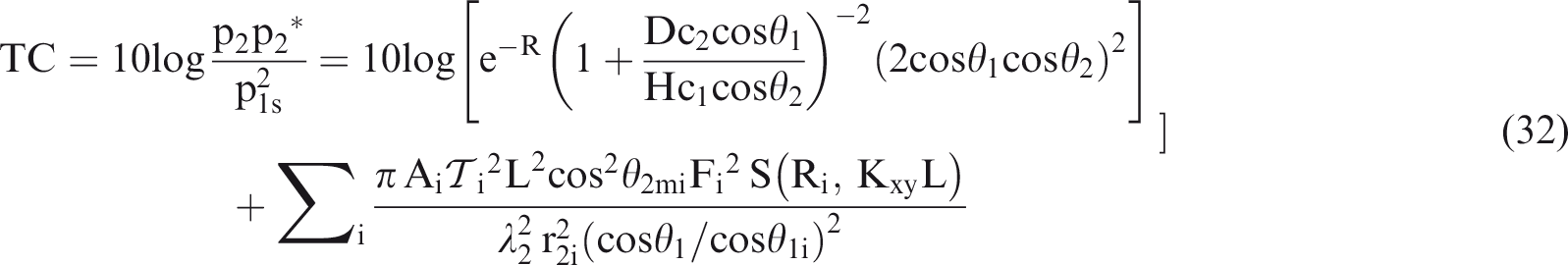
Equation (32) states that, for very low frequencies (R<<1), the summation (incoherent) term will be very small,
Simulation of the problem
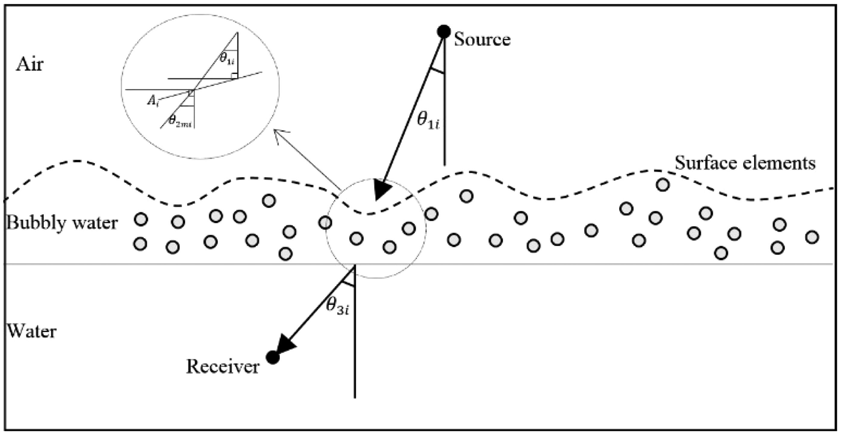
In ‘Sound transmission through air–water interface’ section, equation (32) which is the summation of coherent and incoherent terms was derived. Coherent term can be calculated easily, but to obtain the incoherent term, it is necessary to divide rough interface into subareas. On the other hand, the effects of subsurface bubble clouds should be involved in TC relation. Therefore, a third medium besides the air and water media named bubbly water medium is considered below the rough interface (Figure 3). Incoherent term contains both surface geometric roughness and subsurface bubble clouds’ mechanisms. Subsurface bubble clouds through

Schematic of the sound transmission through a realistic air–water interface at the sea surface.
Required information for each subarea
In order to determine the appropriate value of the incoherent term, two mechanisms of surface geometric roughness and subsurface bubble clouds should be determined for each surface element. Therefore, the modeling procedure of sound transmission through rough bubbly air–water interface is separately presented for each mechanism in the following subsections.
Modeling the rough surface
When the emitted sound from a localized point source in the air strikes the rough bubbly air–water interface, based on the incoherent term of equation (32), the transmitted sound to the next medium passes through the considered subareas on the rough interface. For each subarea Ai, the designated information in Table 1 should be determined. Each surface element depending on its features plays an individual role in sound transmission. Medwin and Hagy
36
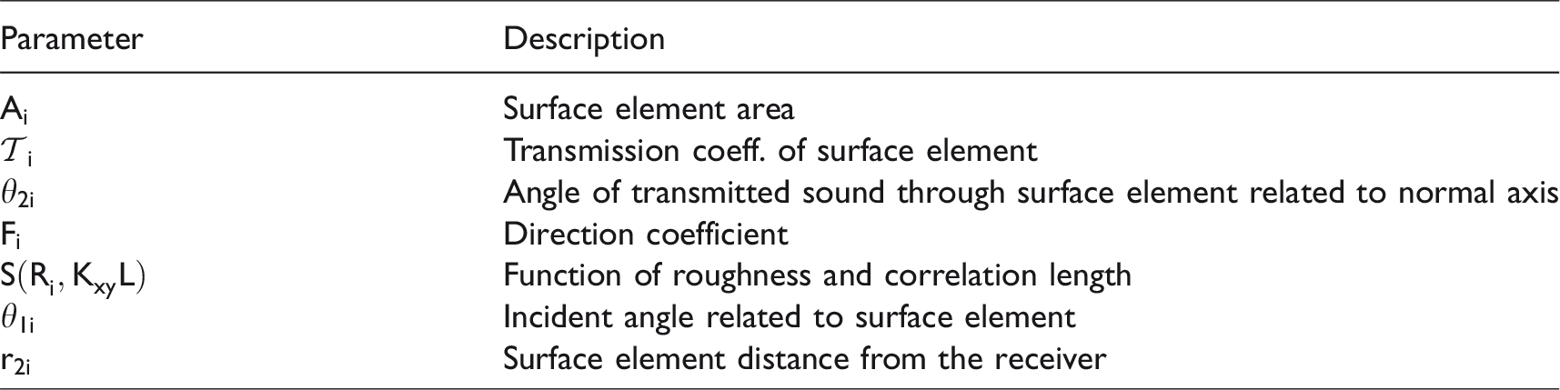
pointed out that dimensions of the surface elements should be determined in a way that two conditions are satisfied. First, the incident sound wave should have uniform phase and amplitude over the elements. Second, the correlation on the boundary of the subareas must become effectively zero. Since the rough interface is divided into elements which can be geometrically irregular, the element mean width is considered to be
Part of the discretized rough surface and arrangement of elements. Indices
Geometry of the rough surface transmission for a point source in the air.
Modeling the bubbles
Due to the presence of waves (rough interface of air–water, in acoustical point of view) in the real sea surface, subsurface bubble clouds are generated as a result of breaking waves. This thin layer of bubbles below air–water interface can affect the properties of the passing sound and is considered as an important factor for the sea surface in underwater acoustics.
2
This layer of bubbles was not considered by Medwin and Hagy
36
in studying the sound transmission through a real air–water interface in the ocean. As described in the next sections, the results of Medwin and Hagy
36
underestimate the TC values compared to the experimental results. The current authors believe that this underestimation is largely due to the omission of the subsurface bubble clouds’ effects. Subsurface bubble cloud, as Ogden and Erskine38,39 stated, is an individual mechanism in a real sea surface which should be considered in order to determine the sound quality in this region. Therefore, due to the importance of subsurface bubble clouds, this layer is considered as the third medium of the bubbly water (other than air and water media) with its own physical properties such as density
As mentioned earlier, subsurface bubble clouds through component 


Sound transmission through elements of the rough interface and the Snell’s ray direction.
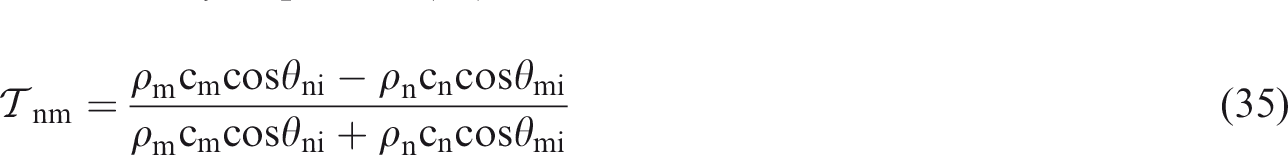
Here, n and m are the corresponding indices 1, 2, or 3 for the air, bubbly water, and water, respectively (for the bubbly water medium, index
Sound speed is determined by considering the significant effects of the subsurface bubble plumes on the sound speed and attenuation. According to Van Vossen and Ainslie,
41
sound speed in the bubbly water can be determined by the relation
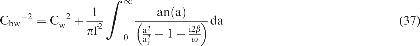

Von Vossen and Ainslie
41
proposed a model called extended HN model in which bubbles with larger radius are considered through modifying the term 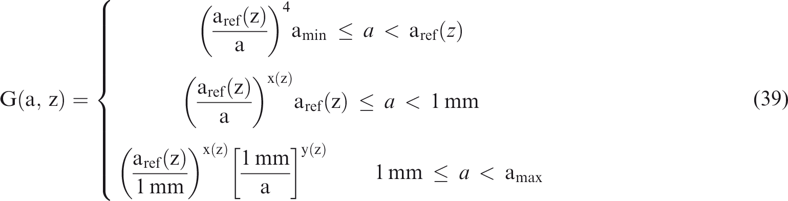

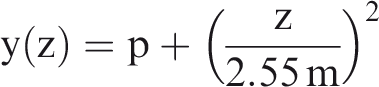
The constant parameter p has been called tuning parameter by von Vossen and Ainslie 41 and can be determined by fitting the data. When the sound speed in the bubbly water is determined, it would then be possible to find the reflection and transmission coefficients based on equations (35) and (36), respectively. Van Vossen and Ainslie 41 explained the detailed process of determining the population of the bubbles based on equation (38). The same approach is adopted in the current paper and Table 2 presents the outcome of the computations based on the Van Vossen and Ainslie’s approach.
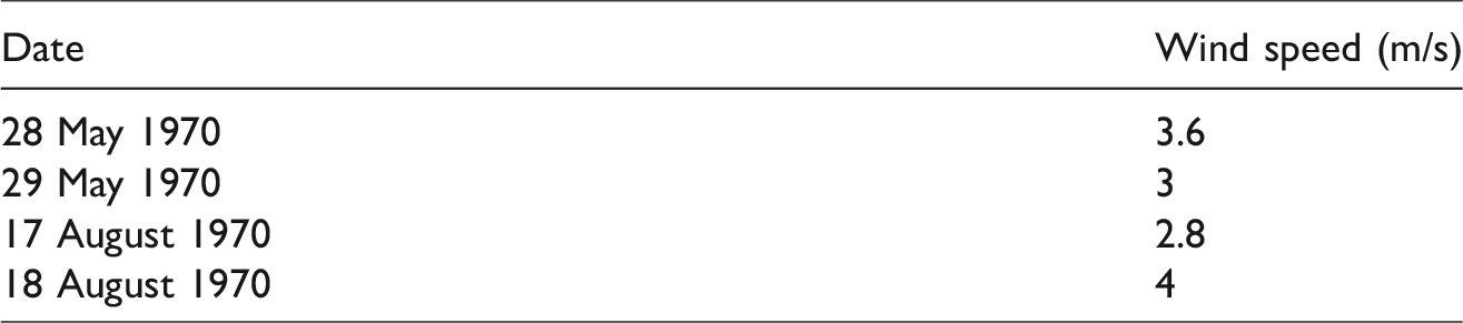
Wind speed information on dates of FLIPEX tests.42
The density of bubbly water medium can be determined as follows

Here, the subsurface bubble properties should be determined based on FLIPEX experimental tests. FLIPEX I experiment (May 1970) and FLIPEX II experiment (August 1970) were performed at a deep sea location 4 and 5 miles NW of San Diego. 37 Table 2 shows the wind speed information related to the mentioned dates.
The integrated bubble PSD at the minimum and maximum wind speeds of the FLIPEX I and II experimental tests are shown in Figure 7. Through PSD, it is possible to obtain
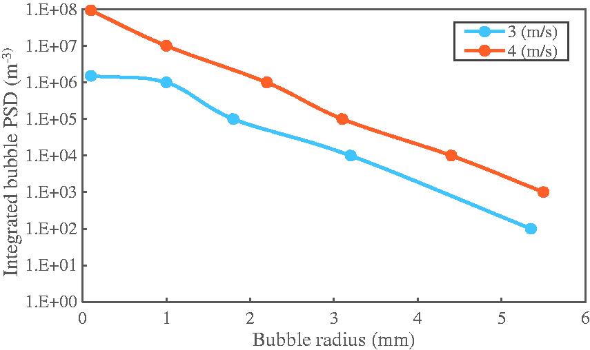
Integrated bubble PSD for the extended HN model based on the conditions of FLIPEX I and II experimental tests.
Algorithm for computing the TC
The required relations and information for computing the TC were presented in the previous sections. Accordingly, it is possible to compute TC by considering two various essential mechanisms of subsurface bubble clouds and surface geometric roughness. The general procedure for calculating TC is shown in Figure 8. Based on the algorithm in Figure 8, sound transmission through air–water and bubbly water interface at the sea surface is simulated by a developed code in FORTRAN programming language which is named Sound Transmission Simulator through Sea Surface (STSSS).
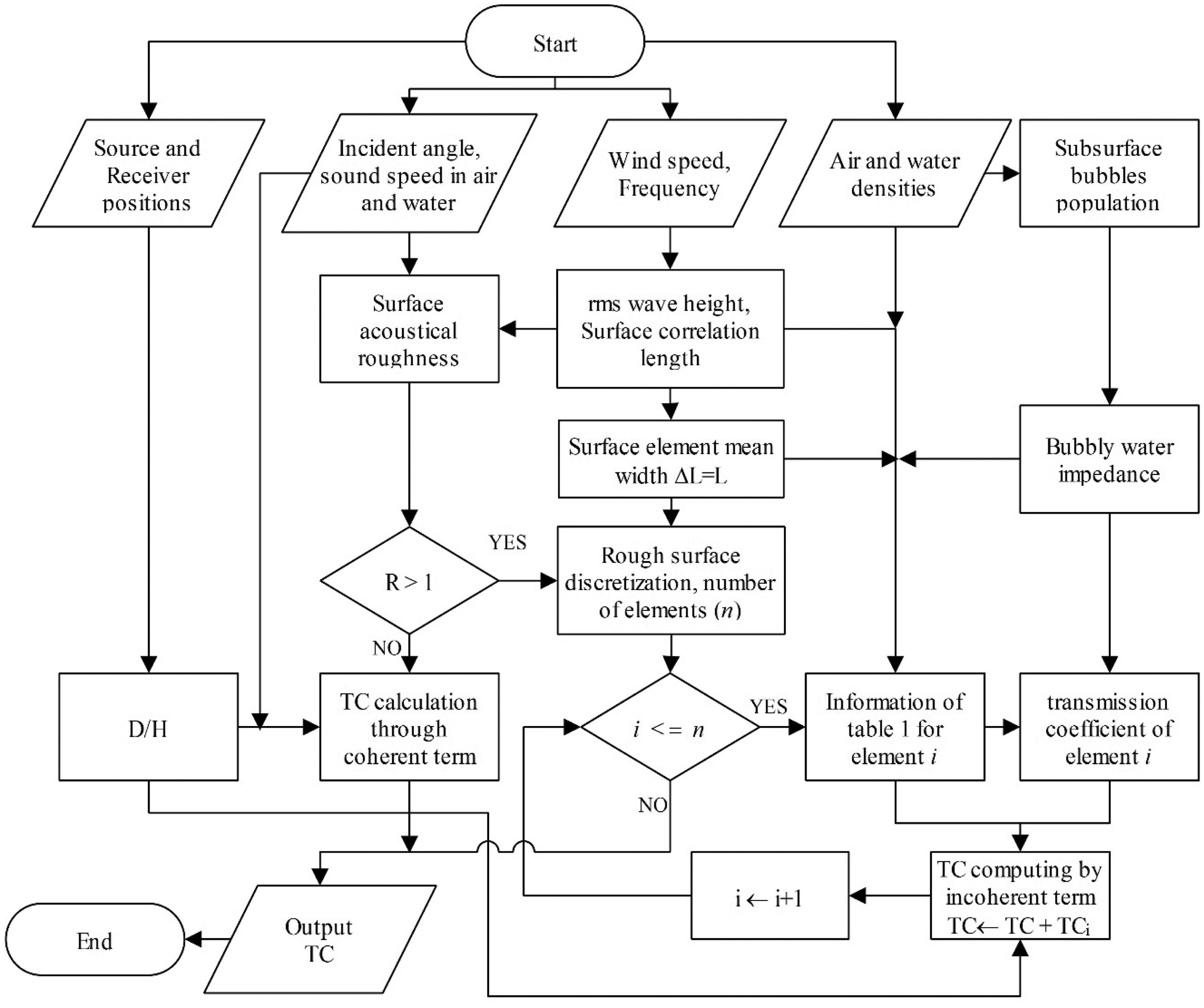
Flowchart of the Sound Transmission Simulator through Sea Surface (STSSS) program (i is the element’s node and n is the total number of surface elements).
Parametric study
As stated in the previous section, two different mechanisms can be considered for sound transmission through rough bubbly air–water interface. When the surface is smooth (i.e. R≪1), the coherent term based on equation (32) is important. Therefore, TC is due to geometry and the impedance mismatch, and the incoherent term can be neglected. Figure 9 presents FLIPEX II experimental tests and theoretical data of TC versus D/H ratio at a constant normal incidence. In these data sets, source height is considered to be 180 m above the sea surface and the surface acoustical roughness R for the normal incident sound is assumed to be 0.15 and
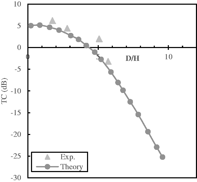
Variation of TC as a function D/H ratio, for sound propagating at normal incidence and very small acoustic roughness
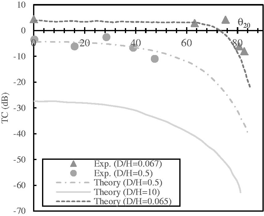
Variation of TC as a function of angle
Knowing the wind speed over the sea surface makes it possible to find the surface height correlation length, L. For instance, Cox and Munk
44
through obtaining the RMS slope of the sea surface as a function of wind speed, calculated the Gaussian correlation length, L. Since the experimental results of FLIPEX tests are considered in this paper, the corresponding correlation length
TC calculated by equation (35) as a function of frequency for a randomly rough ocean surface of RMS height
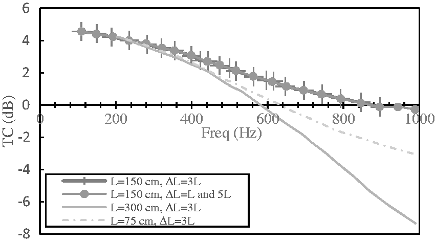
Therefore, in order to check these conditions, Medwin and Hagy
36
studied TC values in different correlation length, L and the elements mean width
As pointed out earlier, Medwin and Hagy 36 only considered the surface geometric roughness effects on the sound transmission and in their theoretical approach, the effects of subsurface bubble clouds were neglected. Also, through FLIPEX II experimental field study, they reported TC values in different conditions, but their theoretical approach underestimated the TC in some cases. In the current paper, due to the important role of the subsurface bubble clouds in sound transmission, the influence of this thin layer on TC is taken into consideration in equation (32) through component of the transmission coefficient. Since the incoherent term of equation (32) for the surface acoustical roughness, R>1, is dominant, it is necessary to determine the TC values by considering two mentioned mechanisms effects.
In order to perform the numerical simulation based on FLIPEX II setups, the rough sea surface is discretized according to its surface correlation length, surface RMS height, and surface element mean width, as shown in Figure 12. Based on Figure 11, the variation of the correlation length has much more effect on the TC, compared to that of elements mean width. Based on the results in Figure 11, it can be seen that there is no linear relationship between the surface correlation length and the TC. In fact, since TC variation depends on other environmental conditions such as sea surface height, wind speed and also on the point source height and receiver’s position during the tests, one cannot conclude how surface correlation length variation affects the TC. However, as shown in Figure 11, it can be concluded that variation of the elements mean width
Schematic of sea surface discretisization (x and y axes scale are
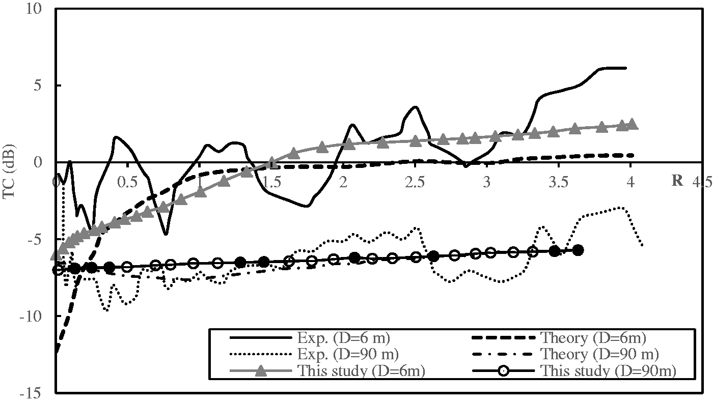
TC as a function of surface acoustical roughness, in two different D/H ratios 0.067 and 0.5, surface correlation length and RMS wave height are considered 1.5 m and 0.13 cm, respectively.
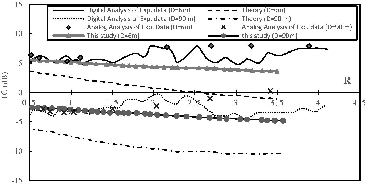
Figure 14 shows the TC values in a condition that the point source is not directly over the receiver position. In this case, point source is in the air and is offset by 75 m from the position of receivers. Therefore, the two considered receivers in 6 m and 90 m depths in FLIPEX II setups are at angles
TC as a function of surface acoustical roughness,
Since in this study, wind-generated bubbles are considered, the subsurface bubbles’ population is a function of wind speed (equation (37)). Also the population of bubbles in the bubbly water medium determines the density and sound speed or impedance of this medium. Therefore, in Figure 15, TC is studied at different wind speeds 5 m/s, 10 m/s, 15 m/s and for two various D/H ratios 0.065 and 0.5 in order to examine the subsurface bubble population effects. Frequency range is considered between 50 and 1000 Hz. Based on the presented results in Figure 15, it can be seen that as wind the speed increases, which implies an increase in the subsurface bubbles’ population and surface RMS height, for a constant D/H ratio, the TC decreases. Also, when D/H ratio increases at the same wind speeds and frequency range, TC decreases again. Reduction of TC values at a constant wind speeds and D/H ratios, as the acoustical roughness increases due to variation of frequency within the considered spectral region 50–1000 Hz, can be observed in the presented curves of Figure 15.
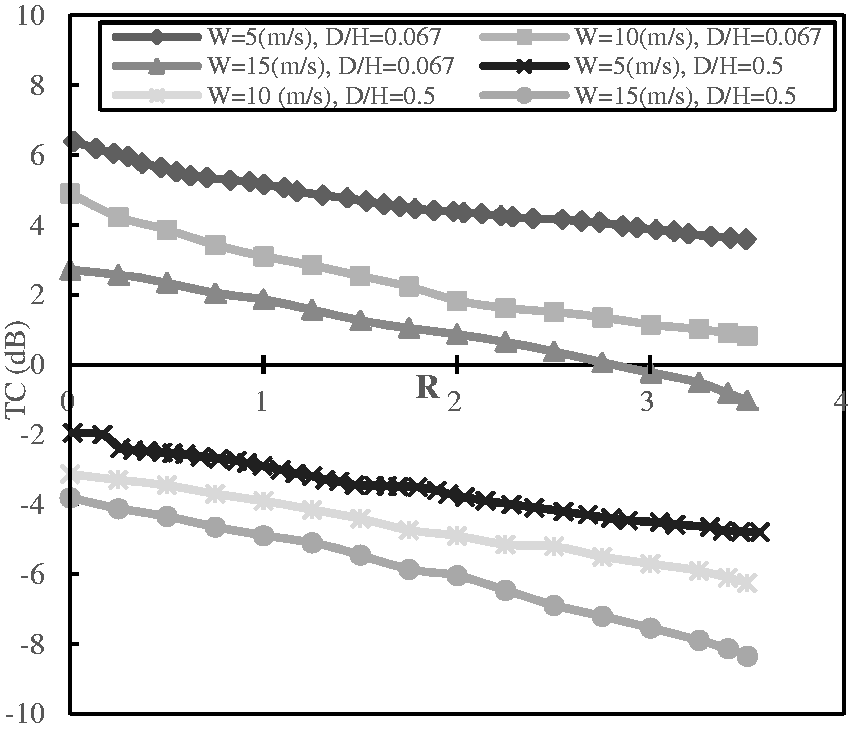
TC variation at the normal incidence and frequency range 50–1000 Hz in three wind speeds 5, 10, and 15 m/s, and D/H ratios 0.067 and 0.5.
Ogden and Erskine36,37 defined a transition regime for sound scattering from the sea surface in which both subsurface bubbles’ population and surface RMS height are involved in the scattering phenomenon. These two mechanisms are involved in transmission of sound from a realistic sea surface. In addition, the wind speed increase causes an increase in both surface RMS height (according to Pierson-Moskwitz 45 empirical relation) and subsurface bubbles’ population, equation (37), which finally result in TC decrease and vice versa. Therefore, it will not be possible to define a separate role for each mechanism in TC variation. However, as mentioned earlier, neglecting the subsurface bubble population effects will result in an underestimation of the TC values.
Figure 16 presents the TC at frequencies 100 Hz, 500 Hz, and 1000 Hz and as shown in Figure 15 for two different D/H ratios 0.067 and 0.5. As shown in Figure 15, in Figure 16, the change in wind speeds in a range of 2–15 m/s at a constant frequency changes the acoustical roughness values, and TC results are studied at a constant frequency and D/H ratio, while the wind speed varies. As evident in Figure 16, by increasing the wind speed, which yields an increase in the subsurface bubble population and RMS wave height at a constant frequency and D/H ratio, the TC values decrease. Also, a frequency increase from 100 Hz to 500 Hz or 1000 Hz has the same effects on TC values and causes its reduction. Since frequency and wind speed, respectively, indirectly determine, through wave number and surface RMS height, the surface acoustical roughness, R, and the wind speed determines subsurface bubbles’ population, one may, based on the results in Figures 15 and 16, conclude that at the normal incidence, the increase in frequency and wind speed causes a reduction in TC values and vice versa. In Figures 15 and 16, TC is investigated at the normal incidence and in a case where receivers are exactly under the source location. However, as mentioned earlier, the angle
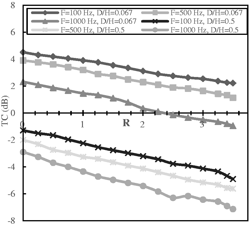
TC variation at the normal incidence and in wind speeds between 2 and 12 m/s at three frequencies 100, 500, and 1000 Hz, and D/H ratios 0.067 and 0.5.
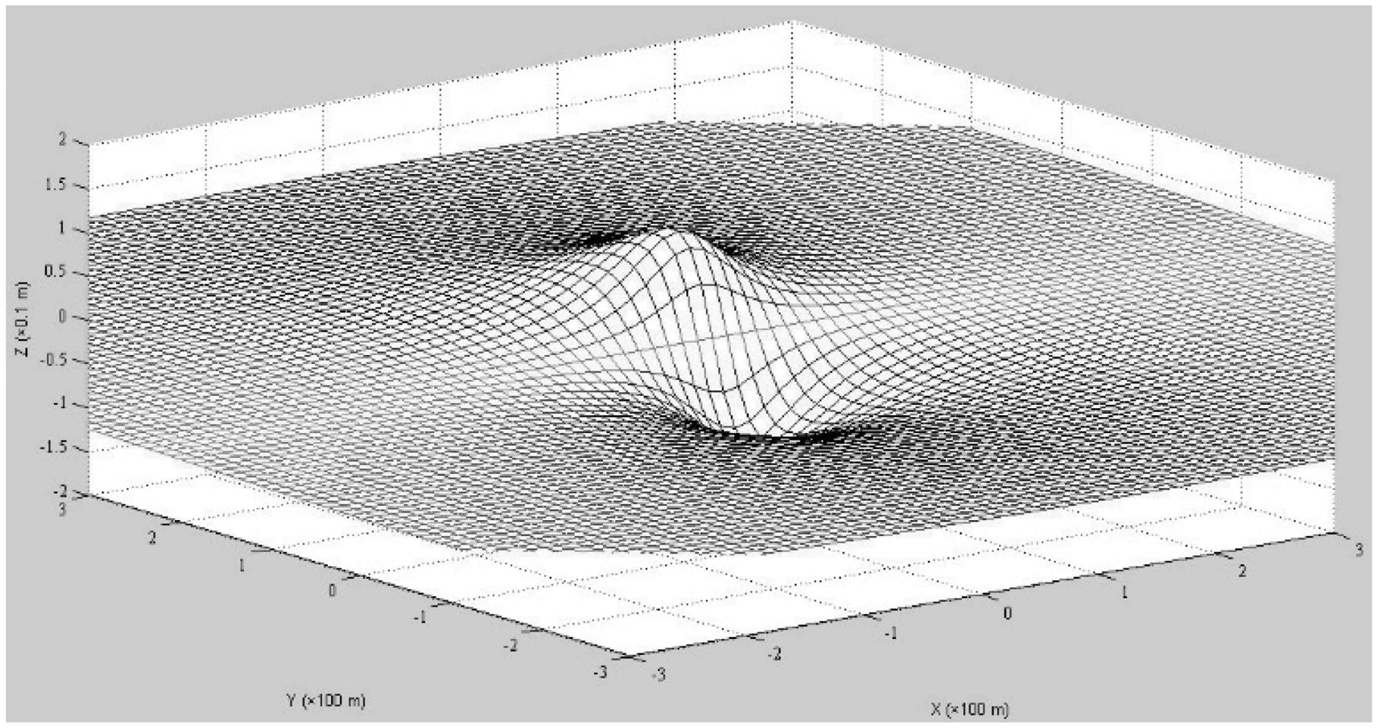
In Figure 17, the results of TC in an underwater field with dimensions
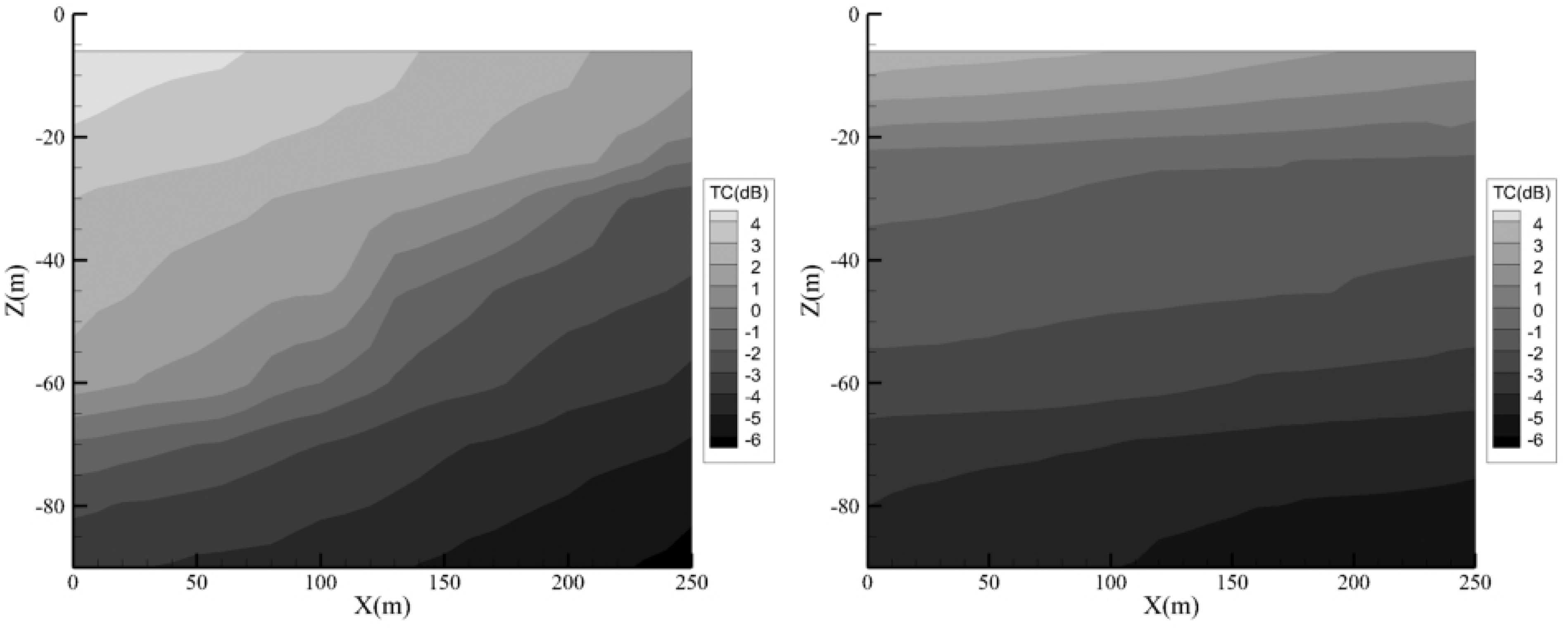
TC underwater, sound source is located at x = 0 and z = 90 m: (a)
Conclusion
In this paper, transmission of low frequency sound generated by a localized point source is investigated in the air through rough bubbly air–water interface. To accomplish this goal, the modified Kirchhoff-Helmholtz integral is applied. In general, two mechanisms of subsurface bubble clouds and surface geometric roughness are involved in sound transmission in a realistic sea surface. In this paper, a modified Kirchhoff-Helmholtz integral is presented in which subsurface bubbles’ population effects are accounted for. The proposed optimization of Kirchhoff-Helmholtz integral is achieved through inserting a transmission coefficient ▪ into the corresponding relation. Therefore, a three-phase region of air, bubbly water, and water at the sea surface region is considered. As a result, sound transmission from air into water passes through middle medium of bubbly water. In the considered air, water, and bubbly water media, a relation is derived for TC based on the transmitted pressure to the water from the point source localized in the air. The relation is studied versus different effective variables such as wind speed W, frequency f, source to receiver positions ratio D/H, and acoustical surface roughness R. Summation of the two components of coherent and incoherent terms forms the final TC relation. At low surface acoustical roughness R≪1, the coherent term of the TC relation is dominant, but at higher acoustical roughness R>1, the incoherent term is dominant. Since the incoherent term is formed by summation of functions of the surface elements, various terms such as element area Ai, transmission coefficient
Due to the presence of the wind-generated subsurface bubble clouds in a realistic sea condition, the propagation of sound in the middle bubbly water medium faces different impedances, compared to the air and water impedances. Therefore, transmission of sound is affected by the features of this medium. In this paper, by including the subsurface bubble clouds’ effects, the underestimation of TC values reported by earlier studies is resolved. Also, the parametric studies of TC versus various variables are conducted for different setups of the numerical simulation presented in the current paper. Based on these studies, it is concluded that at normal incidence, frequency increase at a constant wind speed and vice versa will result in the reduction of TC for a constant D/H ratio. Also, an increase in D/H ratio at a constant surface acoustical roughness R will result in the reduction of TC. However, at a constant D/H ratio, the increase in angle
Footnotes
Declaration of conflicting interests
The author(s) declared no potential conflicts of interest with respect to the research, authorship, and/or publication of this article.
Funding
The author(s) received no financial support for the research, authorship, and/or publication of this article.