
Abstract
In recent years, several solutions for structural vibration control of buildings have been proposed. In particular, the combination of base-isolated structures with complementary variable damping devices has been successful in reducing the base isolator displacements without increasing the building superstructure response when subjected to earthquake loads. In this paper, a magnetorheological device is installed on a 2-DOF mechanical model mounted on an experimental uniaxial shaking table. A simple numerical simulation model is derived for the experimental setup and it represents a typical base-isolated structure with a semi-active vibration controller. The control law combines a force tracking integral action with a clipped on–off adaptation rule that changes the magnetorheological damping in real time. The effectiveness of the proposed solution is demonstrated for both earthquake-like and real earthquake input ground motions. A comparison between the numerical and the experimental results validates the numerical simulations and it gives confidence in using this model for validation and evaluation of other semi-active control solutions based on magnetorheological dampers.
Introduction
Earthquakes are one of the most destructive natural catastrophes in the world with a strong impact on the economy due to their potential for causing loss of human life and infrastructure destruction. The increase in the building concentration that has resulted from the population growth in urban areas has further exacerbated this problem. These concerns have instigated research and development on seismic safety enhancement techniques aimed at civil engineering structures, in order to provide adequate strength and ductility for the dissipation of the dynamic input energy of earthquakes. 1 Conventional design methods for earthquake resistance of building structures allow for some structural damage by accounting for the inelastic deformation capacity of some of its elements. However, this approach could be problematic for critical infrastructures and motion-sensitive equipment that needs to be operational during and after the occurrence of an earthquake event. Therefore, new solutions have been extensively investigated.2–5
In general, a seismic event can be characterized by its amplitude Fourier spectra in a given band of interest. In order to avoid the seismic input action frequency content, base-isolated structures are being adopted as a solution for reducing the transmission of seismic forces and energy to the structure during seismic events. 6 Typical base-isolated structures use elastometric or lead-rubber bearings installed between the base of the structure (superstructure) and the soil foundation (substructure), thus providing a discontinuity surface on the horizontal plane by means of material flexibility and damping. A base-isolated structure becomes more flexible in the horizontal direction since its fundamental frequency is reduced and the capacity for filtering the excitation components close to the fundamental frequency of the structure increases. 7 However, two important aspects have to be taken into account when designing these types of structures: (i) the base isolation system must be well tuned taking into account the expected characteristics of the seismic excitations; (ii) large isolation displacements could occur, especially at near-fault locations where large pulse-like ground motions are generated. 8 To reduce such displacements, supplementary devices are often prescribed but it is found that under these circumstances structural inter-storey drifts and absolute accelerations may increase. 6 Thus, damping systems which can reduce base isolator displacements without increasing superstructure response, for both near- and far-field ground motions, are therefore desirable. 9
This problem has motivated the scientific community to exploit the combination of base-isolated structures with complementary force devices. 6 Recently, semi-active devices have been installed at the base of base-isolated structures aiming at its structural vibration reduction.8–11 A semi-active device is basically an adjustable passive device with a working principle that is similar to a feedback control system. A control law adjusts the mechanical properties of the device in real-time with the goal of minimizing the structural vibration (relative displacement and absolute acceleration) by measuring the applied forces and the structural acceleration responses. Thus, the control forces developed by semi-active devices are dependent on both the adjusted control variable and the structural motion experienced. The recognized main advantages of using semi-active devices are the following: (i) they are dissipative systems with the generated mechanical energy limited by the damper range variation, which makes the whole system (the structure and control device) intrinsically stable from a dynamic point of view; (ii) they generally operate using their own power supply to energize all the components that comprise the electrical circuit (controller, sensors, and device), which make them autonomous and independent of the main power sources that could fail during an earthquake event; (iii) they are especially suited for collocated control implementation due to the facility in developing a compact solution for application in real structures, with the same level of accessible installation as passive solutions. Semi-active devices can use different types of technologies, such as variable stiffness, friction dampers, fluid viscous dampers, electrorheological (ER) dampers and magnetorheological (MR) dampers. An extensive literature review on this subject can be found in various references.2–5,12 The semi-active concept was also successfully applied to a broad class of vehicle vibration isolation problems, ranging from tractors and other farm vehicles, to high-speed ground transportation vehicles.13–15 Semi-active fluid dampers (oil dampers) are still the most common solution today when large forces are needed and have been widely used in civil engineering structures in Japan. 16 Examples are found for instance in the House of Creation and Imagination of Keio University (Yokohama), completed in 2000, 16 and in the 11-storey Keio University building—Mita South Building erected in 2005. 10 The MR solution was applied in the Tokyo's National Museum of Emerging Science and Innovation (Miraikan), where two 30-ton MR fluid dampers have been installed between the third and fifth floors, 17 as well as in several residential buildings. 18 Recent experimental works have demonstrated the effectiveness of MR technology for seismic response mitigation in civil engineering applications when compared with passive solutions.19–23
However, the presence of a semi-active device adds an extra complexity to the structural vibration control system design due to the resulting nonlinear dynamics.8,10 In view of this, a wide range of control strategies and algorithms have been proposed in the literature. Dyke and Spencer 24 and Jansen and Dyke 25 presented a control solution based on the Lyapunov stability theory, bang-bang control, modulated homogeneous friction control, and clipped optimal control. Optimal control-based algorithms are also commonly adopted. 26 More complex algorithms have been proposed based on robust control, 27 fuzzy logic, 19 neural networks, 28 backstepping and quantitative feedback theory techniques, 29 and wavelet transform. 26 Other control design procedures have been incorporated in new structures or retrofitted into existing ones: (i) based on damping reduction factors 30 for linear single-degree-of-freedom models with a semi-active viscous dampers; and, (ii) based on a multi-performance-based control design using a genetic algorithm that extends the single-degree-of-freedom approaches to multi-degrees-of-freedom with a decentralized semi-active control algorithm. 31 Recently, Oliveira et al.32,33 presented a comparative study of several semi-active control strategies for base-isolated buildings. It is shown that the combination of a force tracking integral controller with a variable damping adaptation rule provides a good compromise in reducing both the acceleration and the relative displacements of a base-isolated 10-storey building simulation model when subject to near- and far-field seismic ground motions. One of the major drawbacks when designing structural vibration controllers is the difficulty in carrying experimental testing campaigns under realistic physical situations. This has limited a wide acceptance amongst professional seismic engineers of the majority of the developed structural vibration control algorithms. In order to guarantee that the performance obtained from numerical simulations can be replicated for realistic scenarios, accurate numerical models of the most relevant physical components involved in the real scenario need to be considered at the controller design stage. In this work, a 2-DOF mechanical model representative of a typical base-isolated building excited by one-dimensional earthquake loads is mounted on top of an experimental uniaxial shaking table. This experimental test bed is located at the National Laboratory of Civil Engineering (LNEC). The installation comprises a MR damper installed at the base isolation system level that will modify the system damping in real-time according to a given control law. After obtaining accurate dynamic models of both base-isolated building and the MR device, a structural vibration controller is designed combining a force tracking integral controller (I) with a clipped on-off (COO) MR damping adaptation law. A comparison between the experimental and the numerical simulation results have been performed considering several scenarios of earthquake-like input ground motions applied to the platform representing typical far-field (type 1) and near-field (type 2) seismic actions encountered in Portugal. The input ground motion records from the 1994 Northridge Sylmar earthquake have been also used to validate the behavior of the control scheme. Besides confirming the effectiveness of the proposed semi-active structural vibration controller, this comparative study will help to validate the adoption of the developed numerical simulation model in further semi-active control schemes integrating MR dampers.
Experimental test bed
The uniaxial shaking table, shown in Figure 1, consists of a steel platform that slides over several bearings mounted on the main structure. This platform is able to support models up to six tons with dimensions of 3 × 2 m2. A hydraulic actuator linked between the main structure and the platform is used to input the displacement time histories. The actuator is able to provide 220 kN of force with a maximum 170 mm stroke. A hydraulic oil circuit regulated by a servo-valve operated by a servo-controller is used to power the actuator. One displacement transducer is incorporated in the actuator to measure the platform position and used as the feedback signal in the control loop. This experimental test bed includes the physical model used to reproduce the dynamic behavior of a base-isolated structure with semi-active control: a 2-DOF mechanical model; a semi-active MR device, the sensors and signal conditioners, the data acquisition, and the controller unit. The MR device is operated by the data acquisition and control system using the information provided by the sensors signals (one force transducer, three accelerometers, and three displacement transducers). The reference signal for the shaking table is also defined on the data acquisition and control system.
Uniaxial shaking table experimental installation (left); schematic view (right).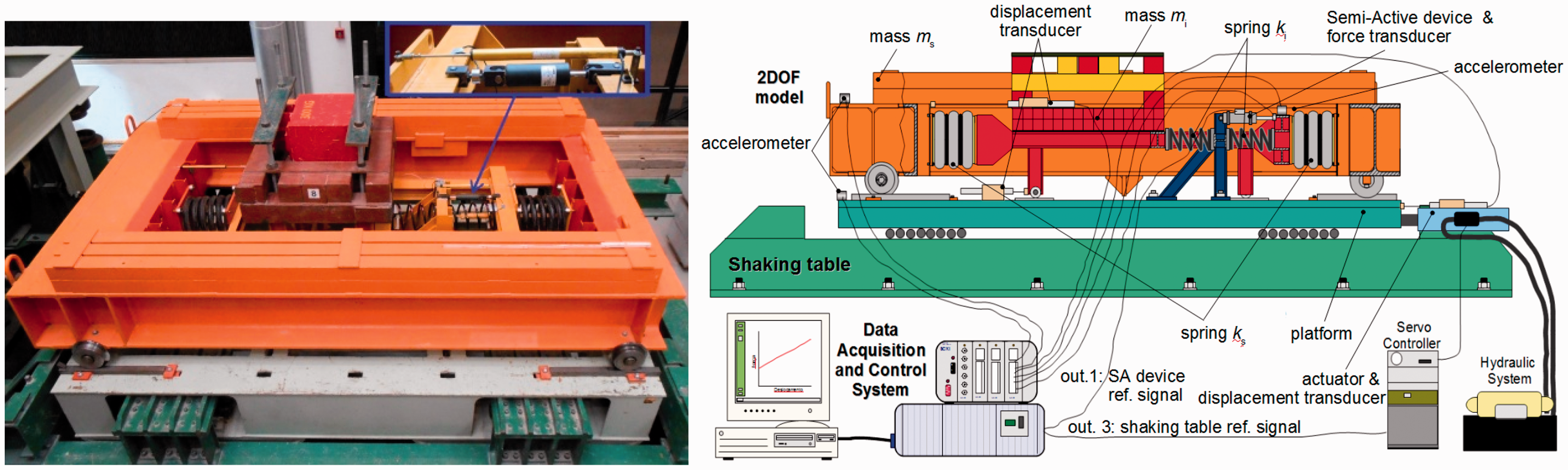
The top platform shown in Figure 1 represents a 2-DOF mechanical model representative of typical base-isolated buildings excited by one dimensional earthquake loads. This 2-DOF model was designed to capture the most significant mechanical behavior of a 10-storey base-isolated structure when subjected to input ground motions as shown in Figure 9. This stems from the fact that most of the energy frequency content of the input ground motions is below 5 Hz and their relevance is felt up to the second mode of vibration of the 10-storey base-isolated structure, as confirmed by the authors previous studies.32,33 A simplified view of the 2-DOF mechanical model is shown in Figure 2.
The 2-DOF model.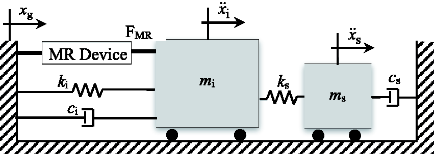
The governing equations of motion of the 2-DOF model can be expressed by the following two dimensional matrix form

The choice of parameters for the 2-DOF model is intended to reproduce the mechanical behavior of a 10-storey base-isolated structure. This is accomplished by matching the first two modal characteristics (frequency and damping ratio) with those from the 10-storey base-isolated structure used in previous studies [32,33] i.e. f1 = 0.39 Hz; ξ1 = 9.34%; f2 = 2.99 Hz; ξ2 = 5.57%. This leads to the following 2-DOF model characteristics:
In order to identify the model characteristics under dynamic response, the physical model was installed on the shaking table without the MR device and subjected to a campaign of tests. A white-noise signal (duration of 360 s passed through a higher pass filter at 0.2 Hz and integrated once) was used as the reference signal for the shaking table (peak values of 22 mm of displacement and 7.1 m/s
2
of acceleration). For the determination of the validity range of the proposed 2-DOF model, a comparison of its frequency response functions (FRFs) with the experimental model was made considering different input scale factors. The experimental tests confirmed that the 2-DOF model is a valid linear approximation of the experimental model for input scale factors from 0.6 to 1. In this range, only a slight increase on the damping ratio is observed at both system resonance frequencies for the experimental model, as seen in Figure 3 (left). However, the same conclusion cannot be drawn for smaller input scale factors, and these would typically correspond to smaller energy input signals, which have a limited impact on the structure vibration. Thus, it is reasonable to conclude that the proposed 2-DOF model is an adequate dynamic model for the most relevant input accelerations that may affect the system.
Frequency response functions (FRFs): experimental FRFs for several input scale factors (0.6 to 1) (left); comparison between the experimental and the regenerated FRFs (right).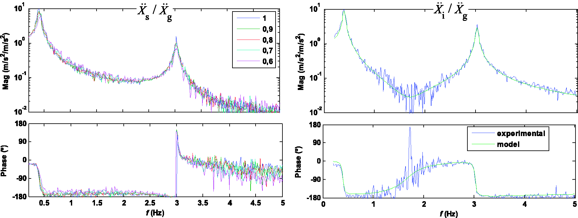
The continuous time model in equation (1) and the experimental model (in terms of FRFs), as shown in Figure 3 (left), were used to identify the system parameters and modal properties. A prediction-error optimization method was considered, assuming the model parameters
The semi-active MR damper
A MR damper model RD-8041-1 with a current controller RD-3002-03 manufactured by LORD Corporation (http://www.lord.com) was used as the semi-active device in this work. The damper has a stroke of 74 mm and can reach up to 1.5 kN at 0.2 m/s for a current in the coils of around 2 A. The current controller uses the pulse width modulation (PWM) technique to control the current in the damper coil using an input voltage as reference. A constant voltage (12 VDC) power supply was used for producing at least 2 A of current depending on the input reference signal (0 to 5 V). To describe the mechanical behavior of the MR damper, the Bingham
34
and Bouc-Wen35,36 models are commonly considered. In this work, a modified version of the Bouc-Wen model
12
was used
Several tests were performed to characterize the MR damper mechanical behavior: (i) static tests at several displacement points to identify the static components of the device; (ii) dynamic tests, under a stationary regime in the whole displacement range, and under a transient regime, to identify the stationary and transient components of the device. The tests were performed on a universal testing machine as illustrated in Figure 4.
MR damper test set-up (left) and MR damper detail (right).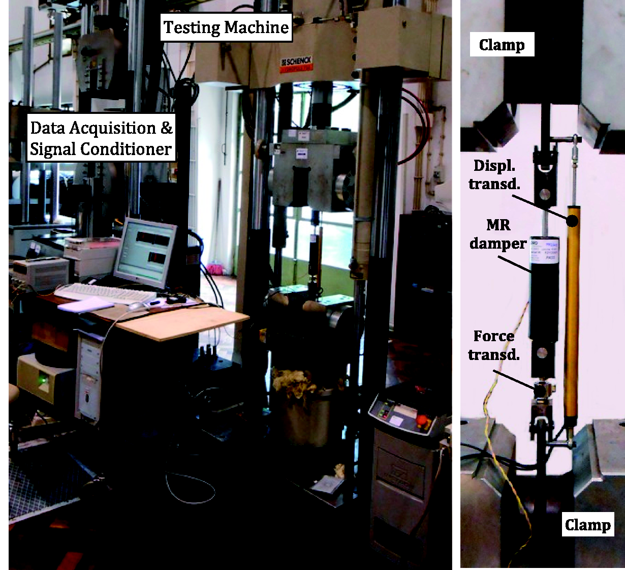
The static test consisted in the application of three displacement cycles (repetition 1, 2, and 3) between –34 mm and 34 mm in steps of 8.5 mm. From the experimental force–displacement data the following values were identified from the model in equation (2), which is simplified to MR damper static test results and adopted mathematical model.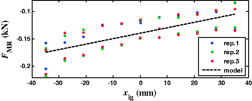
The dynamic tests in the stationary regime ( MR damper response under a sinusoidal input for different input voltages (left). MR damper model parameterization for different peak velocity and input voltage values (right).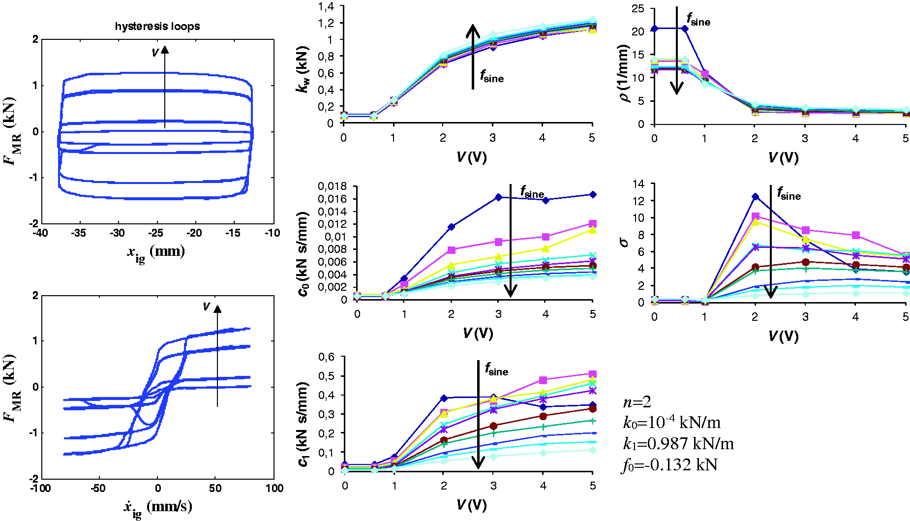
It is observed that several model parameters are dependent on both input voltage and velocity. Thus, for numerical implementation of the model a set of tables relating the model parameters with the input voltage and velocity were defined, whose intermediate values are calculated by linear interpolation.
The dynamic tests under the transient regime used a triangle displacement signal and imposed step voltage to the damper between inversions (12.5 mm of amplitude, frequencies from 0.25 Hz to 0.75 Hz, and input steps from 0 V to 5 V and 5 V to 0 V) to identify the response time of the damper. In order to identify the time constant, the force response at the constant velocity regime to the step input was used. A first-order model Comparison between the measured MR damper force and the force evaluated by the MBW model.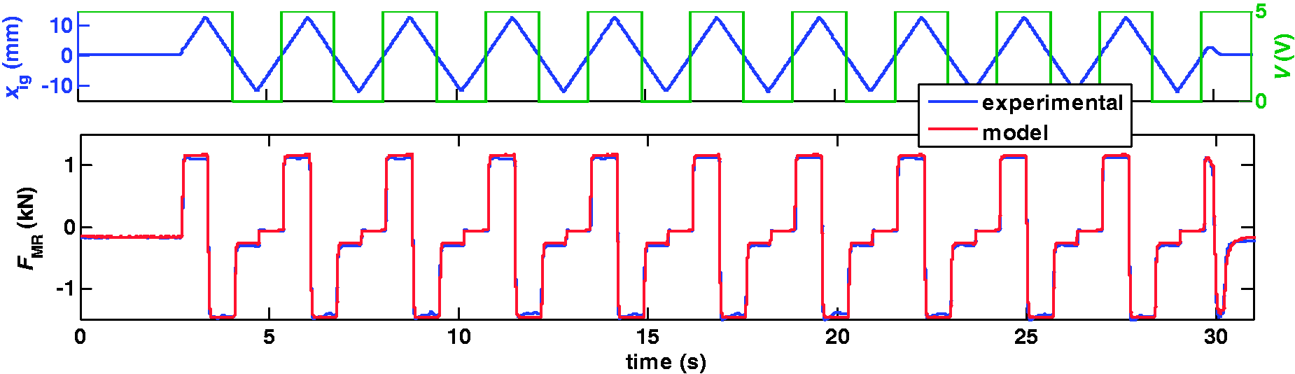
Semi-active vibration control
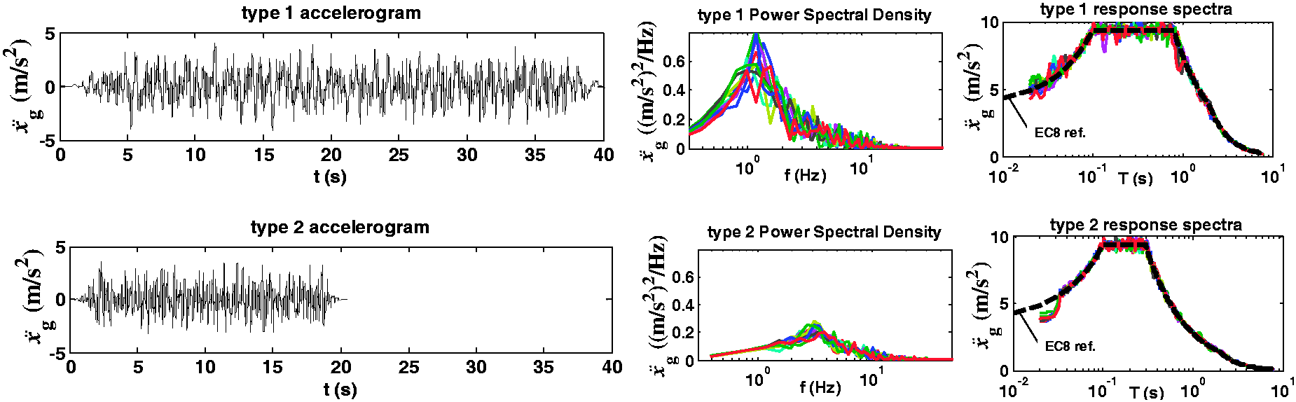
The implementation of the semi-active structural vibration controller using the MR damper comprises one feedback loop with two blocks: (i) a linear integral controller that computes de desired force Block diagram of the semi-active structural vibration controller with a MR damper. Input ground motions considered. Left: example of one artificial accelerogram; Middle: power spectral densities of 10 accelerograms; Right: response spectra of 10 accelerograms.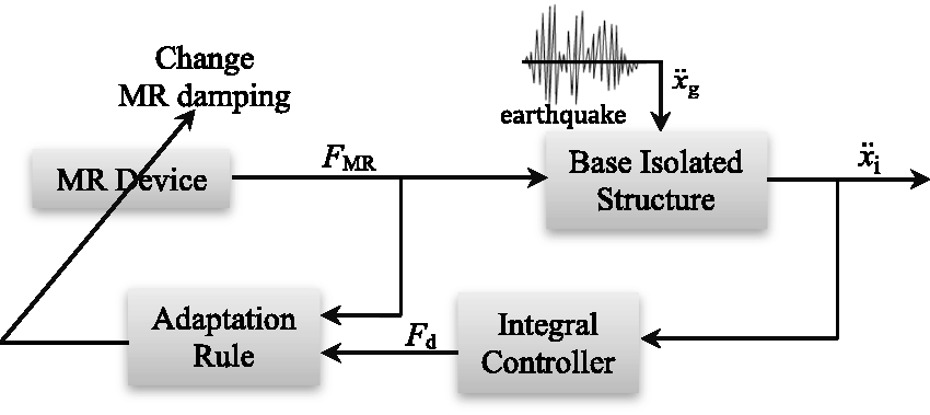
Several control methods are reported in the literature for obtaining the desired optimal force

The optimal integral controller gain

In this work, the integral controller gain KI should be in the range that results by considering 0.4≤ξ≤1 in equation (4), as suggested in the literature.38–40 The selected KI controller gain is the one that results in the lowest average of the 10 peak mass
In an ideal situation, the MR device should be able to produce a force magnitude

Results
An experimental campaign was performed using the 2-DOF mechanical model mounted on the uniaxial shaking table described in the section “Experimental test bed”. Several earthquake-like input ground motions were applied to this platform. Ten accelerograms of a typical far-field (type 1) and near-field (type 2) seismic actions 42 encountered in Portugal were used. The accelerograms and their respective spectrums are presented in Figure 9. It can be seen that type 1 input action has a longer duration and is richer in the lower frequencies (or higher periods) than type 2.
Three physical model configurations are tested: (i) the original structure (2-DOF model only); (ii) the structure with the MR damper in passive mode (under constant input voltage); (iii) the structure with the MR damper in semi-active mode, considering the Integral (I) control law – equation (3) – plus the COO adaptation algorithm – equation (5) – hereafter referred to as ICOO. These experimental results will be further compared with the simulation results obtained from the numerical model of the experimental test bed with the MR device identified in the section “Experimental test bed”.
Before the laboratory experiments were carried out, a preliminary analysis was performed to identify the best passive case and the best controller parameters. The minimum of mean peak mass Numerical and experimental results for Portuguese type 1 and 2 seismic actions, in terms of mean peak values relative to the original structure. Absolute values refer to the original structure.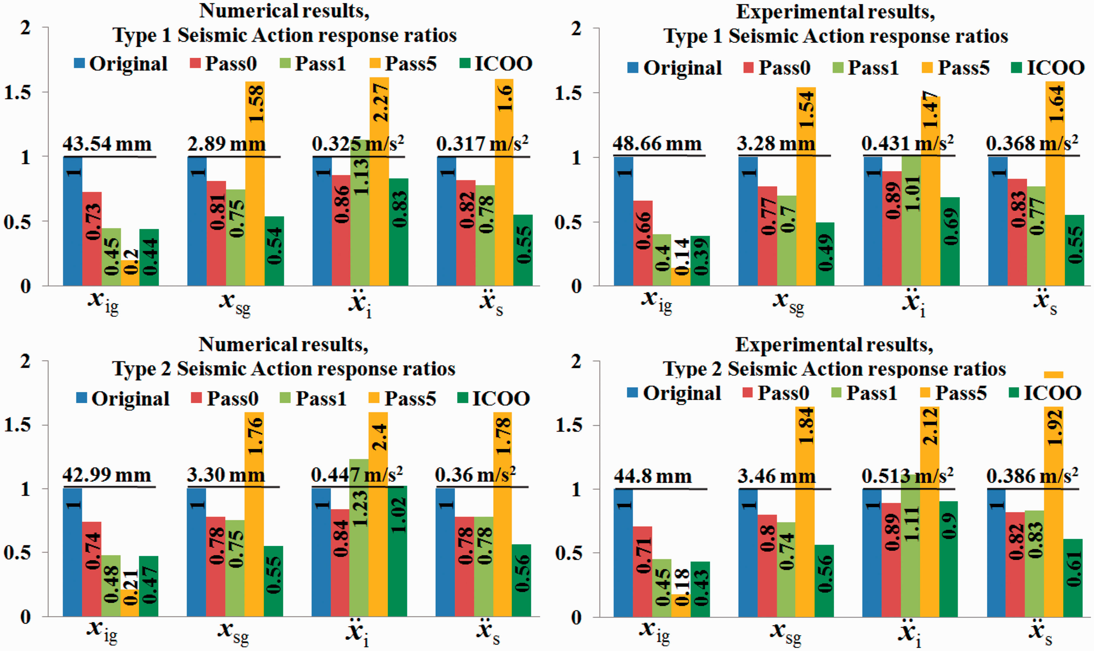
From the experimental results (right graphs of Figure 10) it can be concluded that the passive solution with maximum input voltage, “Pass5”, leads to the highest reductions of the base-isolated to the ground relative displacement but at the expense of increasing the acceleration responses. The best compromise for the passive solution is the “Pass1” case, although an increase in the base-isolated absolute acceleration is observed when compared with the original structure. These results show that the MR damper input voltage needs to be carefully chosen on beforehand if a passive solution is adopted. In contrast, the performance of the semi-active ICOO strategy reveals a good compromise in reducing both the relative displacements and the base-isolated absolute acceleration. For type 1 and type 2 seismic actions, the semi-active ICOO strategy can be considered an effective vibration mitigation control scheme when compared with the “best” passive solution and with the original structure. Despite the normal expected differences between a numerical simulation and the experimental results, similar conclusions can be drawn from the numerical simulation results presented (left graphs of Figure 10). This finding demonstrates the reliability of the numerical model described in the section “Experimental test bed”.
To confirm the effectiveness of the proposed method, numerical and experimental trials were performed based on the 1994 Northridge earthquake (Sylmar station).
43
Figure 11 shows a comparison between the numerical and the experimental results. Scale factors were applied to the records in order to keep the input ground motions in the range of the shaking table displacements and MR damper stroke (7.2% and 8% to FN and FP components, respectively). Similar to the previous results, the ICOO control strategy showed to be an effective vibration mitigation control scheme. Although minimal differences are found between the experimental and numerical results, the same conclusions can be drawn from the numerical model.
Numerical and experimental results for the 1994 Northridge earthquake – Sylmar station, in terms of peak values ratios relative to the original structure. Absolute peak values refer to the original structure.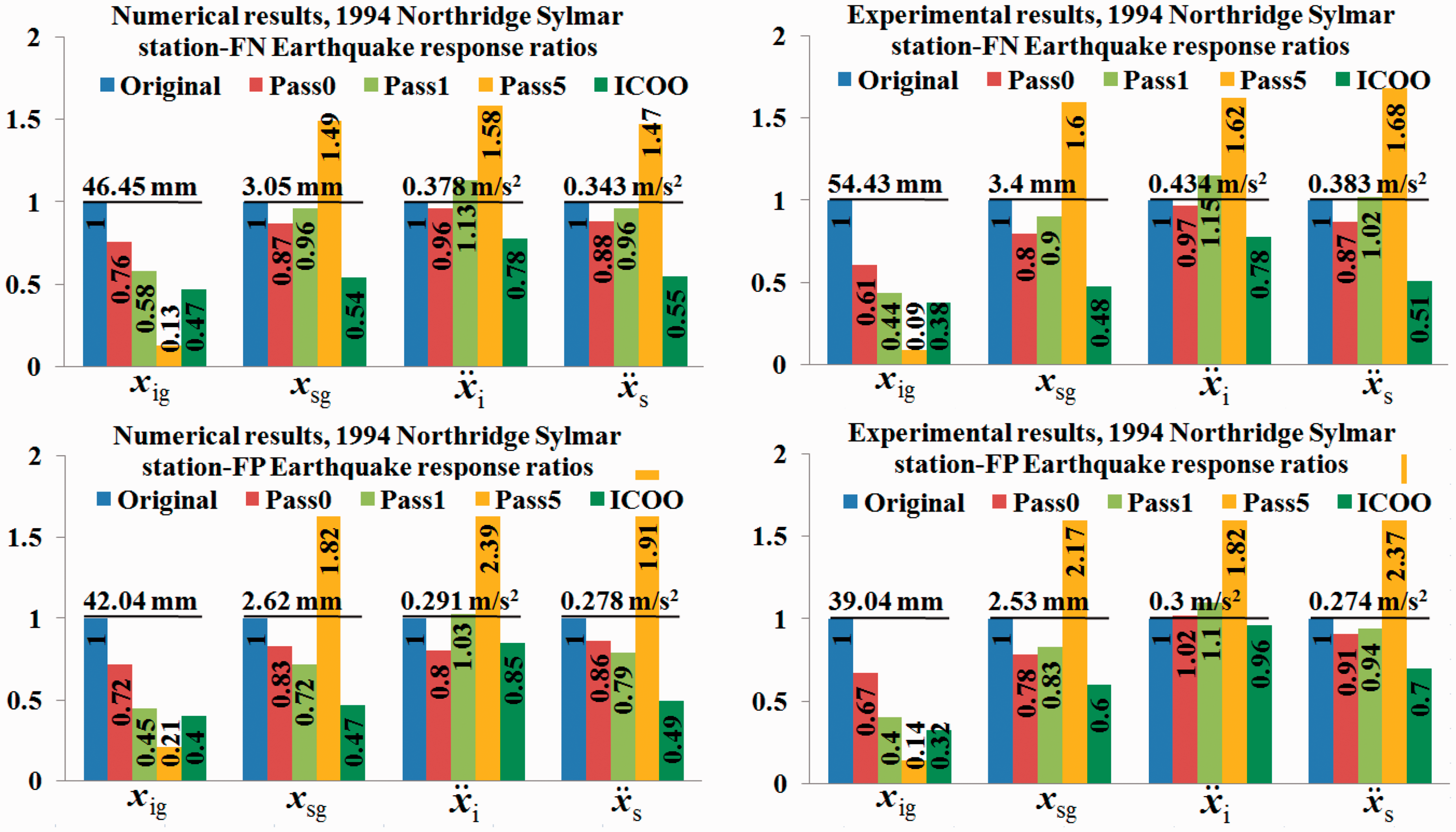
Concluding remarks
This work presents an experimental study on the structural vibration control of base-isolated structures. The experimental test bed simulates a realistic 2-DOF mechanical model of a 10-storey base-isolated structure excited by one-dimensional earthquake-like input ground motions. A MR damper is installed at the base level to reduce the overall structural vibration. The semi-active vibration controller implemented in the current study combines a force tracking integral control action with a COO MR damping adaptation rule. The experimental results demonstrate the effectiveness of this control solution in reducing the relative displacement and the absolute acceleration of the base-isolated structure when compared with passive solutions. A simple numerical model of the experimental test bed was developed. The numerical model was validated and evaluated using the semi-active vibration controller implemented in the experimental setup. The agreement between the numerical model and the experimental results provide confidence on the test bed for validation and evaluation of other semi-active controllers integrating MR dampers.
Footnotes
Acknowledgment
A.S. would like to acknowledge the NSERC Canada Research Chairs program.
Declaration of conflicting interests
The author(s) declared no potential conflicts of interest with respect to the research, authorship, and/or publication of this article.
Funding
The author(s) disclosed receipt of the following financial support for the research, authorship, and/or publication of this article: This work was supported by FCT, through IDMEC, under LAETA Pest-OE/EME/LA0022, and through grant SFRH/BD/84769/2012.