
Abstract
The objective of this paper is to enhance the vibration damping capabilities of magnetorheological (MR) semi-active suspension by utilizing a self-tuning LQG control method. Firstly, to determine the mechanical model of MR damper using the hyperbolic tangent model, mechanical experiments were performed with a damping force test machine under various input excitations. Experimental and simulation data were compared to confirm the accuracy of the mechanical model for MR damper. The MR damper is then incorporated into the vehicle’s semi-active suspension system to create a quarter-car suspension model. In order to tackle the problems associated with low control accuracy and poor dynamic adjustment in traditional LQG controllers where the weighting matrix coefficients are difficult to determine, a self-tuning LQG controller based on gravity search algorithm (GSA-LQG) was designed. Finally, the designed controller performance was evaluated by the simulation and experimental results obtained from the random and sinusoidal excitation roads. Experimental data reveal that when subjected to GSA-LQG control, the suspension control performance is considerably enhanced compared to the passive control, PID control and conventional LQG control suspension. Based on these outcome, it can be concluded that the proposed algorithm is effective and the experimental platform is feasible.
Introduction
Vehicle suspension is a collective term for the mechanism that transmits forces between the wheels and the frame and connects the powertrain between them. The suspension system is created to reduce the shock and trembling produced by bumpy road surfaces and wheel oscillation, resulting in enhanced driving steadiness and comfort for the vehicle occupants. 1 A semi-active suspension system offers better vibration mitigation, faster response, and superior adaptation to varying road conditions than a passive suspension system. In contrast to an active suspension system, a semi-active suspension system can also accomplish vibration reduction performance comparable to that of the former when it is provided that appropriate control strategies are applied. 2 The widely used semi-active suspension system utilizes the magnetorheological (MR) damper as its actuator, which possesses inherent traits of swift responsiveness, low energy consumption, and a damping force that is easily modulated by a magnetic field.3,4
The effectiveness of suspension control in semi-active suspension systems is directly affected by the accuracy of the MR damper model, given that the MR damper serves as the control component. However, the results of the mechanical characteristic experiment unveil the complex nonlinear nature of the MR damper.5,6 The accurate modeling of the MR damper dynamics is complicated due to the interplay of factors such as the magnetic field inside the damper, the amplitude of external excitation frequency, and the motion state of the piston head, which all influence its damping characteristics. 7 Two main categories can be identified when classifying the currently proposed models: parametric model and non-parametric model. 8 The primary approach for simulating the mechanical characteristics of MR dampers using intelligent control involves non-parametric models, including polynomial models, neural network models, and differential equation models.9,10 Nonetheless, the rheological properties of MR fluids are not taken into account by these non-parametric models, leading to a lack of model adaptation. Parametric models replace the mechanical behavior of MR dampers by combining damping elements, elastic elements, mechanical elements, etc. These models have a relatively simple structure, and currently Bingham models, Sigmoid models, and hyperbolic tangent models are widely used in semi-active control equipped with MR dampers.11–13 Kowk et al. developed a mechanical model for MR dampers taken into consideration by the hyperbolic tangent function, mentioned as the hyperbolic tangent mechanical model which is widely used in semi-active control. 14 However, hyperbolic tangent models involve the identification of a large number of parameters. Guo et al. proposed a modified hyperbolic tangent model. The system employs an alternative form of the hyperbolic tangent function while integrating a setup of viscous damping components and elastic elements interconnected in both series and parallel configurations. 15 The mechanical modeling of MR dampers in this paper relies on the hyperbolic tangent model, as it provides an efficient means of generating an inverse model for the damper.
The primary objective of various vehicle suspension control algorithms is to regulate the ideal force output behavior of semi-active actuators. Therefore, the control strategy employed in suspension systems is highly significant, and in-depth research is necessary to further improve their performance. Numerous advanced nonlinear control methods have been investigated to improve the dynamics of uncertain and nonlinear suspension systems, which including skyhook damping control, PID control, adaptive control, and optimal control applications.16–19 Among them, optimal control method is essentially a function extreme value problem for dynamic system performance indicators in the modern control theory. Accurate mathematical models of the controlled system are required to solve optimal control problems. Semi-active suspensions typically use optimal control theory approaches such as model predictive control theory, linear quadratic gaussian (LQG) theory, and linear quadratic regulator (LQR) theory. Unger et al. introduced a controller and observer framework for a linear quadratic (LQ) based semi-active full-car model. Real vehicle experiments were carried out to demonstrate the remarkable enhancement in ride comfort and road holding across varying vehicle masses. 20 Lu et al. presented a combined control strategy that incorporates both LQR and Skyhook techniques for semi-active vehicle suspension systems. The approach was shown to be effective in controlling the suspension and can be readily implemented on an automotive-grade microcontroller. 21 Chen et al. developed an active suspension system with an LQG controller based on a 6-DOF vehicle model to enhance vehicle roll safety during high-speed steering. The LQG controller weights were determined using analytic hierarchy process and normalization methods. 22 Zhu et al. demonstrated a LQG controller for a semi-active dual-chamber hydro-pneumatic inerter-based suspension system. By comparing it with a conventional semi-active hydro-pneumatic suspension system, showing its ability to account for the system nonlinear characteristics. 23
The aim of optimal control design is to determine the control input that minimizes a specific performance criterion of the system, subject to constraints imposed by the system state equation and other boundary conditions. The control objective for vehicle suspension systems is to minimize tire displacement, body acceleration, and suspension travel. The control effect of the suspension in LQG control is directly influenced by the weighted matrix coefficients used, yet in real-world applications, it might be challenging to find the weighted matrix coefficients. Heuristic optimization algorithms, including bat algorithms, genetic algorithms, and particle swarm optimization, are often employed to update matrix coefficients for optimal control, improving the efficiency of solving optimal control problems.24–26 However, the problem of long optimization iteration time still exists. Additionally, to tune the LQR or LQG control coefficient of car suspensions, fuzzy theory and neural network methods have been used, showing outstanding convergence vibration attenuation effects.27,28 However, they need to be prior established by summarizing various control laws and experiences from a large number of experiments. Related research shows that the gravitational search algorithm has good convergence efficiency and solution accuracy, and has shown successful applications in a variety of optimization problems. 29 This paper utilizes the gravitational search algorithm to optimize the LQG weighted coefficients, where the suspension performance indicators are served as the objective function.
In this paper, we investigate the simulation and experimental demonstration of a self-tuning LQG control method for a semi-active suspension system using MR dampers. With the aim of addressing the issue of low control accuracy and the difficulty of determining weighting matrix coefficients, an enhanced LQG controller known as the gravitational search algorithm-based LQG (GSA-LQG) controller is introduced. The hyperbolic tangent model is employed to construct the mechanical model of the MR damper within the semi-active suspension system. Second, the GSA-LQG controller for the semi-active suspension system was designed using a quarter-car suspension model. Ultimately, simulation validation is employed to confirm the performance of the proposed control algorithm. To enhance credibility, a vehicle suspension test platform is built to conduct experimental verification of the passive control, PID control, LQG control, and GSA-LQG control algorithms.
1/4 vehicle semi-active suspension model based on MR damper
1/4 vehicle model for a semi-active suspension system
The semi-active suspension system is a model that replaces the passive suspension damping unit with a MR damper, which implements a control strategy to govern the controllability of the damping force. In Figure 1, the model of a quarter-car model for an MR semi-active suspension system is displayed. The quarter-car model of MR semi-active suspension.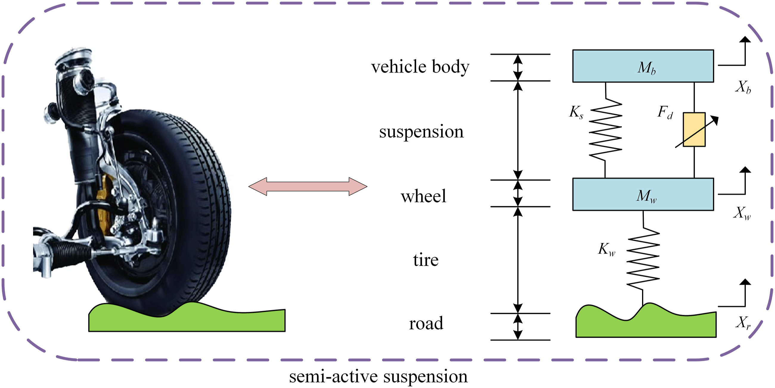
In accordance with Newton second law, the equation of motion for the model is as follows

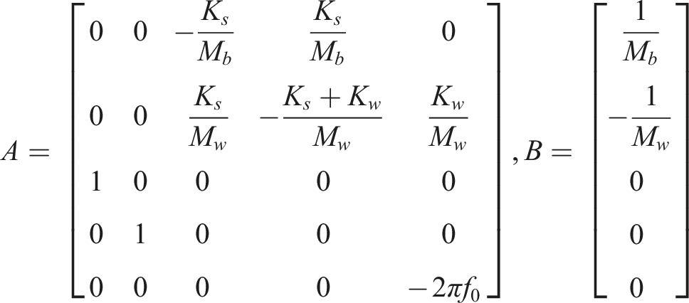
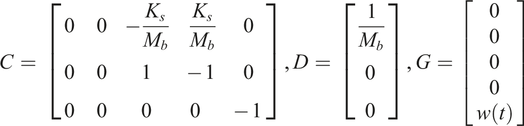
The equation is converted to a state space representation

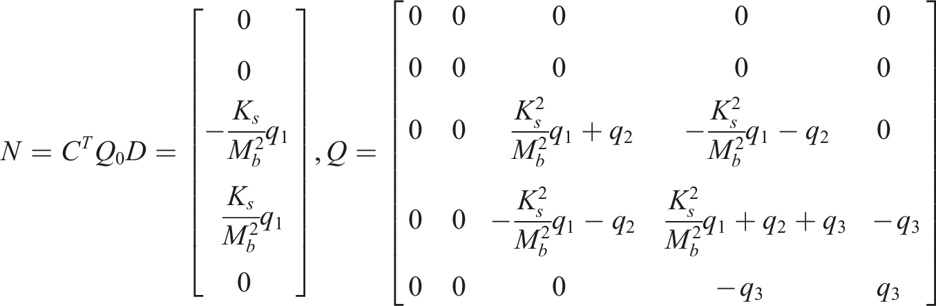
Given that the tire displacement, vertical acceleration of the vehicle, and suspension dynamic deflection serve as fundamental performance metrics for evaluating the vehicle, the system state vector matrix and output vector matrix are defined as follows


Mechanical model of the MR damper
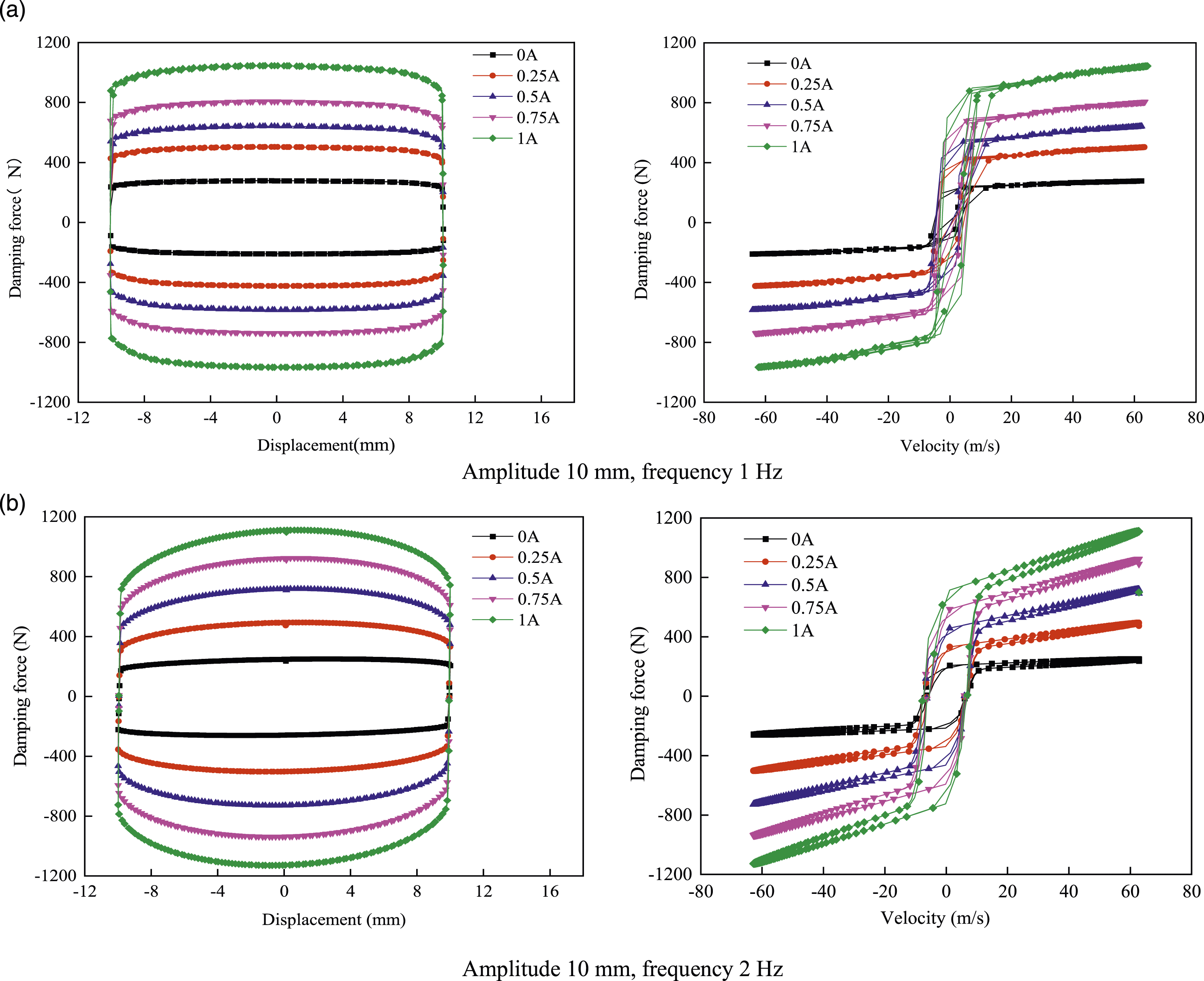
Our research group is responsible for manufacturing the MR damper featured in this article, which is characterized as a single piston rod equipped shear valve mode damper. To test its damping performance, the working conditions under different current and displacement inputs are set. The testing method for MR dampers refers to the Chinese automotive industry standard QC/T 545, which is called the bench test method for automotive cylindrical shock absorbers. As depicted in Figure 2, the experiment utilized sinusoidal stimulation with intensities of 10 mm, 7.5 mm and 5 mm, along with frequencies of 1 Hz and 2 Hz. The DC regulated power supply inputted a DC current of 0 A, 0.25 A, 0.5 A, 0.75 A, and 1 A to the MR damper under different conditions. By analyzing the data saved on the computer, the numerical values of damping force, velocity, and displacement under different working conditions can be obtained. Figure 3 shows the force-displacement curve and force-velocity curve of the MR damper with an amplitude of 10 mm. As shown in Figure 3, the mechanical response of the MR damper demonstrates noticeable nonlinear and hysteresis characteristics. Vibration test system of a MR damper. (1) MR damper (2) Experimental platform (3) DC stabilized power supply (4) Electro-hydrulic servo controller (5) The computer. Mechanical characteristic curve of MR damper.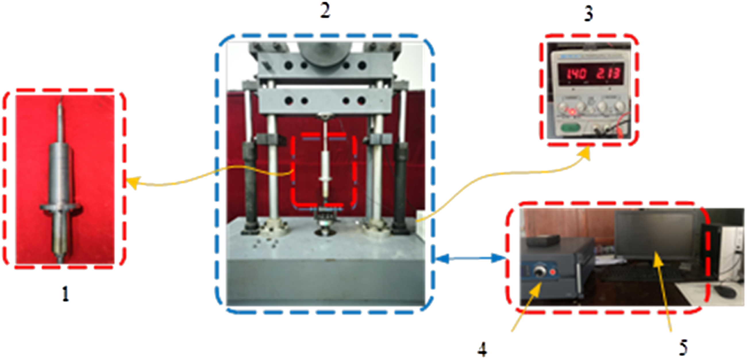
In the practical application of vehicle suspension, it is necessary to carry out accurate dynamic modeling of MR damper. The purpose is to establish dependable control strategy in the simulation analysis by using the established mechanical model. The hyperbolic tangent model accurately represents the nonlinear hysteresis behavior displayed by the MR damper. Meanwhile, the model characterized by its simplistic structure and minimal parameter count making it easier to identify. The improved hyperbolic tangent model provides a comprehensive description of the damping characteristics of MR dampers. In contrast to the hyperbolic tangent model, it considers both the damping characteristics in the high-speed range and the nonlinear hysteresis characteristics in the low-speed range when the MR damper operates under various conditions. The model also reduces the number of parameters to five, and its mathematical expression is as follows

The parameters of the model are determined using the genetic algorithm. The global optimal solution is determined by reducing the fitness function, which is defined as the mean square deviation between the simulated and actual damping forces. The selection, crossover, and mutation processes are utilized to accomplish the identification of the parameters. The definition of the fitness function for the improved improved tangent model is defined as follows


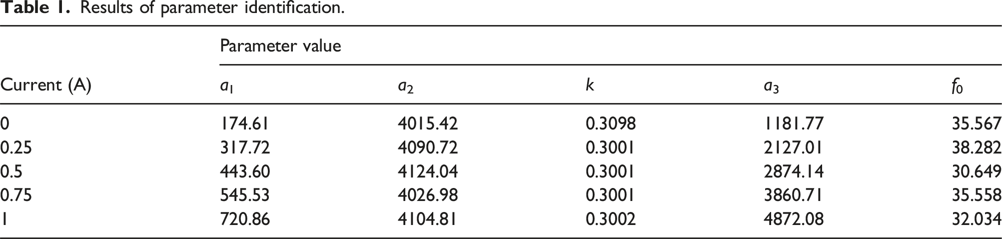
The parameter identification process involved utilizing experimental data generated by a 1 Hz sinusoidal excitation signal with a 10 mm amplitude. Current values are varied from 0 A to 1 A in increments of 0.25 A. The identification process used an initial population size of 200 with real encoding and a uniform random distribution algorithm. The crossover technique applied in this study is the dispersal crossover method, with a probability of 0.8, while the mutation process involves generating random numbers that follow a Gaussian distribution, and its probability is 0.2. The maximum number of iterations for genetic algorithms is limited to 100.
In the improved hyperbolic tangent model, all parameters are restricted to positive values, and their value ranges can be roughly determined through multiple experiments. To achieve an improved fitting effect, the upper and lower bounds Umax and Umin of each parameter are defined as follows


Results of parameter identification.
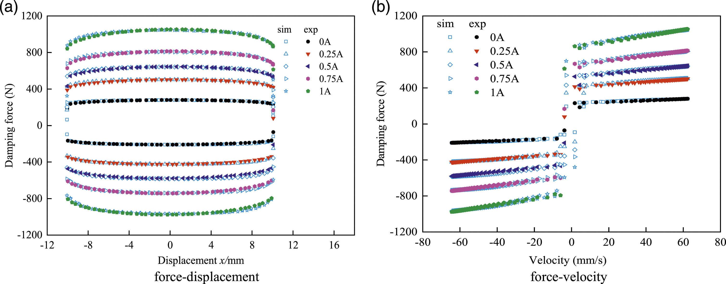
Comparison of simulation results and experimental data.
Design of GSA-LQG controller for MR semi-active suspension system
Design of LQG controller
Conventional LQG optimum control is a control method that expands upon the LQR optimal control by taking into consideration system measurement noise and integrates the Kalman filter. The primary goal of the LQG controller is to reduce the vertical acceleration of the vehicle body, tire deflection, and dynamic deflection of the suspension. Hence, the performance index function is formulated in the following manner. The function to evaluate performance is defined as follows
Represent the performance index function J in terms of the state equation as
The Riccati equation representation is employed to derive the optimal control feedback gain matrix, expressed as t

To directly calculate the LQG control matrix, calling the optimal controller design function in MATLAB software can obtain as
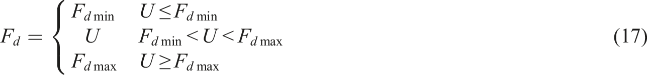
Equations (11) to (15) above represent the optimal control results under unconstrained states. The MR damper plays a crucial role in generating the optimal control force for a semi-active suspension system, and damping force Fd should be between the least value Fdmin and the greatest value Fdmax. As a semi-active actuator, the MR damper can only consume vibrational energy rather than do positive work on the system. When the computed optimal control force is in the same direction as the suspension velocity, the MR damper’s controlled damping force can be used directly as the optimal control force.
30
In contrast, if the optimum control force is oriented in the opposite direction as the suspension velocity, the damping force will appear as Fd = 0. The constraints of Fd are set as
Design of GSA-LQG controller
The weighting matrix coefficients of the output control force is greatly influenced by q1, q2, and q3. In this study, the gravitational search algorithm is used to optimize the weighted matrix coefficients. The gravitational search algorithm is a swarm-based optimization technique that introduces the law of universal gravitation. According to relevant studies, it has been demonstrated that the gravitational search algorithm exhibits superior convergence efficiency and solution accuracy in comparison to particle swarm optimization and genetic algorithm.
Overall performance optimization in the semi-active suspension system is accomplished by normalizing the three performance indicators. The definition of the fitness function L in the gravitational search algorithm is presented as follows
For the GSA-LQG-controlled semi-active suspension, the fitness function must adhere to the condition that the RMS values of its performance indices are lower than those of the passive suspension.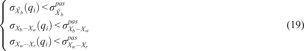
The GSA-LQG controller assigns the generated particle individuals to the suspension weighting matrix coefficients, and judges whether it satisfies the termination condition through the fitness function output by the updated control feedback gain matrix. This process continuously updates the particle positions and velocities through the gravitational search algorithm until the termination condition is met. Particle i represents an object is characterized by a position vector consisting of coefficients from the suspension weighting matrix within a D-dimensional search space. The position of particle i is defined by its vector representation.
Calculating the mass of particle i in the current population based on its fitness function.


The gravitational force exerted on particle i by particle j can be defined according to the expression of universal gravitation as

Particles within the population will attract each other and move towards particles with larger mass. The velocity and position of particle i will be updated in each iteration according to the following procedure
At last, Figure 5 displays the design process of the GSA-LQG controller. Figure 5(a) shows the optimization process of GSA-LQG algorithm. According to the principle of GSA algorithm, this algorithm is used to search and optimize the weighted matrix coefficients of LQG controller. The GSA-LQG controller assigns the generated particle individual to the suspension weighting matrix coefficient, outputs the optimal control feedback gain matrix, and determines whether the termination condition is met through the fitness function. If it is not met, the position and velocity of the particle are updated through the gravity search algorithm until the condition is met. Figure 5(b) shows the GSA-LQG algorithm implementation. The controller is divided into three parts, including MR damper control, semi-active suspension system, and GSA-LQG controller. Under the action of road excitation, the body vertical acceleration, suspension dynamic travel and other signals are transmitted to the GSA-LQG controller, and the controller optimizes and processes the relevant signals to obtain the desired control force. In the MR damper controller, the desired control force is transformed into a control current by the inverse model. The current acts on the MR damper to output the actual damping force, and finally meets the closed-loop control, realizing the desired control tracking of the vehicle semi-active suspension system. Design process of GSA-LQG controller.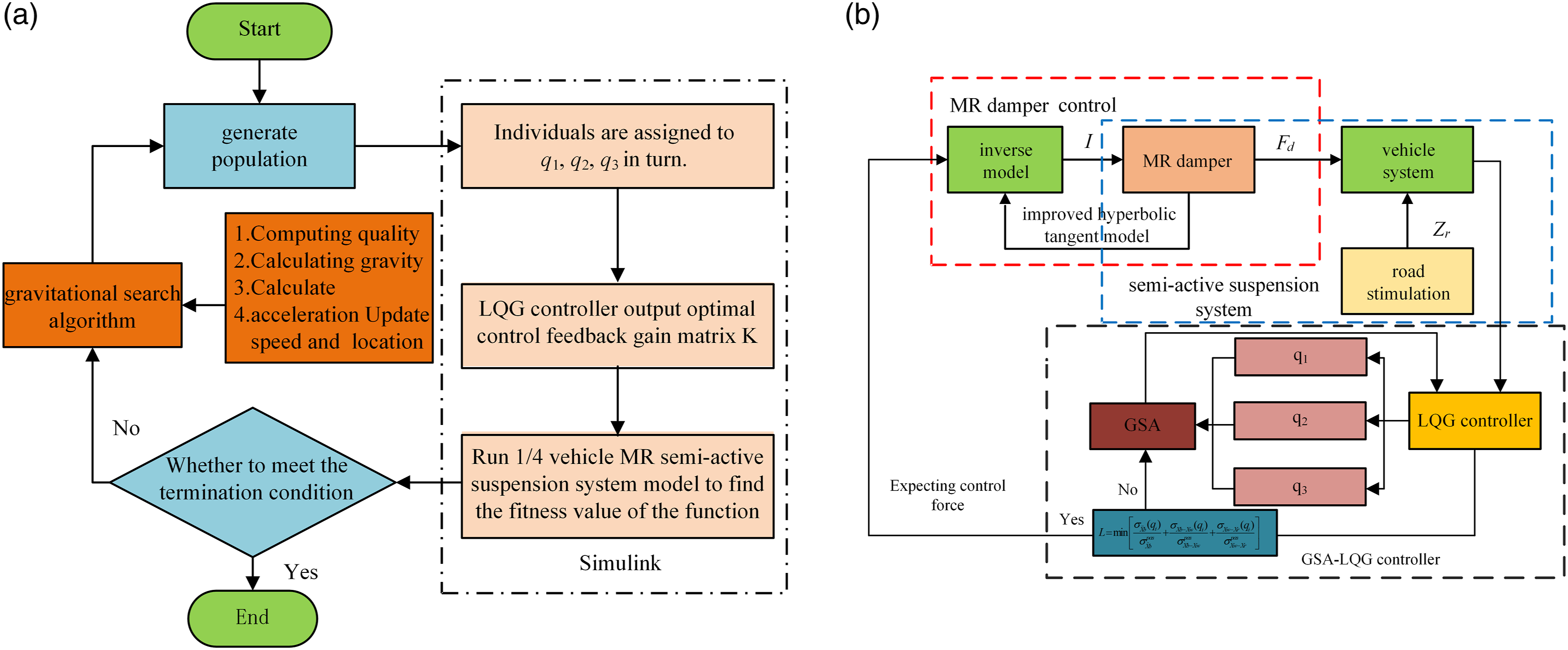
Simulation and experimental validation
Simulation results
When using the gravitational search method to optimize the performance of the LQG controller, a larger population size increases the likelihood of discovering the global optimal solution, but also leads to longer computational time. To fully consider both the response speed and optimization duration, the population size is set to N = 500. In multiple experiments, it is found that the fitness function tends to approach the optimal solution at the 10th iteration, to ensure efficient computation, a maximum iteration limit of T = 20 is defined. The selection of the weighting matrix coefficients depends on the designer’s preferences for suspension performance, and taking into account the overall performance and uncertain factors of the suspension. Additionally, to achieve the desired solution accuracy, the search range for q1, q2, and q3 is expanded to [0.1, 106]. The values of G0 and α for the universal gravitational coefficients and the downforce coefficient are constants, usually taken as G0 = 5 and α = 20.
According to the simulation results, the change of the individual optimal value of the GSA-LQG control fitness function with iteration number is shown in Figure 6. As the iteration times increase, the individual optimal value of fitness function decreases continuously, and reaching its minimum value in the 10th iteration, which shows that the optimization method is effective and has a good convergence speed. At this time, the corresponding weighted matrix coefficients are q1 = 0.9751, q2 = 6.5124, q
3
= 4.2305, which illustrates the efficacy of the optimization approach. Evolutionary process of the GSA-LQG controller.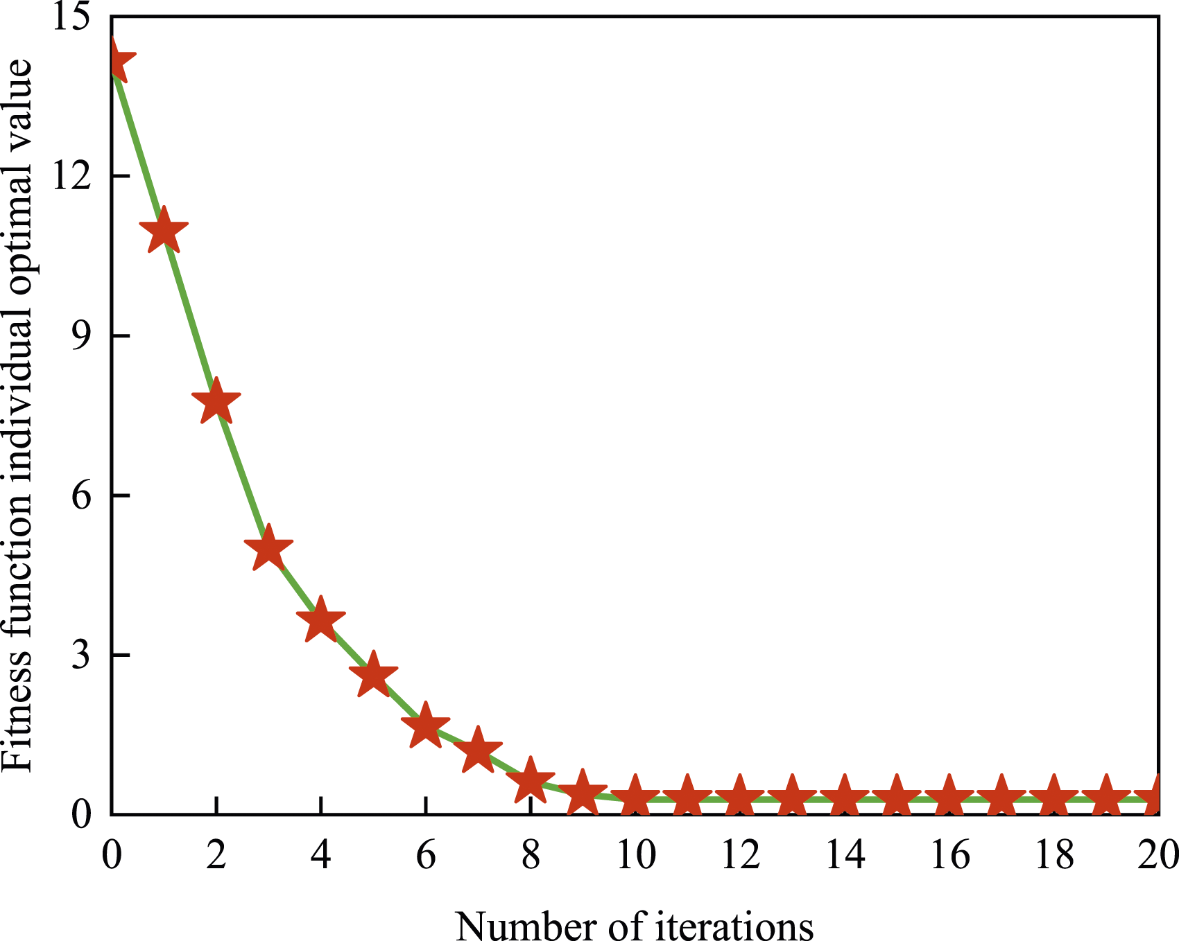
To validate the efficacy of the GSA-LQG control algorithm in improving suspension vibration reduction performance and to demonstrate the rationale for using the gravitational search algorithm to optimize the weighting matrix coefficients in LQG control, simulation results for passive and semi-active suspension systems subjected to impact road and random road excitations are performed, and PID control, LQG control and GSA-LQG control strategies are used. The suspension ability to reduce vibrations is evaluated by examining the tire displacement, suspension dynamic deflection, and vertical acceleration of the vehicle.
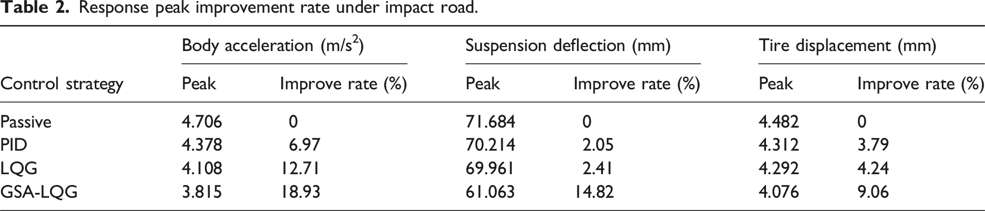
Figure 7 demonstrates the vibration effect of the GSA-LQG control algorithm on an impact road excitation. The impact road with approximately one second input is given in Figure 7(a), and Figure 7(b)–(d) display the simulation outcomes of the passive suspension and MR semi-active suspension when employing the PID control, GSA-LQG control and LQG control under impact road conditions. The curves depicted in the results indicate that the implementation of GSA-LQG control in the semi-active suspension leads to a notable decrease in peak response when compared to the passive suspension, and its vibration suppression effect also shows a decrease compared to conventional LQG control. Table 2 shows the peak values and improvement rates for suspension performance. Compared with the passive suspension, the PID control improved the suspension performance by 6.97%, 2.05%, and 3.79%, respectively. The LQG control improved the suspension performance by 12.71%, 2.41%, and 4.24%, respectively. The GSA-LQG control improved the suspension performance by 18.93%, 14.82%, and 9.06%, respectively. The GSA-LQG control further optimized 6.22%, 10.41%, and 4.82% over the LQG control. Therefore, the semi-active suspension system with GSA-LQG control is capable of reducing the impact of road shock, and improving the smoothness and comfort of the vehicle. Simulation results under impact road excitation. Response peak improvement rate under impact road.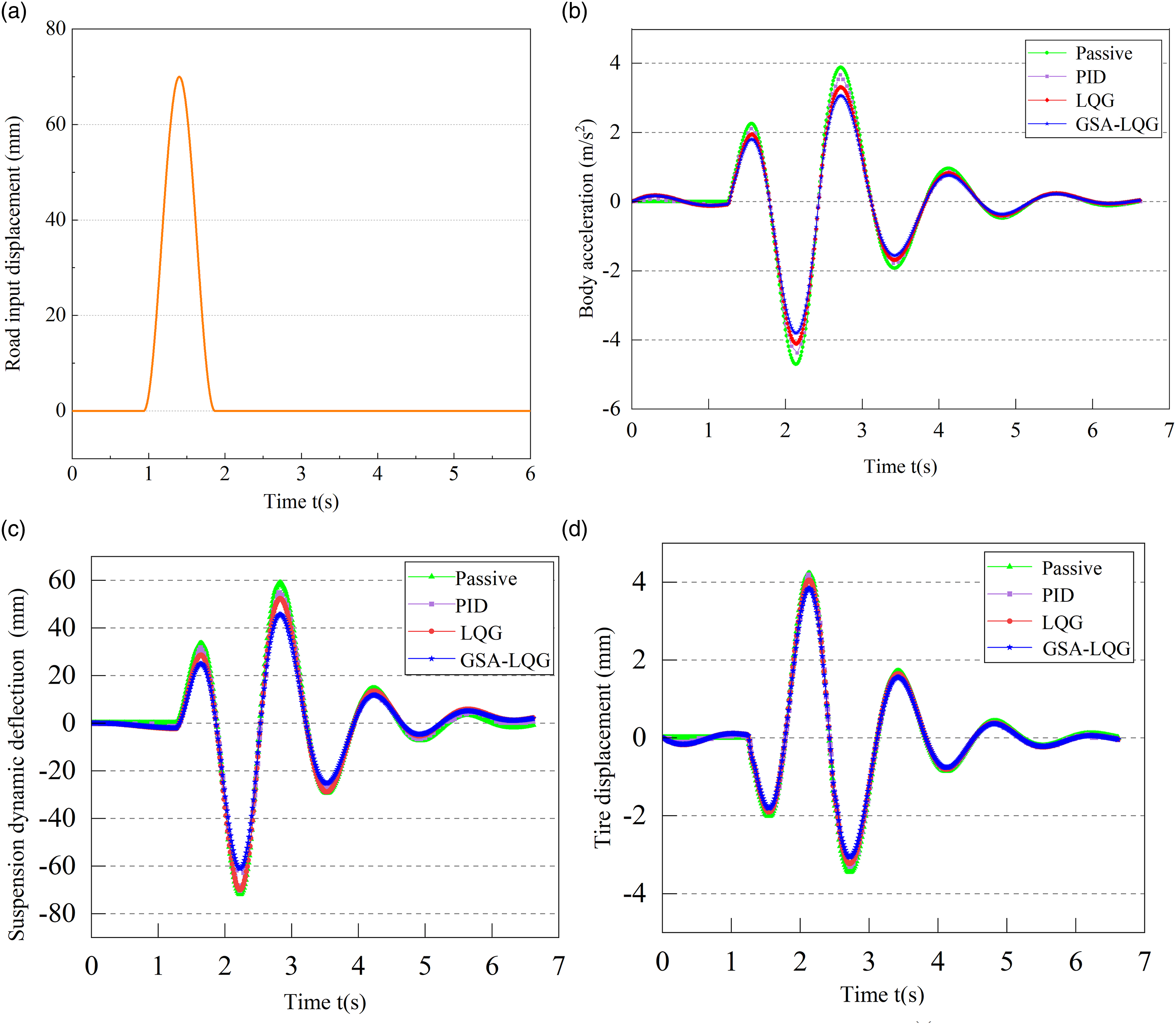
To validate the efficacy of the GSA-LQG control algorithm on irregular road surfaces, simulation results are conducted on the MR semi-active suspension system using GSA-LQG control at a C-class random road with a velocity of 72 km/h. The road power spectral density is mainly used to describe the random road input in vehicle vibration, and the time-domain simulation model of the random road can be obtained by setting the power spectrum. The power spectral density of C-class road is 256 × 10−6 m3.
7
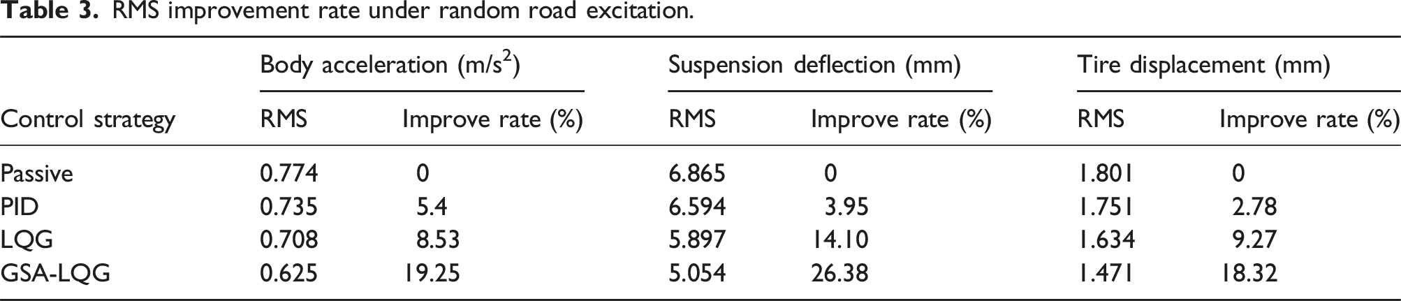
Figure 8 displays the time-domain simulation curves of the MR semi-active suspension system for GSA-LQG control strategies, while the passive suspension and the MR semi-active suspension with PID control and LQG control are used as comparisons. Figure 8(a) show the random road input displacement, Figure 8(b)–(d) show the vehicle’s body acceleration, suspension dynamic deflection, and tire displacement. From the obtained results, the controlled semi-active suspensions exhibit superior performance in reducing vibrations when compared to the uncontrolled passive suspension. Furthermore, among the different controllers, the GSA-LQG controller showcases superior vibration attenuation performance for semi-active suspensions. Table 3 presents the computed RMS values of various performance indicators for the suspension system under four distinct control approaches. The results represent the RMS values of the three performance indicators for the MR semi-active suspension controlled by the GSA-LQG strategy are lower than those for the LQG-controlled and passive suspensions. In comparison to the passive control, the PID control reduces the three indices by 5.4%, 3.95%, and 2.78%, respectively. The LQG control reduces the three indices by 8.53%, 14.1%, and 9.27%, respectively, while the GSA-LQG control reduces them by 19.25%, 26.38%, and 18.32%, respectively. As a result, it can be concluded that the application of GSA-LQG control is effective in improving ride comfort and vehicle handling stability. Simulation results under random road surface. RMS improvement rate under random road excitation.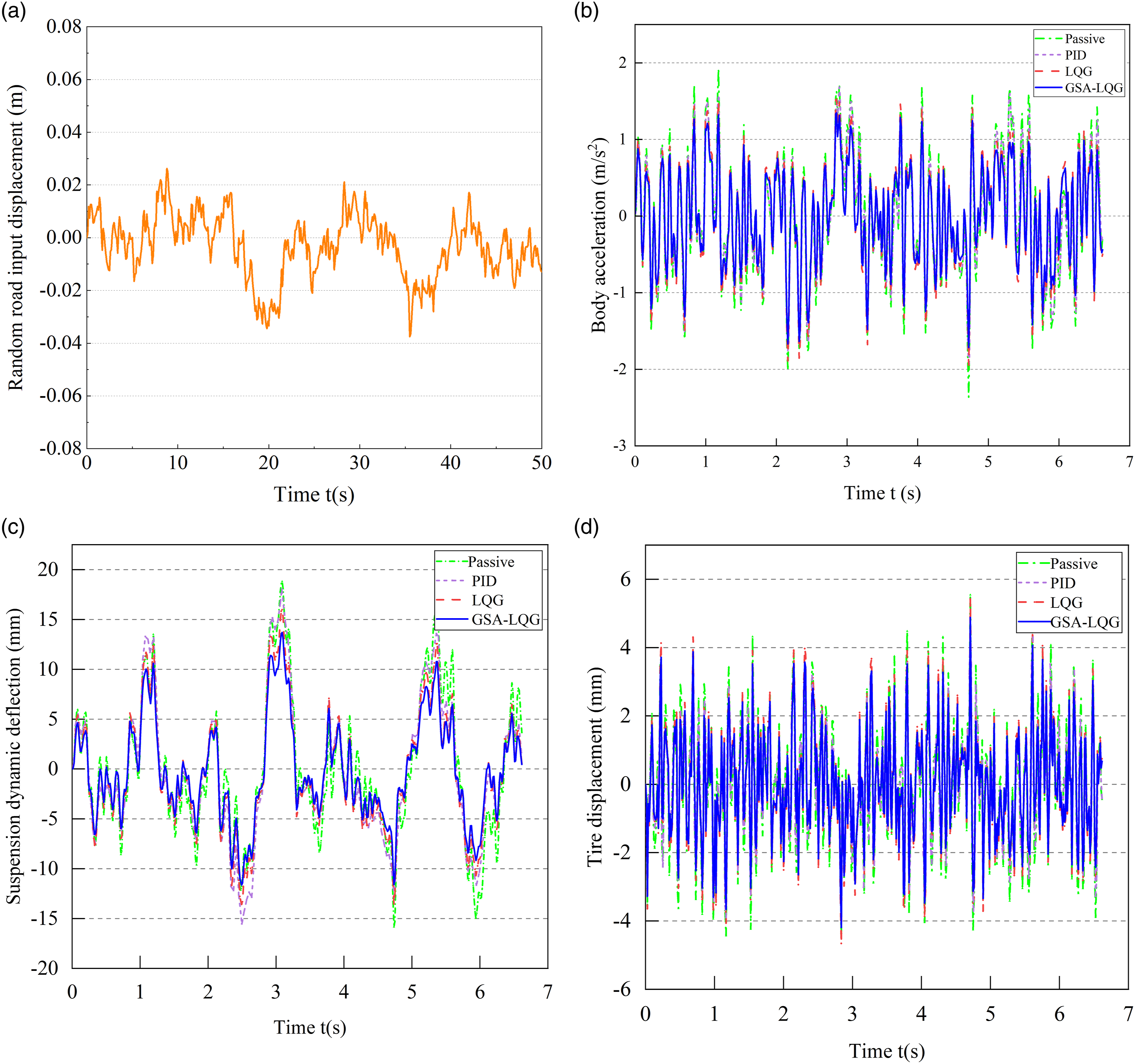
According to the time-domain curve in Figure 8, the frequency domain analysis of the MR semi-active suspension system controlled by GSA-LQG algorithm is further carried out, as shown in Figure 9. In the low-frequency range, the frequency response of the body acceleration, suspension dynamic deflection, and tire displacement controlled by the GSA-LQG algorithm has been significantly reduced. In the high-frequency range, the dynamic response of the suspension system varies within a relatively small range. The frequency response of the suspension performance indicators for GSA-LQG controller almost coincides with the passive control and LQG control. Therefore, the suspension performance of the proposed controller has been effectively improved within the operating frequency range, which further verifies the superiority of the proposed algorithm in frequency domain response. Frequency domain response of random road.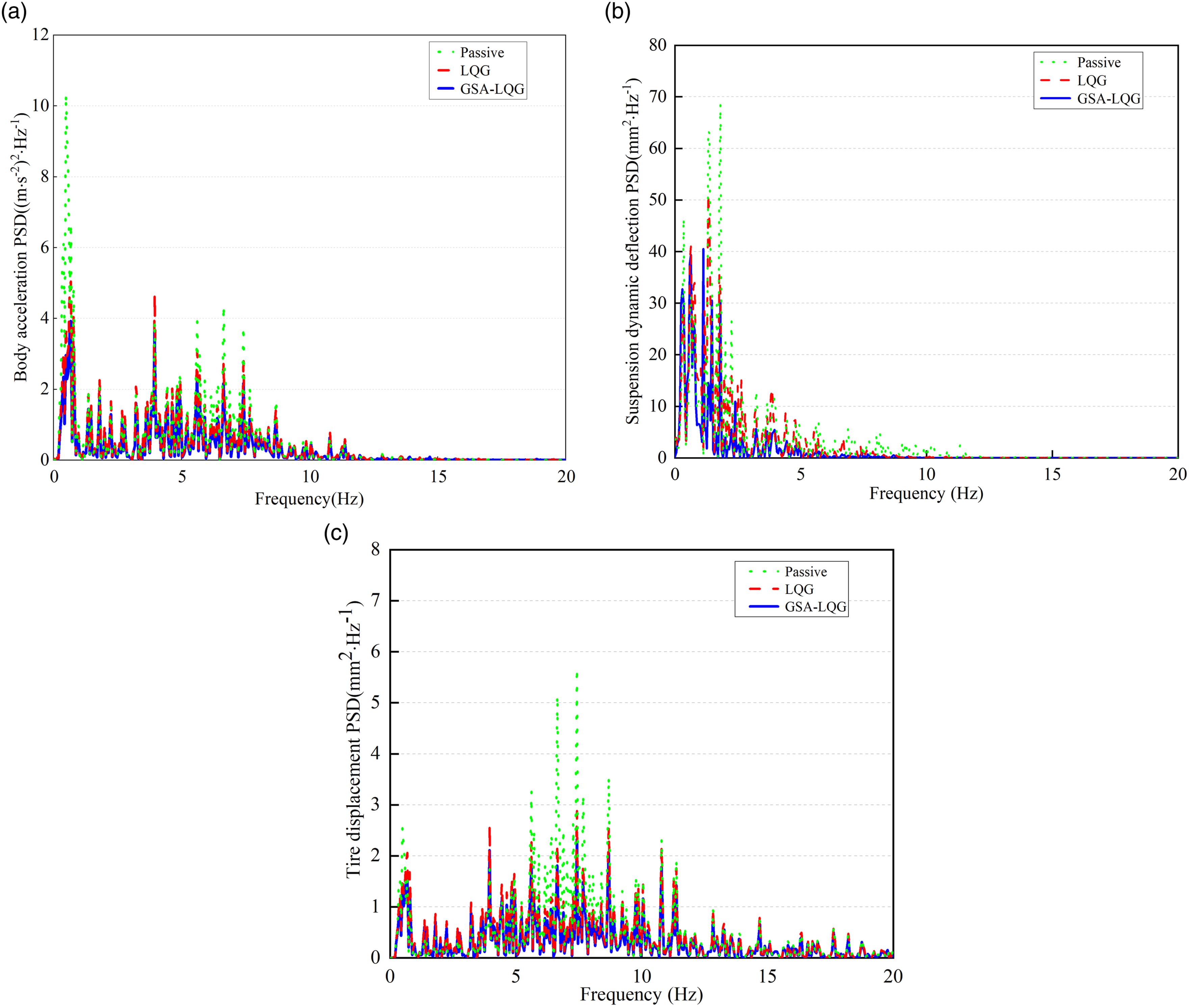
Experimental validation
To further test the dynamic performance of the MR semi-active suspension with GSA-LQG control, Figure 10 depicts the construction of an experimental system for a quarter-car MR semi-active suspension. The suspension test system can provide sinusoidal excitations of different amplitudes to implement the control algorithm, and record important performance parameters. The experimental system mainly includes a 1/4 vehicle suspension test bench, a hydraulic vibration system, a sensor module, and a controller module. Testing system for MR semi-active suspension system.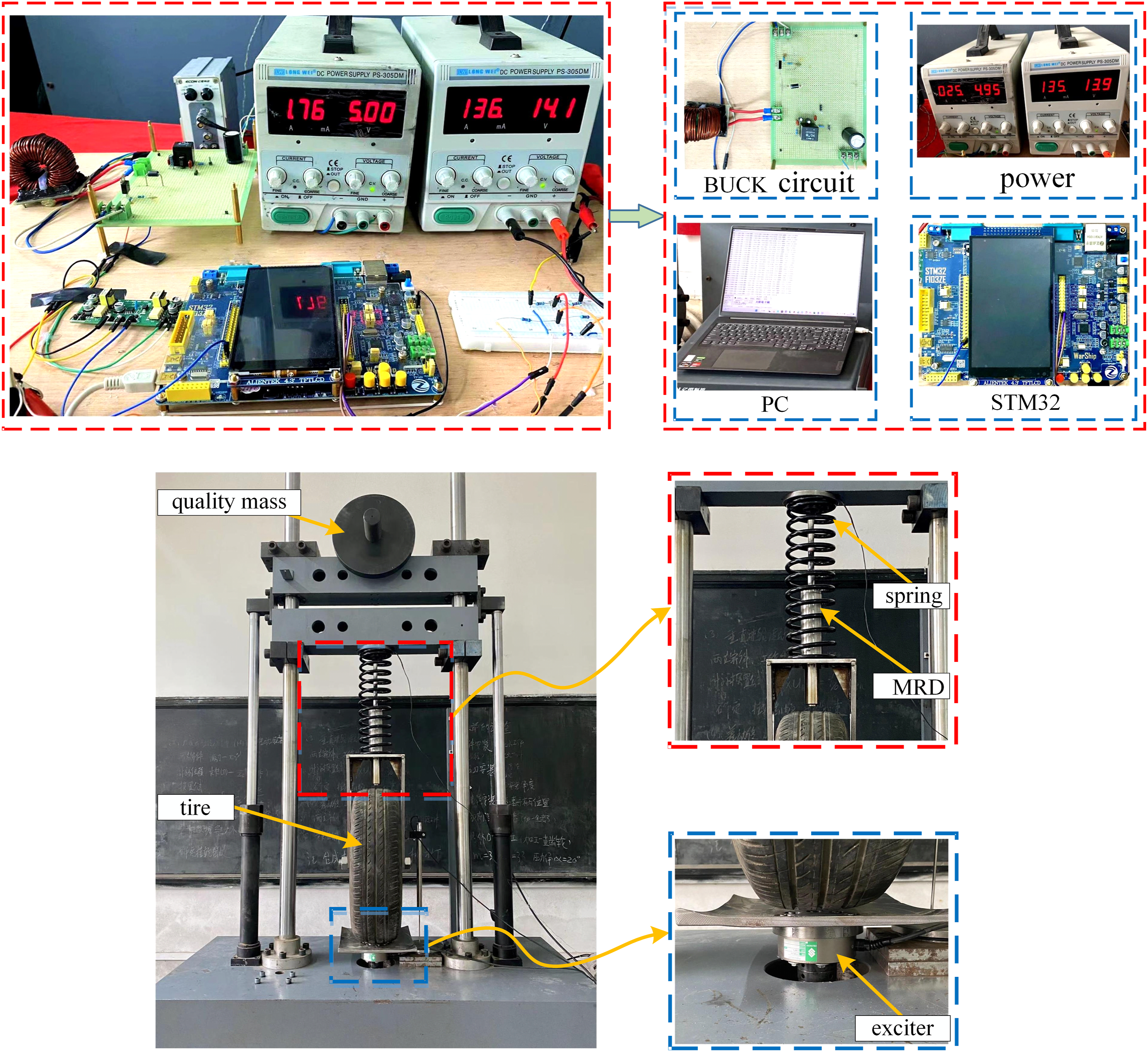
The experimental control principle is shown in Figure 11. The input state signal of the suspension system obtained by the sensor is transmitted to the STM32 microcontroller unit, and the semi-active control algorithm in the control system calculates the corresponding current signal through these state signals, and then converts it into PWM signal through the controller. The BUCK circuit controls the input current to MR damper based on the PWM duty cycle. The current is fed back to the controller for closed-loop control. Ultimately, the MR damper is driven to generate damping force for the semi-active suspension system. The experimental control principle.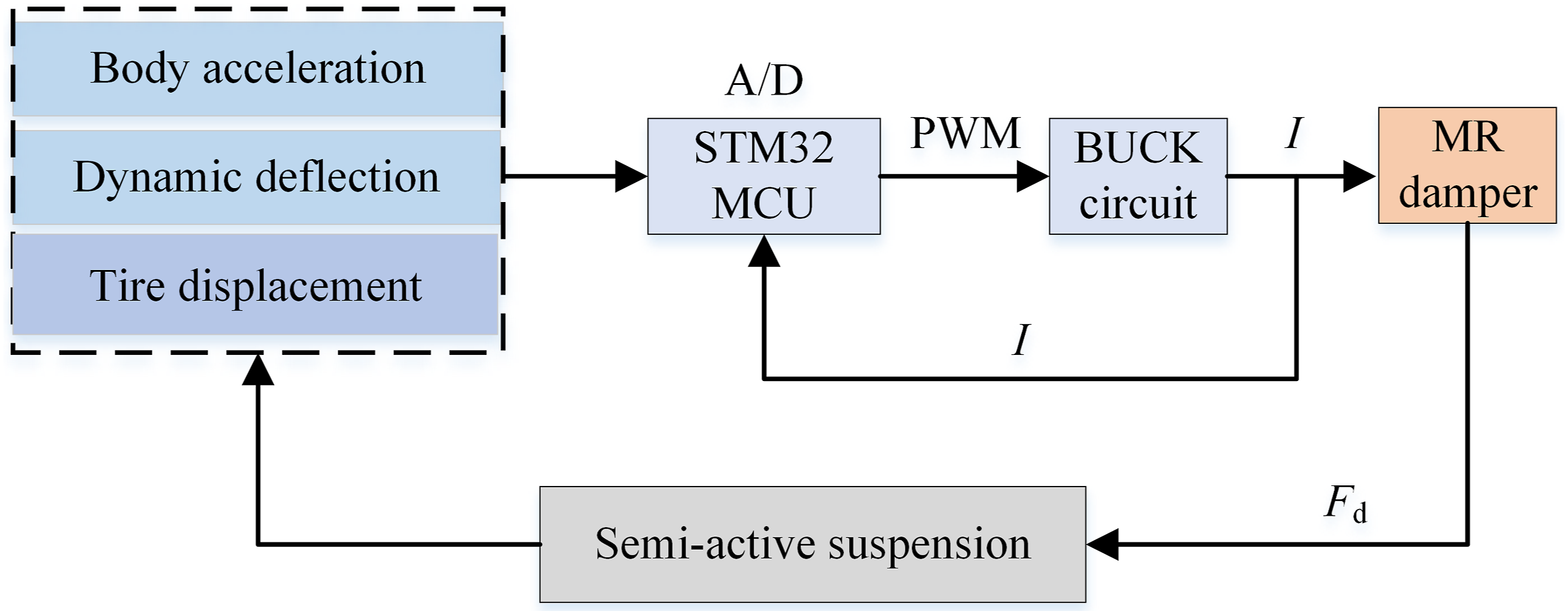
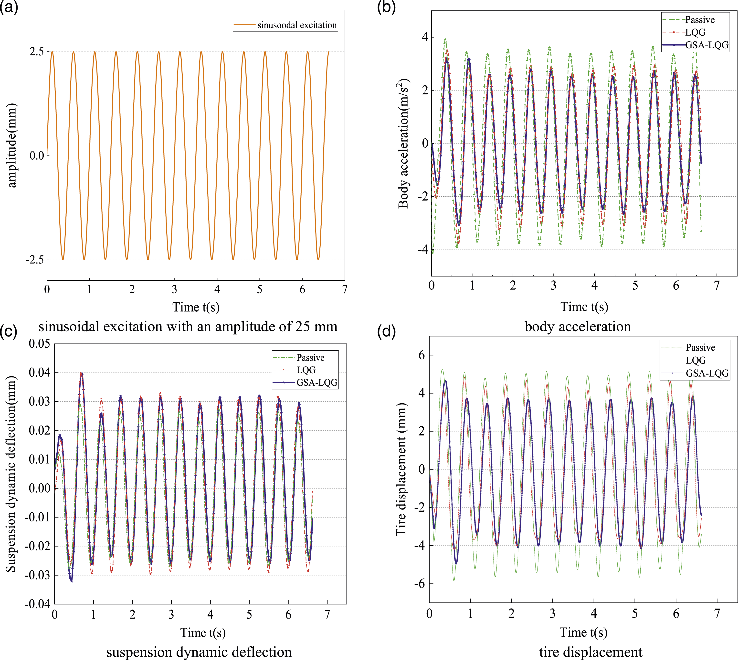
Experimental analyses are carried out to validate the control performance of passive control, LQG control, and GSA-LQG control algorithms on the MR semi-active suspension system. The vehicle suspension experimental platform is subjected to a sinusoidal excitation generated by the exciter, with frequencies of 2 Hz and amplitudes of 20 and 25 mm. The sensor data is used to obtain the experimental curves of three performance indices, namely, the tire displacement, suspension dynamic deflection, and vertical acceleration. In this study, the corresponding weighting matrix coefficients for the GSA-LQG control algorithm are q1 = 75,861.38, q2 = 15,415.53, q3 = 150,162.38. To improve system operation speed, the optimal gain matrix is directly embedded in the program control. The experimental results of passive control, LQG control, and GSA-LQG control under a sine wave excitation with 20 mm and 25 mm amplitude and 2 Hz frequency is illustrated in Figures 12 and 13. Experimental results under 20 mm sinusoidal excitation amplitude. Experimental results under 25 mm sinusoidal excitation amplitude.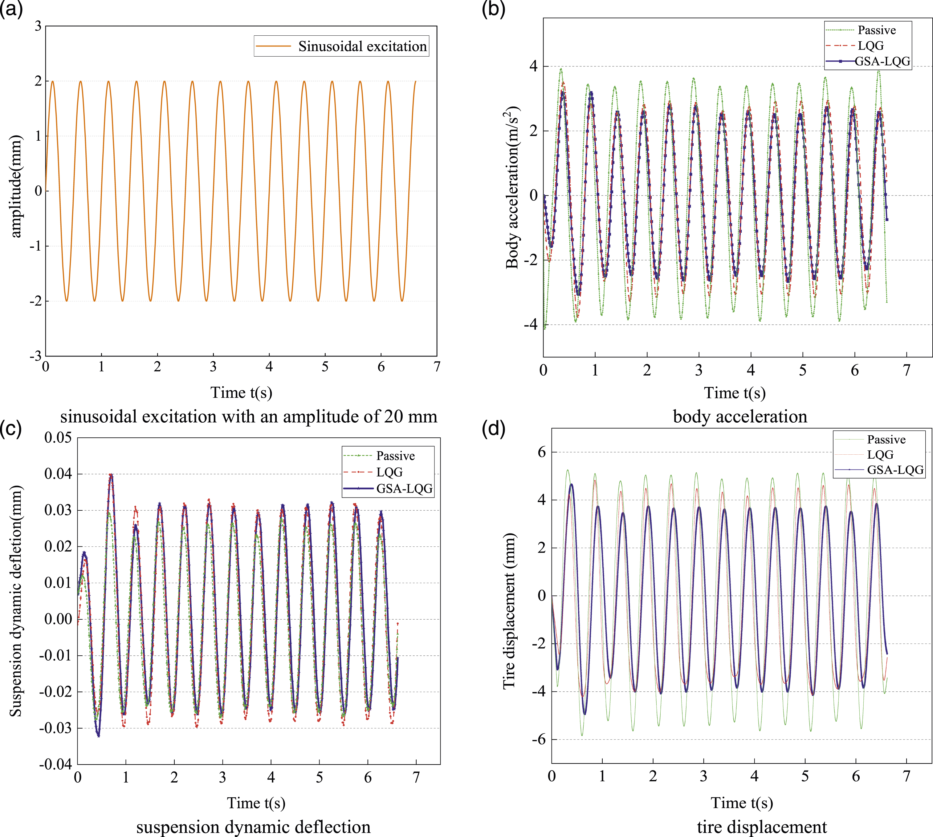
After processing the experimental data, Figure 14 presents the improvement rate of RMS values of different performance indicators under various control strategies compared to passive control. From Figure 14(a), it can be seen the improvement rate of the vehicle vertical acceleration under LQG and GSA-LQG control have reached at 29.7% and 30.2%, respectively, and the tire displacement also improved by 19.4% and 29.6%, respectively. And Figure 14(b) also shows a similar improvement effect under a 25 mm sinusoidal excitation. In the final analysis, LQG control and GSA-LQG control reduce the body acceleration and tire displacement, which improves ride comfort and vehicle stability to some extent. Overall, the LQG control algorithm shows better control performance than passive control, and the GSA-LQG algorithm further improves the control performance compared to the LQG algorithm, demonstrating the effectiveness of the proposed algorithm. However, compared the passive control, both LQG control and GSA-LQG control slightly increase the suspension dynamic deflection, which are increased by 3.8% and 7.1% at 20 mm sinusoidal excitation and 15.2% and 11.4% at 25 mm sinusoidal excitation, respectively. Whereas suspension dynamic deflection remains within the normal working range of the suspension system, and this slight deterioration also indicates that the three performance indicators of the suspension are mutually contradictory and cannot be simultaneously optimized. Instead, one performance indicator must be sacrificed to improve another performance indicator. Performace improvement rate in the RMS value.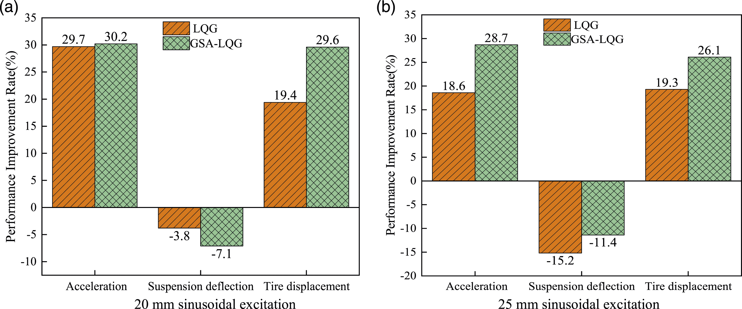
Conclusion
This paper describes the development of a unique GSA-LQG controller for MR semi-active suspension, which includes LQG control and a gravitational search method. The nonlinear dynamic behavior of an MR damper can be accurately described by calibrating mechanical experimental data with the hyperbolic tangent model. Furthermore, a quarter-vehicle model incorporating the MR damper is established. The primary objective of the proposed GSA-LQG controller, based on the constructed model, is to update the dynamic control matrix of the semi-active suspension system. The suggested controller is compared to passive suspension, PID and LQG controllers in terms of vehicle suspension performance, with indicators such as tire displacement, body acceleration, and suspension deflection. The comparison is conducted through simulation and experimental verification. The experimental findings indicate that the PID control, LQG control, and GSA-LQG control enhance the ride comfort and safety of the vehicle suspension. After comparative analysis, it was found that the improvement rate of suspension response achieved by GSA-LQG control is higher than that of PID control and LQG control. Overall, the suspension performance exhibits a more prominent improvement for the proposed GSA-LQG control strategy, and leading to comprehensive enhancements in the semi-active suspension system. This outcome validates our algorithm effectiveness and confirms the feasibility of the experimental platform.
Footnotes
Declaration of conflicting interests
The author(s) declared no potential conflicts of interest with respect to the research, authorship, and/or publication of this article.
Funding
The author(s) disclosed receipt of the following financial support for the research, authorship, and/or publication of this article: This research was financially supported by the National Natural Science Foundation of China (No. 52165004), Key R&D project of Jiangxi Province of China (20212BBE51009), Natural Science Foundation Project of Jiangxi Province (20232BAB204041), Key Program for International S&T Cooperation Project of Jiangxi Province of China (20232BBH80010), Jiangxi Graduate Student Innovation Special Fund Project (YC2023-S463), Double Height Project of Jiangxi Province Human Resources and Social Security Department in 2022.