
Abstract
Defining legislation for electronic prescription systems (EPS) is inherently challenging due to conflicting interests and requirements. The study aimed to develop a comprehensive EPS within the Czech healthcare framework, integrating legislative, process, and technical aspects to ensure security, user acceptability, and compliance with health regulations. A process modeling tool based on hierarchical state machines was employed to create a detailed process architecture for the EPS. Key participants, scenarios, and state transitions were identified and incorporated into a process model using the Craft.CASE based on the BORM methodology. The final process architecture model facilitated interdisciplinary communication and consensus-building among stakeholders, including healthcare professionals, IT specialists, and legislators. The model served as a foundation for the legislative framework and was included in the explanatory memorandum for the draft amendment to the Pharmaceuticals Act. The use of hierarchical state machines and process modeling tools in developing healthcare legislation effectively reduced misunderstandings and ensured precise implementation. This method can be applied to other complex legislative and system design projects, enhancing stakeholder communication and project success.
Introduction
The field of electronic prescriptions and eHealth is a highly complex and intricate discipline that merges expertise and leadership from both healthcare and information technology. Since it is part of the public service and therefore closely tied to the state, another crucial condition for its functionality is required: a legislative framework must be set up to create an environment conducive to the establishment and operation of eHealth. Unlike many other projects, eHealth has numerous specificities due to its handling of sensitive personal data. This places high demands on security measures at both the application and data levels, as well as throughout the entire project architecture, including relevant legislation. At the same time, it is in the public interest for electronic agendas in healthcare to take place, and therefore individual measures must be set concerning their acceptability by individual users.
Architecture and building of information systems and the aspect of related legislation
Both healthcare and information technology have become fields where new specializations and professions are continually emerging. Generally, these two fields are quite distinct from one another. A top analyst or systems architect rarely understands healthcare sufficiently, even in electronic areas like electronic prescriptionprescriptions and eHealth. Similarly, physicians and healthcare professionals tend to be more aligned with the natural sciences than with computers, databases, and algorithms.
Discussions among various interest groups in the health sector (such as insurance companies, patient associations, and doctors’ representatives) should be moderated. It is also essential to describe the various agreements reached in a precise manner that can be translated into architectural tasks for information systems. This description should be presented in an easily understandable format for all professionals involved. Furthermore, the outcomes of these discussions should be applied in the development of legislation.
A process modeling tool based on a patent titled “Method and System for Automated Request Modelling” 1 proved to be an effective enhancement for the Czech electronic prescription system.
This system employs a multi-layered architecture with the process model at the top. The process model provides a detailed definition of interrelated processes in a manner that is understandable to lay readers. The goal is to completely describe all events within the organization (in this case, the Ministry of Health). In many cases, the current state (as-is) is described first, followed by the future state (to-be). However, due to the extensive changes required, both states were described concurrently.
Initially, individual users outlined their requirements, which were incorporated into the emerging architecture. These requirements were written in the same way as communicated verbally before being translated into the process architecture. In commercial projects, this phase is often referred to as business architecture (often also operational/process architecture). For the electronic prescription project, implemented in the government, the term “process architecture” is used. During this stage, initial contradictions emerged, which were refined as the verbal descriptions were translated into precise process definitions. The first version of the process architecture itself resolved some contradictions and inconsistencies. All these refinements and decisions were consulted with the legislative process sponsor at the Ministry of Health.
The uniqueness of this project stemmed from its nature as a state-guaranteed system. Legislative rules define every detail of any health information system in use. Therefore, the related legislation must be impeccable and closely linked to the proposed process model of the intended health information system. The roles and required responsibilities of different actors must be clearly defined. If the design is flawed, some parts of the intended service might not be implemented, or entities might not be required to use it in the case of a mandatory system.
The main objective, apart from the actual design of a specific health information system, is to create a comprehensive definition of the entire environment, including relevant legislation. This definition should be established taking into account current trends in software architecture, acceptable professional healthcare practices, and patient requirements. 2
The Czech electronic prescription system and change management
The first legislative attempts to enable electronic prescription in the Czech Republic date back to 2006. In 2007, the State Institute for Drug Control (SIDC) was authorized by law to develop and manage an electronic prescription system (EPS) starting in January 2009. At that time, the law established only a few basic rules for EPS, including the admissibility of electronic prescriptions and the existence of a basic repository of electronic prescriptions governed by SIDC.
The Czech EPS, named eRecept, was launched in May 2011. The system architecture at that time consisted of a basic server with central storage and a defined interface. Physicians issuing an electronic prescription or pharmacists dispensing medications based on these prescriptions needed end-user systems, which were expected to be obtained from commercial vendors. The only function of the EPS was to store the prescription and issue an identifier, printed as a barcode on the prescription form. This identifier was scanned at the pharmacy to retrieve data from the central repository. Although this implementation is consistent with the basic EPS definition, 3 it lacked advanced features such as lists of dispensed medication or even checking for adverse drug interactions. A qualified electronic signature was required to authenticate each user. At that time, using the Czech EPS was voluntary for both patients and physicians.
After its introduction in 2011, no new functions were developed, and the system’s usage remained very low for several years, with single-digit percentages of all prescriptions issued and physicians using electronic prescriptions. This was most likely due to the lack of advanced features, as most users saw no reason to use the EPS. The political representation decided to increase its use by making it compulsory for all physicians and pharmacies, limiting traditional paper prescriptions to certain situations. This mandate was initially set for January 2015 and later moved to January 2018.
Although controversial at the time, the mandatory use of EPS significantly increased system usage, with the proportion of electronic prescriptions rising from 2% in 2016 to 80% in 2018, and the proportion of physicians issuing electronic prescriptions similarly rising from 5% in 2016 to 84% in 2018. This change cannot be attributed to other factors than the necessity of EPS, as no new functions or significant changes were introduced during that period. 4
With much broader usage of EPS, SIDC began improving the system. Robustness was increased by adding a third data center, and electronic prescription identifiers could be sent by email or SMS. Each patient was given access to the list of their prescribed medications via a simple web or mobile application. Among the advanced functions, a medication list accessible to both physicians and pharmacists was considered the most useful – many other EPS in the European Union at that time had already implemented this feature. 5
However, this functionality could not be introduced solely by SIDC. In the Czech Republic, it is not possible to share personal health data without specific legal provisions, which did not exist at the time. Therefore, a new law had to be drafted to allow the sharing of medication lists. This draft law needed to include detailed mechanisms for data sharing and ways to limit and regulate professionals’ access to the data. To preserve patients’ rights, the main focus was on how patients could refuse access to their data and whether to use an opt-in or opt-out model, as both have advantages and disadvantages. The bill also aimed to better define electronic prescriptions in Czech legislation and ensure that the EPS did not conflict with existing Czech law.
Materials and methods: Hierarchical state machines and state diagrams as the basis of electronic prescription process architecture
We work on projects based on state machines and their superstructure in the field of process modeling. Therefore, we decided to apply this approach here, as state machine modeling appeared to be an effective method for addressing this complex problem.
State machines are widely used in computer science, for example as in lexical analyzers within compilers. However, their application is much broader. They are generally used to describe the dynamics of a system. By using state machines, we can describe real-world dynamic processes in a relatively simple and generally and graphically comprehensive way, breaking down the complex behavior of individual objects into a finite number of states.
In a state diagram, we first graphically represent individual states (represented by green-bordered rectangles) and then connect these states with transitions. A transition from one state to another is triggered by an external event, and during this transition, an activity (shown by a pink rectangle with rounded edges) is performed. A transition can also loop back to the same state. When defining a state machine, one state is always designated as the initial state, where the object starts. A final state can be added to represent the completion of the process.
Using state diagrams to describe the behavior of information systems has proven very useful for creating process models related to legislation. Creating such models requires multidisciplinary collaboration with experts—in our case, the medical community provides the necessary expertise. State diagrams enable us to precisely depict real-world scenarios or legislative requirements as described by experts. Although laypersons (such as lawyers) might not initially understand these diagrams, with proper explanation, they can learn to work with them and appreciate their clarity and explanatory power.
Hierarchical state diagrams, or statecharts, are particularly useful for visualizing the behavior of complex systems. However, their construction requires significant effort when the system is not well-defined, as was the case with the EPS. Classical single-level state machines are insufficient for describing complex systems, necessitating enhanced semantics.
The development of hierarchical state diagrams was driven by a need for better visual representation, as seen in projects such as the creation of software for aircraft avionics for the Israeli Air Force. 6 This complexity led to the development of hierarchical state machines, where a state can contain another state machine or multiple state machines running in parallel.
Harel’s approach to hierarchical state diagrams has been well received by the professional community. His notation and its various versions have been incorporated into many methodologies and software tools for process modeling. For example, MathWorks integrated Harel diagrams (with some modifications) into its “Stateflow” tool, linking them with Simulink and MATLAB. Hierarchical state machines are also part of the standard Modelica language library.
Due to our positive long-term experience, we used the Craft.CASE tool and its formalization method based on the BORM methodology 7 to describe systems that are not fully known and well-defined.
The design principle of the process model is divided into six phases: • Interview: Informal discussions of the problem using sketches. • Definition of the Process Architecture: Structure of things. • Setting the Links. • Testing. • Process Diagrams. • Final Validation: Simulating the whole model.
The above paradigms were used to create the electronic prescription model. The BORM process model is especially useful in cases of unclear processes in an environment characterized by the frequency of change. Its clarity helps laypersons understand the context between processes and system linkages. At the same time, the BORM process model facilitates discussion among various opinion groups involved in a process, even those unfamiliar with the notation, due to its ease of understanding.
The aim was to design the basic structure of processes and to define a complete hierarchy of processes as a structural superstructure of basic state machines and hierarchical state machines. This approach enabled the creation of a communication environment that is not only suitable due to its mathematical basis but also features an intuitive interface, suitable for discussions with experts without requiring training or explanation of the methodology.
Results: Process model as a tool for discussion of the final solution
We used BORM state diagrams and process models like an imaginary “pencil” to draw the process architecture of the electronic prescription system. The resulting process architecture diagram then served as a communication tool for interdisciplinary understanding.
The first step in the BORM methodology involved informal discussions of the problem. The informal assignment was then progressively translated into a formally and substantively correct process solution and the design of an information system to support the identified processes.
The following modeling phases were used for the electronic prescription system: 1. Sketches 2. Process Architecture 3. Process Diagrams
For complex systems, it is essential to record as much information as possible at the beginning of modeling. Strict adherence to formalism could result in missing important messages, so sketches are initially used to capture information. At this stage, the initial “model” was created only on paper, resulting in an almost non-reproducible scribble. However, years of experience have shown that going through the “scribble, erase, throw” phase is crucial for finding the “right” elements of the later real model, as a deeper understanding of the issue and context emerges over time.
During this phase, the main procedural participants were progressively identified and confirmed: the patient, the physician, the pharmacist, the electronic prescription system, and the necessary procedural part of the consent procedure. At the same time, the main states of the process participants were also identified. For example, the patient could be “treated by a physician” or “requiring an electronic prescription to be issued remotely,” and the prescription could be “created in a paper form” or “created in an electronic version.” It could also have been “issued” (meaning the medicine has been dispensed, including cases where a substitute medicine was dispensed).
Close and functional cooperation with future users and regulators is necessary in the initial phase of modeling. Without detailed knowledge of all possible conditions and legislative requirements for prescribing in the Czech Republic, success is impossible. This knowledge is typically not available to information systems architects.
In the sketches phase, it is important not to engage in debates about who does what, as these are ultimately unproductive at this early stage. Instead, it is crucial to track who is entering which state (see the examples of states given in quotation marks above).
The next step is to check the possibility of combining the defined states of each participant into one or more “stories.” This means that individual events occurring in the system can be described by the elements of the model created. At this point, the formal phase of architecture begins, transitioning the process architecture from a sketch to an assembled diagram.
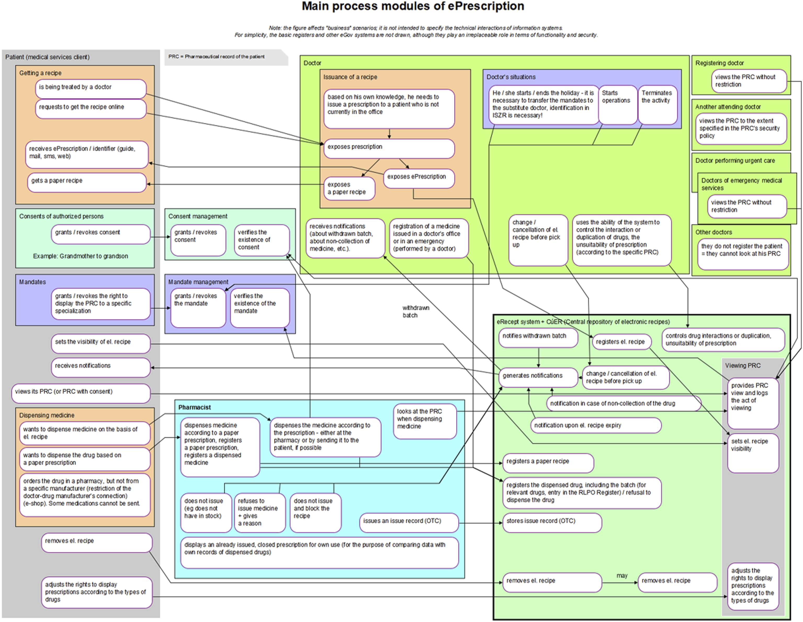
The process architecture diagram formally displays: • Process Participants: For example, Patient, Physician, Consent Management. • Scenario Groups: Consisting of simple stories, such as Obtaining a Prescription, Dispensing Medicine. • Scenarios: Individual stories. • Links Between Scenarios: Represented by arrows.
In the process model, each scenario, in addition to the name, is characterized by three descriptive elements in addition to its name: • Initiation: Describes the status of the process participant when the scenario is activated. • Actions: Describes the actions performed within the scenario (e.g., the pharmacist converts the paper prescription to electronic form and processes it accordingly). • Result: Describes the status of the process participant after the scenario is completed.
The links between the scenarios show how the individual scenarios performed by the process participants follow one another.
The sketch phase provided sufficient knowledge of the issue and enough refined ideas. Initially, a simple prescription drug model was prepared (as shown in Figure 1), which subsequently evolved into the first process architecture diagram (Figure 2). When this initial version of the main process modules was presented at the first joint meeting, it had a surprising effect. Although the diagram was certainly not perfect, it provided participants with a concise, clear, and comprehensive view of the electronic prescription issues being addressed, the involved parties, their interactions, and potential situations that might arise. This diagram served as a unique basis for discussion, albeit still imperfect. Participants’ feedback was gradually incorporated, leading to subsequent versions were submitted. The tenth version proved to be the final one, as seen in Figure 3. Simple initial model of electronic prescription. Initial version of the diagram of electronic prescription process modules. Final diagram of electronic prescription process modules.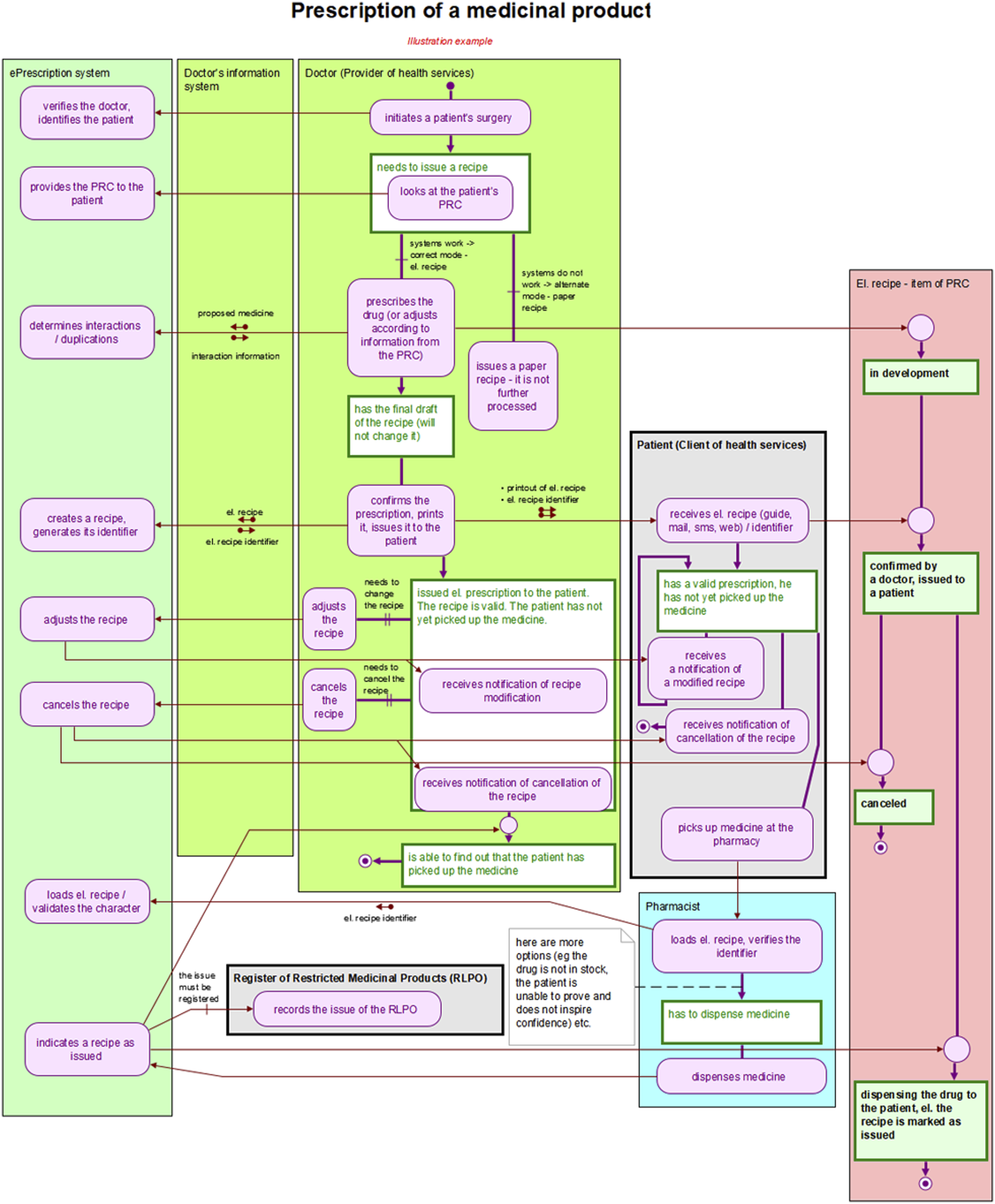
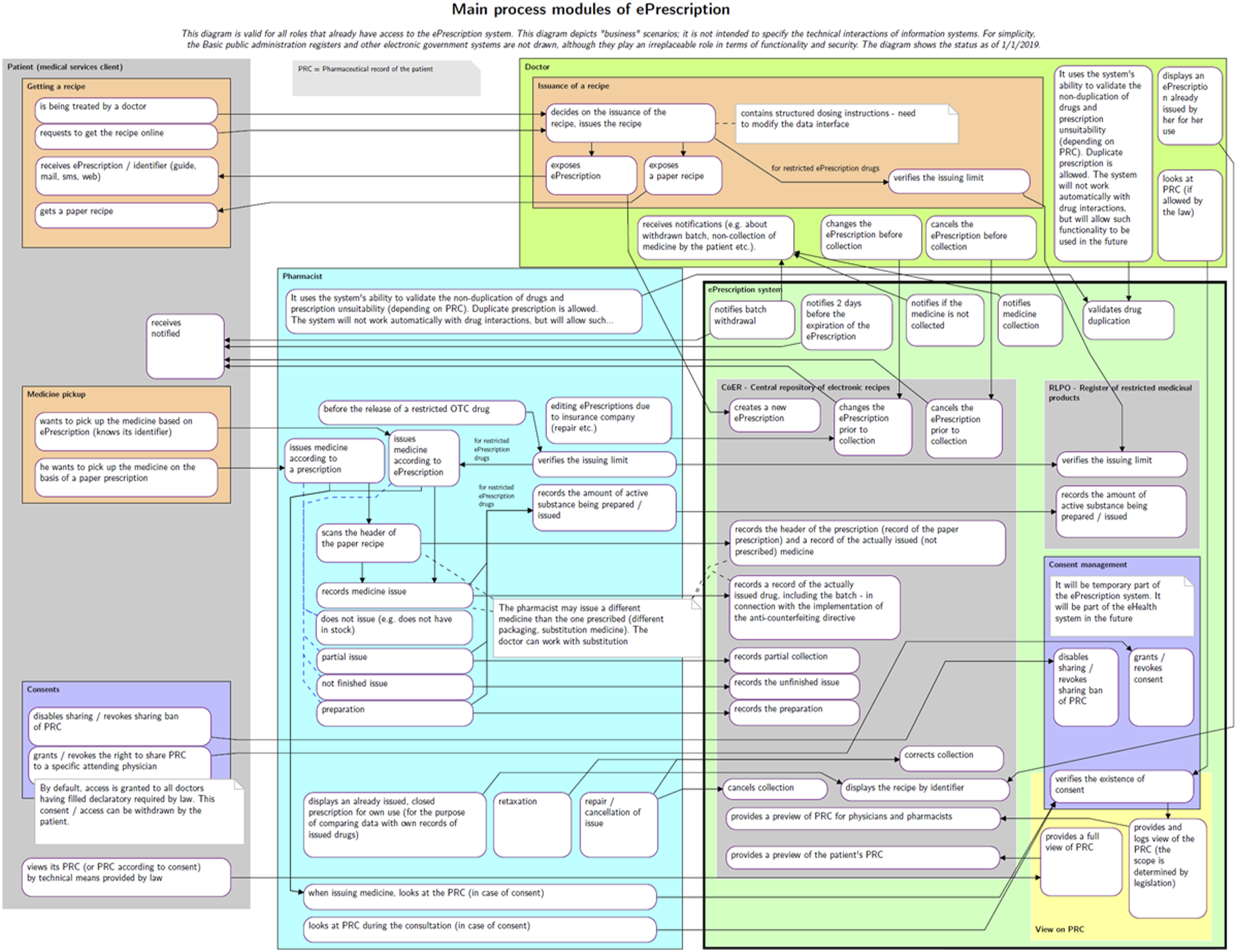
This final version of the diagram was included as an annex to the explanatory memorandum for the draft amendment to the Pharmaceuticals Act, which introduces and describes the EPS. The proposal was adopted by Czech legislators and became effective on 1 December 2019.
Discussion
Introducing technological and digital innovations into the healthcare sector requires careful and well-thought-out change management (CHM). It can be said that planning, evaluating, and managing change is as crucial as the innovation itself, ensuring the desired benefits and outcomes. Key factors for successful CHM include a clearly defined and widely communicated vision, early involvement of all stakeholders, clearly defined rules, adaptation to the local context and culture, provision of technical support, and gradual implementation with strong feedback. 8
Unified Modeling Language (UML) is often used for modeling in health-related professional articles, but its expressions can be ambiguous and open to multiple interpretations. For our purposes, we decided to use the BORM methodology, implementing BORM state diagram notation, which provides clearer and more precise modeling.7,9
Process modeling has been previously used in healthcare to represent current situations. For instance, UML process modeling has been employed to describe population analysis and proposed measures in research on obstructive sleep apnea, 10 and to detail specific care and treatment of pediatric asthma patients, 11 as well as healthcare processes within a hospital. 12 However, we used process modeling not to depict the current state but to design a completely new process for the entire health system, forming the basis for defining the EPS legislative model.
New processes have been designed using modeling tools before, such as in the establishment of standardized processes in breast cancer screening. 13 However, these models were typically used to describe processes, whereas we used them to build consensus among different actors in the health sector while developing legislation, requiring several rounds of model sharing and refinement.
In social care, process modeling has been used to describe and standardize the custody process for children of separated parents, optimizing and accelerating care. 14 However, unlike our case, these process diagrams were not used as an annex to legislation.
Business Process Model and Notation (BPMN) has been used to verify GDPR compliance, 15 but only to describe existing legislation. In contrast, we used process modeling to define the basis of a legislative norm.
Our approach is characterized by the use of hierarchical state machines-based business process modeling in developing healthcare legislation. Thanks to complex discussions among different interest groups in the healthcare industry, we produced the final version of the legislation within 3 months. We believe this approach is novel and can be applied in the future, not only in healthcare and not only in our country.
In designing the electronic prescription, we dealt with a process-oriented and predictable system, supported by a computerized information system. This allowed us to focus on structured processes rather than unpredictable, unrepeatable, weakly structured, and knowledge-intensive. Moreover, we were only dealing with the process side of the issue. This fact fundamentally influences the choice of tools. Thus, this discussion is conducted in comparison of BORM and BPMN and does not include DMN and CMMN from the BPM + initiative.
BPM tools use the concept of flowcharts to represent the process. While flowcharts are simple and easy to read, they does not accurately reflect modeled reality. Major limitations include a single storyline from which the life cycle of each process participant is difficult to derive and the absence of “process clues” that allow quick orientation in a process that may be structurally complex, long, or structurally complex and long.
In contrast, BORM does not present processes as flowcharts, but as so-called process and link diagrams. The reason is that flowcharts are not able to capture complex interrelationships between activities of individual process players. It happens that flowcharts do not reflect reality completely and uncontroversially, and in practice, people do not know what exactly to do, who does what, when, from whom to get what, and what to give to whom, etc. This is one of the main differences between BORM and tools showing processes in the form of (albeit improved) flowcharts.
BORM diagrams include: • Interaction of Process Participants: Displaying communications between participants. • Data Being Transferred: Showing what data is communicated and how it achieves the outcome. • Life Cycle of Each Participant: Describing the states and activities experienced by each participant.
BORM’s simplicity and intuitive symbols make the diagrams easy to understand for an untrained reader. Unlike BPMN, which may require multiple diagrams to show different aspects of a process, BORM provides a clear and comprehensive view in a single diagram.
In the case of a BPMN or BPM + representation, these aspects may not (usually are not) shown in a single diagram, making the process notation less readable and understandable.
If we describe a process with only one storyline, it is too easy to make a mistake without realizing it. An elementary example is that if one participant waits for another to take action (by the way, “waiting” is not painted on BPMN diagrams at all), he doesn’t have to wait indefinitely - when he gets tired of waiting, he will take some action.
This is not to say that the above cannot be drawn on a BPMN diagram: of course, it can be drawn, but it is up to the knowledge, experience, responsibility, and state honor of the modeler to put it on the diagram or to forget it (consciously or unconsciously). In our practice using the BORM method, we found that flowchart-based analyses serve only as inputs to the BORM analysis. It is risky to develop software based solely on flowchart descriptions of a process, as BORM provides a more precise and reliable foundation for process modeling and subsequent system development.
Conclusions
The process architecture model, represented as a graphic scheme, has proven to be a valuable communication platform, facilitating discussions among stakeholders, including regulators. Each stakeholder has different interests and backgrounds, making a clear and common understanding crucial.
In our case, the model was used for legislation, but it can also be directly applied to defining and building an information system. The process modeling tool can be used to describe a conceptual software model and capture its links to the processes and requirements of information system users. This approach helps eliminate misunderstandings between system users and IT support, which are often major causes of project failure.
Testing the proposed process model before making any decisions with potentially irreversible or costly consequences is essential. The process architecture model is comprehensible to all users, IT professionals, legislators, practitioners, and other participants in professional discussions.
Compared to conventional methods, our approach has shown that using process modeling to draft legislation on complex issues like electronic prescriptions significantly simplifies the process. It reduces the risk of misunderstandings, inaccuracies, and errors, while allowing authorities to maintain control over the entire process. The process architecture model ensures consistency, accuracy, and simplicity.
The method described in this study was subsequently used to incorporate COVID-19 vaccination information into the Czech EPS. The vaccination record process model was developed in just 3 weeks, and the legislation was passed within two months—a remarkably efficient timeline compared to conventional methods, which typically take over a year. 16
Footnotes
Declaration of conflicting interests
The author(s) declared the following potential conflicts of interest with respect to the research, authorship, and/or publication of this article: A.V. is a former Czech minister of Health.
Funding
The author(s) received no financial support for the research, authorship, and/or publication of this article.
Ethical statement
The study does not involve any patient-specific data or personal health information and is therefore exempt from requiring ethical approval.