
Abstract
The construction sector is showing renewed interest in prefabrication, particularly in modular construction and building systems based on precast walls. This is mainly due to the current lack of workmanship and construction time. Prefabrication allows for faster construction and more efficient on-site assembly without compromising structural performance. In this context, an innovative eco-efficient precast wall system was developed, combining ultra-high durability concrete with low-cement lightweight aggregates concrete. This paper presents a study addressing the development of novel dry-connections, designed to facilitate the assembly and disassembly of the referenced precast walls, promoting this way the potential reuse of structural elements. The connections were designed to avoid on-site casting, thus significantly reducing workmanship needs. Three new bolted connections were tested for vertical joints between precast walls, considering the tolerances required for the assembly process and the stiffness, strength and ductility necessary for the structural performance. Monotonic tensile tests were conducted to evaluate their structural behaviour. Results show that all connections can effectively transfer a concentrated tensile load to the concrete wall, with limited cracking under service conditions. The main conclusions are presented, together with recommendations for quality control during production to ensure reliable system performance.
Introduction
Today’s urgent need for housing in Europe, mainly in touristic cities, the increasing occurrence of extreme events (e.g. hurricanes, floods, pandemics), exacerbated by climate changes, and armed conflicts in different parts of the globe lead to the need to provide affordable housing and shelters in a fast, safe and cost-effective way (Martins et al., 2023). In addition, there is a concern for more durable and sustainable solutions, which can be reached especially by reducing the cement content (Tavares et al., 2021). Precast concrete structures have been widely used because of their many advantages, such as high quality, high durability, faster erection and lower workmanship needs, when compared with traditional on-site constructions (Gallo et al., 2021; Guo et al., 2019). Over the last decades, several companies located in Europe, Asia and the United States advocated precast concrete systems for the construction of both residential and industrial buildings. When compared with other structural systems (e.g. wood or steel), the present benefits in terms of higher durability, lower maintenance, better fire resistance and better thermal insulation (fib (Task Group 6.7), 2011). Precast structural walls are one of them, with competitive advantages compared to other precast systems, making it possible to build quickly and easier without the need to use other structural elements, such as columns or beams (Chen and Poongodi, 2020; Martins et al., 2023). These elements can support vertical and lateral loads, such as earthquakes and wind actions (Dazio et al., 2009; Pavese and Bournas, 2011). According to Martins et al. (2023), based on a literature review on different commercial solutions and research studies, the precast walls can be organized into different types, according to their cross-section, being one of them the double/composite walls, which take advantage of the main properties of the different materials that constitute the wall to improve its performance. Having in mind the abovementioned, together with the outcome from previous studies (Carmo et al., 2023; Martins et al., 2021), this paper introduces an innovative composite wall system with a structural function for buildings (Figure 1) (Martins et al., 2023, 2024a; Martins et al., 2024b). This system aims to take advantage of the concrete properties, maximize the benefits of the prefabrication sector, improve the sustainability of structures, decreasing the carbon footprint in concrete structures, and increasing their durability (Martins et al., 2024b). The proposed wall is composed of two different layers, using two different types of concrete: (i) an optimized ultra-high durability concrete (UHDC), to be used as a thin cover layer; and (ii) a low cement lightweight aggregate concrete (LCLWAC), for the inner layer; both developed for this specific purpose (Martins et al., 2024a). This new solution reduces the weight of the walls and consequently of the structures, by using lightweight aggregates, and it increases their durability, with the “super-skin” concept (Ghafari et al., 2012; Martins et al., 2020; Robalo et al., 2021), which consists of using a high durability concrete only in the outer layer of the elements. In addition, it improves the member’s sustainability, with a lower carbon footprint resulting from the use of a concrete with reduced cement content in the core. Special attention has been given to the LCLWAC-UHDC interface to ensure there is no slippage between them and to guarantee proper structural performance (Martins et al., 2024b). UHDC-LCLWAC composite precast walls and bolted-connections.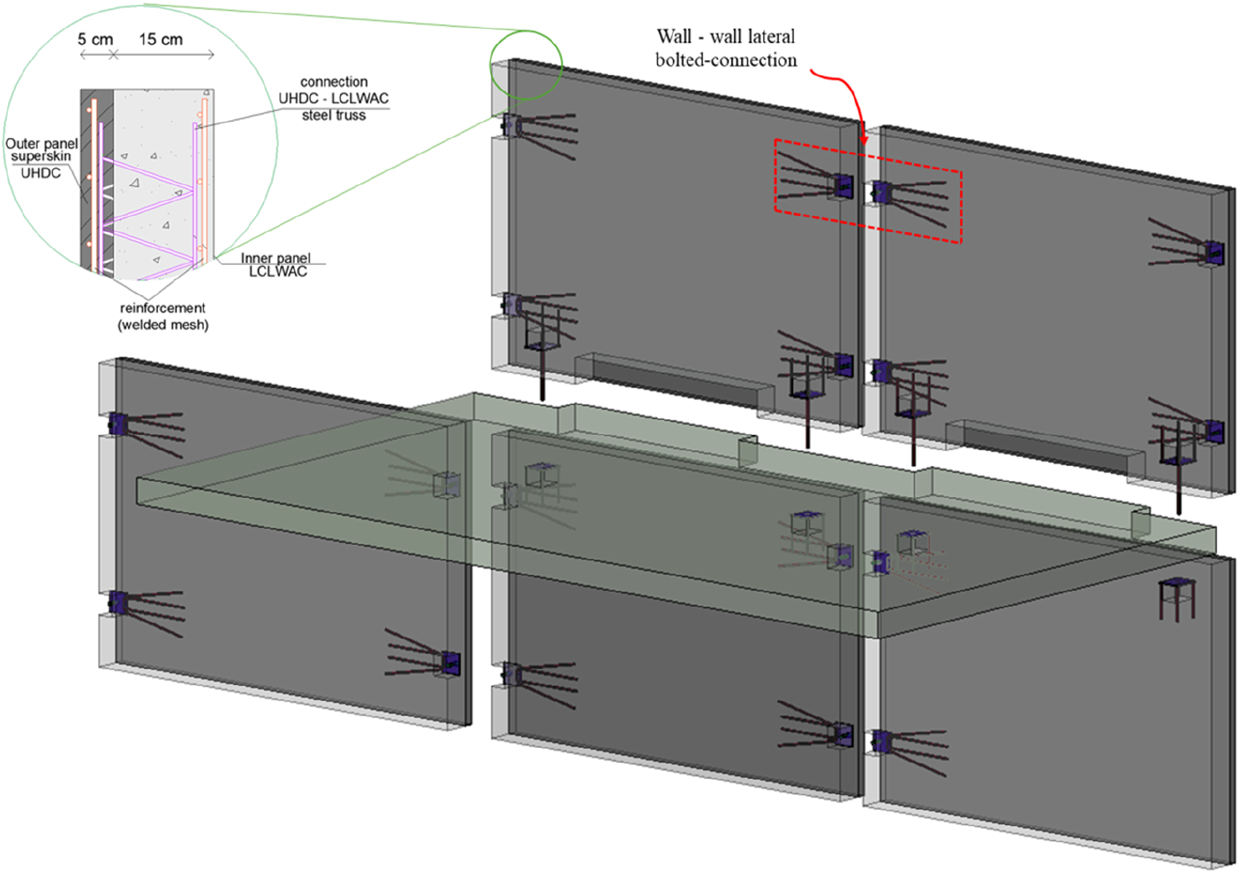
In the proposed system, the prefabricated walls, and other structural elements, are connected to each other using vertical and horizontal dry-connections (bolted). The design of these connections is one of the most crucial factors in the structural design of precast buildings, as they play an important role in the lateral strength of the precast wall system (fib (Task Group 6.2), 2008; Hemamalini et al., 2021). Typically, the connections in precast elements can be divided in [5]: (i) wet-connections or (ii) dry-connections (Martins et al., 2023). Wet-connections are created using on-site casting concrete, working together with steel reinforcement. This type of connection allows the construction of structures with monolithic behaviour, ensuring a continuous transfer of forces between the precast walls (Cai et al., 2019). However, since the creation of these connections involves some on-site tasks, execution and quality control can be conditioned by environmental conditions. Also, the possibility of disassembly is not feasible, and thus, instead of deconstruction, demolition has to be adopted like structures build on-site, compromising the sustainability of the structure, with a clear negative effect in the life cycle assessment of the latter (Martins et al., 2023). Alternatively, dry-connection using steel connectors (bolted or welded), can be adopted to assemble the precast elements with several advantages. In fact, these mechanical connections have the right characteristics to respond to the actual construction needs and the goals defined for the precast wall-based structural system herein presented, namely: (i) easy and fast execution; (ii) easy access to the bolted-connection and consequently less maintenance required; (iii) less on-site workmanship; (iv) disassembly enabled, useful for buildings with temporary use (e.g. shelters and filed hospitals); (v) easy repair/replacement in case of extreme events; and (vi) end-of-life benefits, allowing deconstruction and collection of materials for reuse and recycling (Singhal et al., 2019). Nowadays, there are different types of dry-connections available (Martins et al., 2023). (Brunesi and Nascimbene (2017) developed an anchoring system composed of threaded bolts and steel plates, designed for lateral connections between walls in low-rise residential buildings. Results showed that the connections are the weakest link of the system, since all specimens collapsed due to the vertical connections. This experimental study was essential to improving the initial connection design. Cai et al. (2019) proposed a bolted-connection, in which bolts pass through the wall and are connected with steel plates on both sides. Results obtained showed that the number of bolts and tightening process have influence on the strength capacity of the connections. Psycharis et al. (2018) studied the ‘wall shoe connection’ system for horizontal connections, based on a commercial solution. The results show that the connection can achieve high ductility and strength, but with significant pinching for high lateral displacements. Taheri et al. (2016) and Vaghei et al. (2019) studied a system composed by male-female walls. This was an upgrade of a wet-connection, designated as ‘loop connection’, and the results showed an increase of the maximum strength. Sun et al. (2019) developed an H-connection and used high strength bolts to connect adjacent walls and floors. The results of the experimental campaign showed a greater performance under monotonic loads. Lim et al. (2016) presented a precast T-wall system with C-shaped steel plate connection, concluding that the proposed connection is robust and practical. Finally, Guo et al. (2019) proposed a solution with plates anchored to the wall using steel rebars, being the connection made of plate-to-plate and bolts. The experimental results show that the failure mode was dominated by anchored rebar ductile rupture.
Based on the state-of-the-art about precast connection in wall’ systems, and considering the previous works carried out by the authors, the main goal of the study herein described was to develop an innovative bolted connection, specially designed to be used in vertical wall-to-wall joints in the precast wall-based system adopted and herein discussed. These connections are designed to allow multidirectional adjustments during on-stie assembly and incorporate a novel anchorage reinforcement configuration to enhance the mechanical bond and interaction with the concrete. Alternative vertical connections between the walls, and between the walls and the slabs and foundations, are being developed in other parallel studies. The main assumed challenge is to make both the stiffness and the strength that are needed for the structural performance compatible with the required tolerances for the assemblage. Furthermore, it is important to ensure a proper transmission of forces between the bolted connection and concrete to avoid wide cracks, namely in service conditions, as well as sufficient strength and ductility to ensure an adequate performance and to avoid brittle failures under extreme loads (e.g. seismic). Therefore, to accomplish the goals, three different dry-bolted connections were developed and tested. This paper describes the new dry-connections developed for precast composite concrete walls and the experimental study conducted to characterize their behaviour under tensile monotonic loads.
Description of dry-connections solutions
The proposed precast wall panels with dry-connections are designed as load-bearing structural elements for building systems in which walls contribute to both vertical load transfer and resistance to horizontal actions. Gravity and horizontal loads are transmitted through the panels and the dry-connections, which ensure effective force transfer under combined actions. Depending on the building typology, the system may function as a primary structural system or be integrated into a hybrid structural solution.
The proposed connections in this study consist of anchored steel plates and high-strength bolts organized in different ways (see Figures 2 and 3). The three bolted connections were specifically developed to laterally connect the walls (Figure 1). Although presenting different arrangements, they all feature identical connection plates with dimensions 130 × 130 × 12 mm3, steel S275 and high-strength M20 8.8 bolts whose properties are detailed in Table 1. Steel plates surface: (a) smooth; and (b) indented. Lateral wall-wall dry-connection: (a) Connection-1; (b) Connection-2; (c) Connection-3. Key: (1) UHDC layer; (2) LCLWAC layer; (3) anchored rebars, welded to the plates; (4) steel plates, with oval holes; (5) steel plates, with welded bolts. Main characteristics of the M20 8.8 bolts.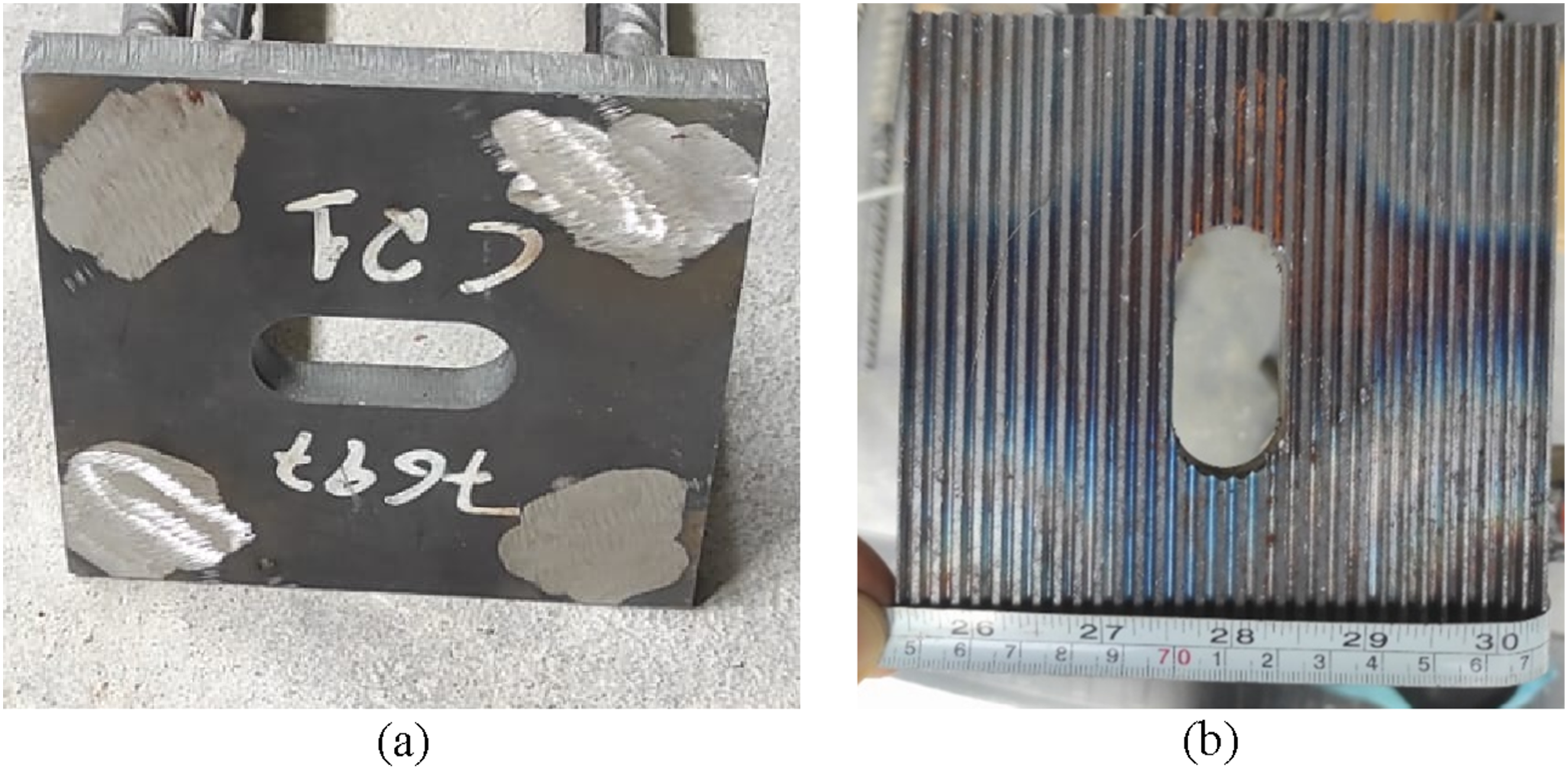
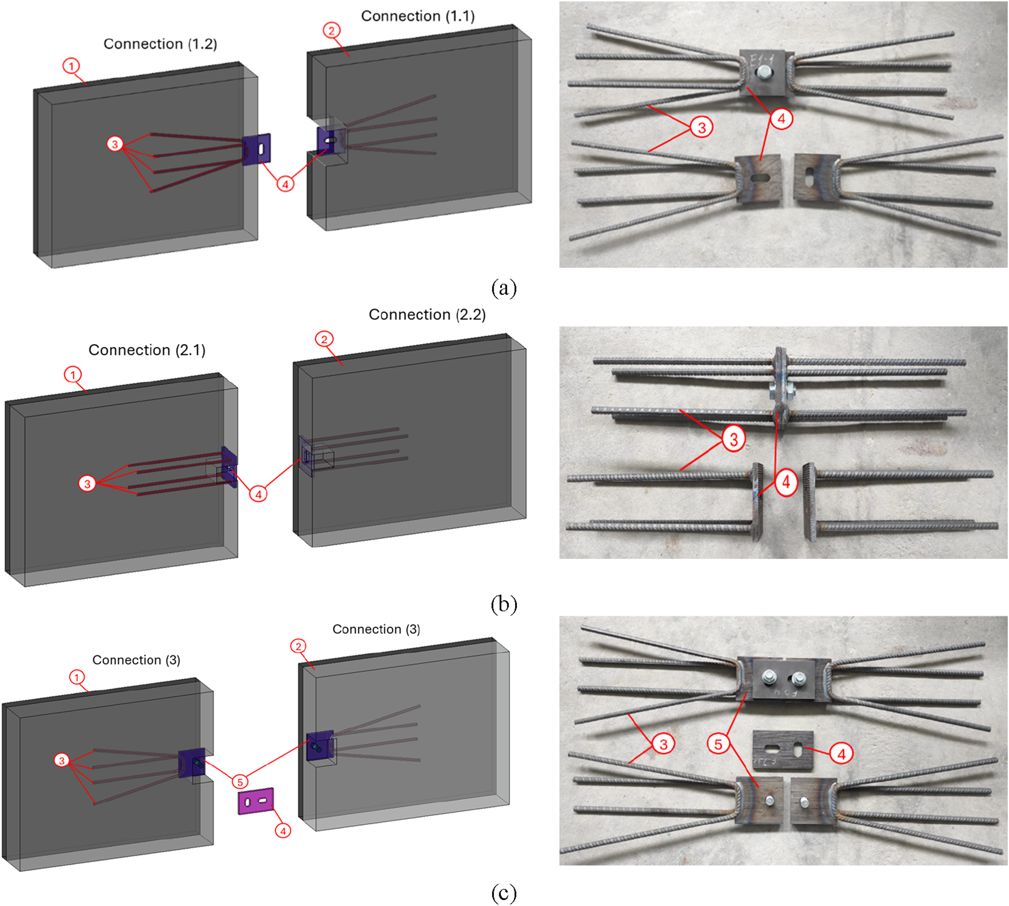
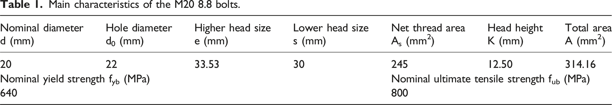
To transfer the stresses between the connection and the precast wall, 4∅12 mm of S500 steel rebars were welded to the steel plates with two fillet welds, and anchored to the LCLWAC layer with a length, Lbd, of 400 mm. This anchorage system was designed in terms of reinforcement ratio, anchorage length, and configuration to ensure a high concrete-to-steel contact area and sufficient anchorage capacity to exceed the shear strength of the bolt. The steel plates were designed with oval holes in orthogonal directions to comply with the tolerances required during the on-site assemblage, allowing higher flexibility in assembly. These tolerances have been defined according to EN 13369 (2023) and the proposed connections were designed following the Eurocode 3-1-8 (2005) recommendations. The steel plate was designed with 12 mm thickness, so that its crushing strength would exceed the shear strength of the bolt. Some plates have indented surfaces, with dimensions around the 2.5 mm pitch, to increase the friction component between the two plates (Figure 2(b)). The Connection-1 is shown in Figures 3(a) and 4(a). This connection is not symmetrical, since one side has an opening for the bolt installation (Connection-1.1) and, on the other side, the steel plate is outside the wall (Connection-1.2). Also, Connection 1.2 is not centred on the wall cross-section, to allow overlapping and assembly with Connection 1.1. Special attention is required during the production stage, to ensure that the plates on both sides completely overlap, especially for the indented plates, and to guarantee the correct alignment of the two walls. Connection-2 is adapted from Guo et al. (2019) (Figures 3(b) and 4(b)) and is similar on both sides, with a variation in the ovalized hole orientation. The plates are embedded in the LCLWAC, with an opening for the bolt installation, on both sides. No indented plates were used for Connection-2 in this study, because this connection does not depend on friction between the plates, when subjected to tensile stresses. Connection 3 (Figures 3(c) and 4(c)) differs from connections 1 and 2 because the bolts are already welded to the plate and a third free plate is actually used to connect both sides. The two sides of this connection are similar, and the free steel plate also has two ovalized holes in perpendicular directions. This free plate makes walls’ assembling easier, compared to Connection 1 and 2, and ensures the correct alignment of the two connected walls. Connections 1 and 3, due to their configuration, have a different distribution of the four anchor rebars, compared to Connection-2, to prevent the overlapping of the tensile concrete mobilized surrounding to the rebars. Detail of the steel dry-connections: (a) Connection-1; (b) Connection-2; and (c) Connection-3 (units in millimetres).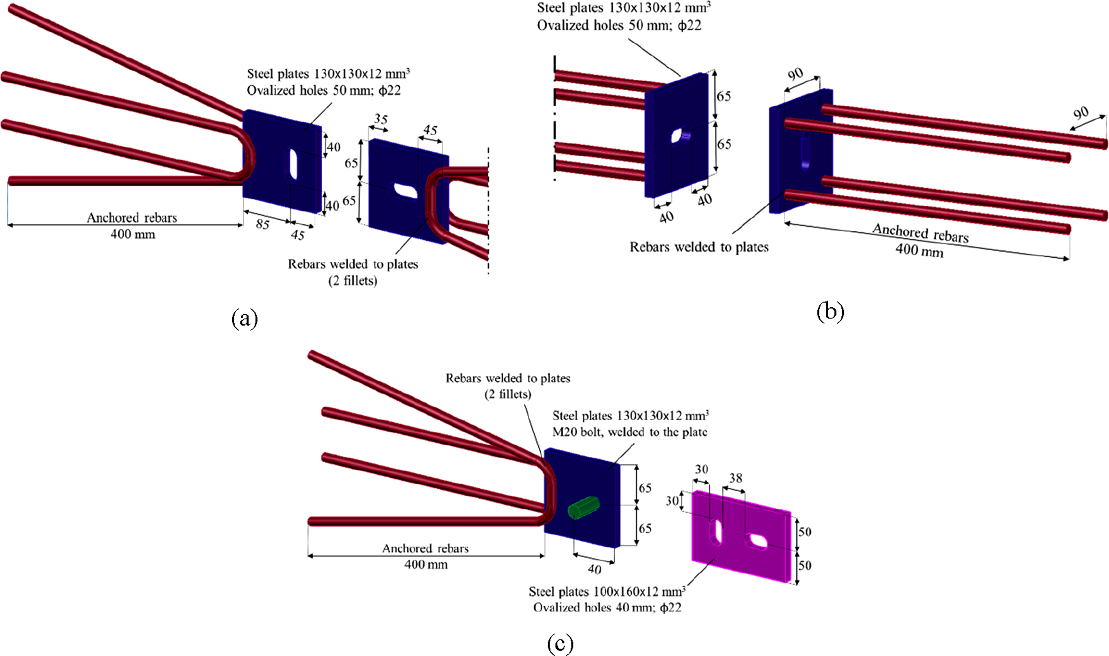
The installation process is similar for all connections, summarized as follows: (i) transporting the precast walls to the site; (ii) positioning the walls under the previously executed foundation slab; (iii) levelling the walls and connecting them to the slab and laterally to other walls, using the bolts; (iv) overlapping the floor slab in the grooves left in the LCLWAC layer; and bolting it to the walls below; and (v) repeating the processes to complete the installation of the structure. After the assembly, the exposed steel elements should be protected against corrosion and fire with an accessible element that can be removed, if necessary (e.g. for maintenance operations or for disassembly and deconstruction of the structure or parts), to avoid degradation and durability problems. These elements were not considered in the experimental study.
The connections were designed to avoid the following failure modes: (a) slippage of the anchor rebars; (b) reinforcement yielding; (c) steel plate’s bending/deformation; (d) concrete crushing; and (e) slippage at the concrete-to concrete interface. In this way, the failure should occur due to the shearing of the bolt.
Experimental program
To investigate the behaviour under tensile loads, mainly maximum strength and the force-displacement curves of the proposed bolt connections, monotonic tensile tests were conducted. Next the adopted and the test protocol are described in detail.
Concrete properties and specimens’ production
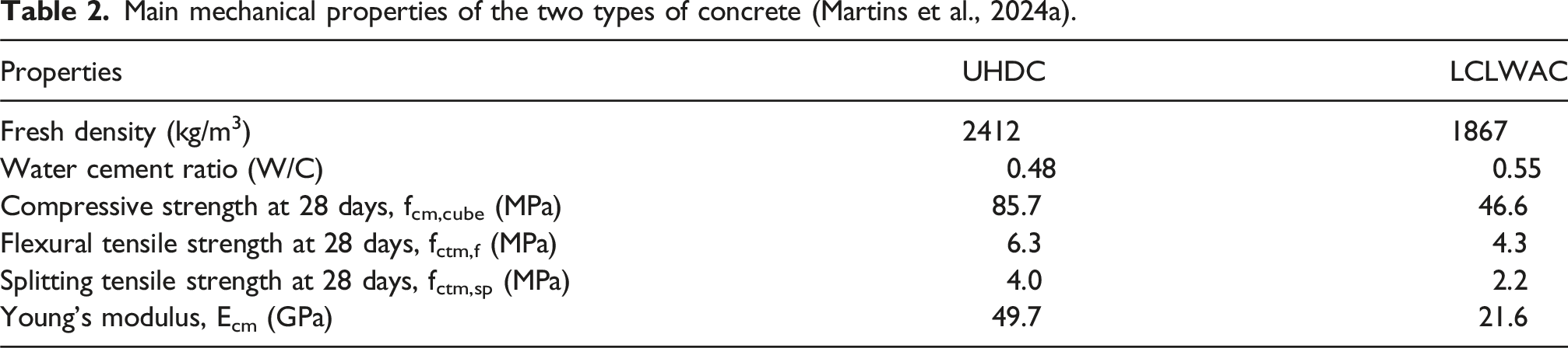
Main mechanical properties of the two types of concrete (Martins et al., 2024a).
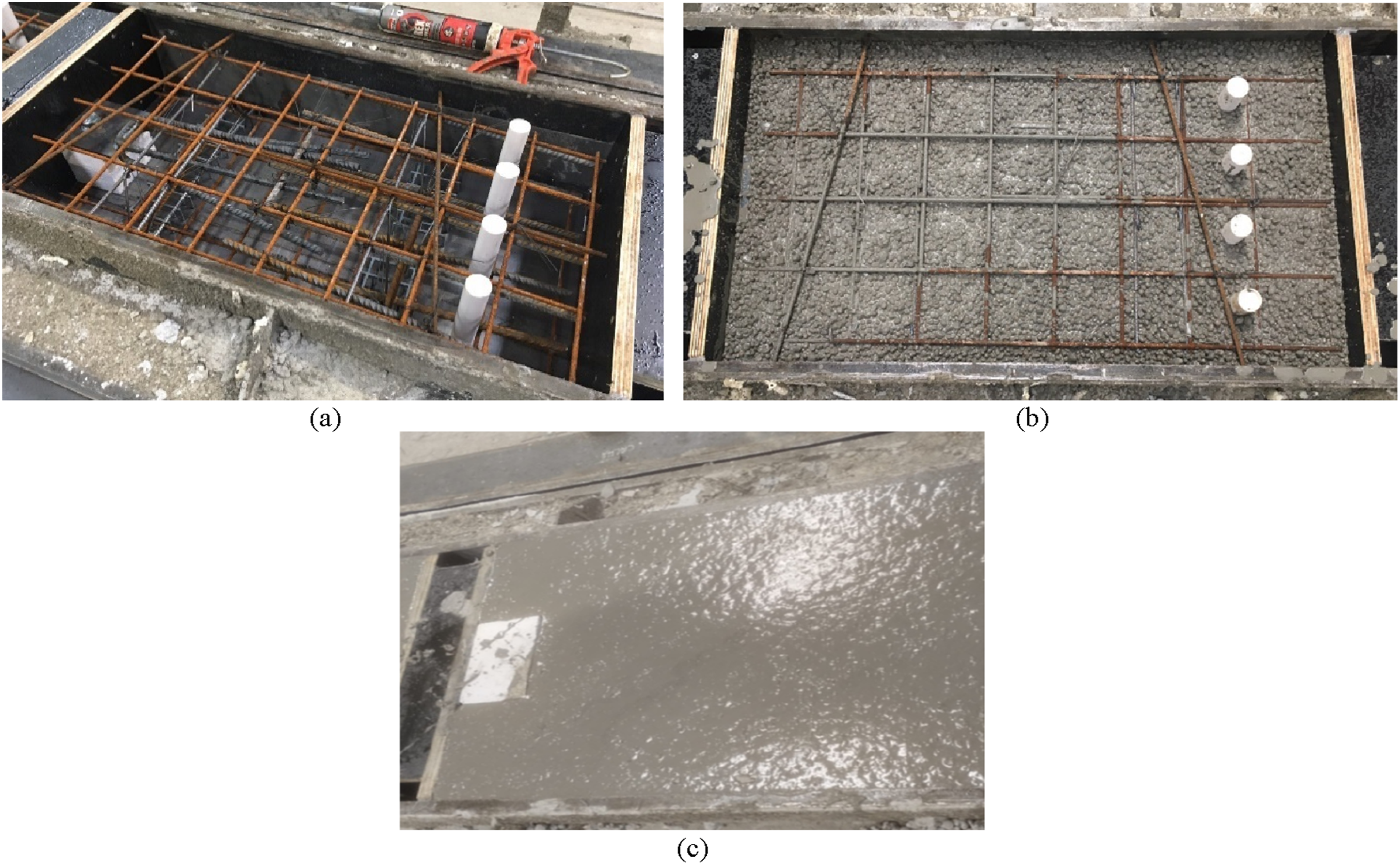
For the experimental campaign, it should be noted that it was not necessary to test an entire wall connected to another wall, i.e. only the wall region surrounding the connection was tested. The specimens had the following dimensions: 900 mm in length, 500 mm wide, each with a UHDC layer with 50 mm of thickness and an LCLWAC layer with 150 mm thickness (Figure 5). The specimen dimensions were defined to accurately represent the interaction between the connection and the surrounding concrete, while minimizing the size of the elements to reduce production effort. Both layers were reinforced with an A500 ER steel rebars mesh Ø6//0.10 m (As = 2.83 cm2/m). The layers were connected by three-dimensional steel trusses with a height of 120 mm, using a smooth left-as-cast interface, which based on previous studies was shown to provide sufficient strength while simultaneously simplifying the production process (Martins et al., 2024b). The specimens had 4 holes in the bottom, along the cross-section, to attach the specimens to a reaction steel frame and to support the tensile force applied to the connection. Also, to prevent premature failure outside the connection region, the bottom of the specimens was reinforced with Ø12//0.10 m. To assure the reliability of the results obtained, two equal wall’s specimens were produced and tested. Figure 5 shows the geometry and reinforcement details for the specimens used to test the connections. Note that for Connection-1, both sides of the connection are shown, due to its non-symmetry, unlike Connection 2 and 3. Each specimen was identified according to the following rules: the type of connection (1, 2 or 3) and the roughness of the steel plate (smooth, “S” or indented, “I”). The specimens were produced in two phases: (i) the formwork was prepared to cast the LCLWAC layer, incorporating the steel reinforcements, the steel connection and the negatives for the installation of the bolts. After casting, the layer was consolidated on a vibration table; and (ii) the addition of the UHDC, approximately 4 hours later (Figure 6). This order of casting is considered to be the best approach, since the UHDC is the strongest concrete and requires less vibration, which could cause cracking in the LCLWAC, already cast inside the formwork. After 24 hours, the specimens were demoulded and stored at 18°C ± 3°C and 65% ± 10% RH. Geometry and reinforcement details of the specimens (dimensions in mm). Legend: (1) reinforcement (tensile test) Ø12//0.10; (2) negatives Ø22; (3) metallic truss; (4) steel connection - anchored rebars 4Ø12); (5) steel connection – plate with bolt’ hole; (6) LCLWAC layer; (7) UHDC layer; (8) layer’ reinforced mesh Ø6//0.10; (9) bolt installation; 10) steel connection – plate with welded M20 bolt. Specimens’ production: (a) formwork with reinforcement and negatives; (b) LCLWAC casting; and (c) UHDC casting.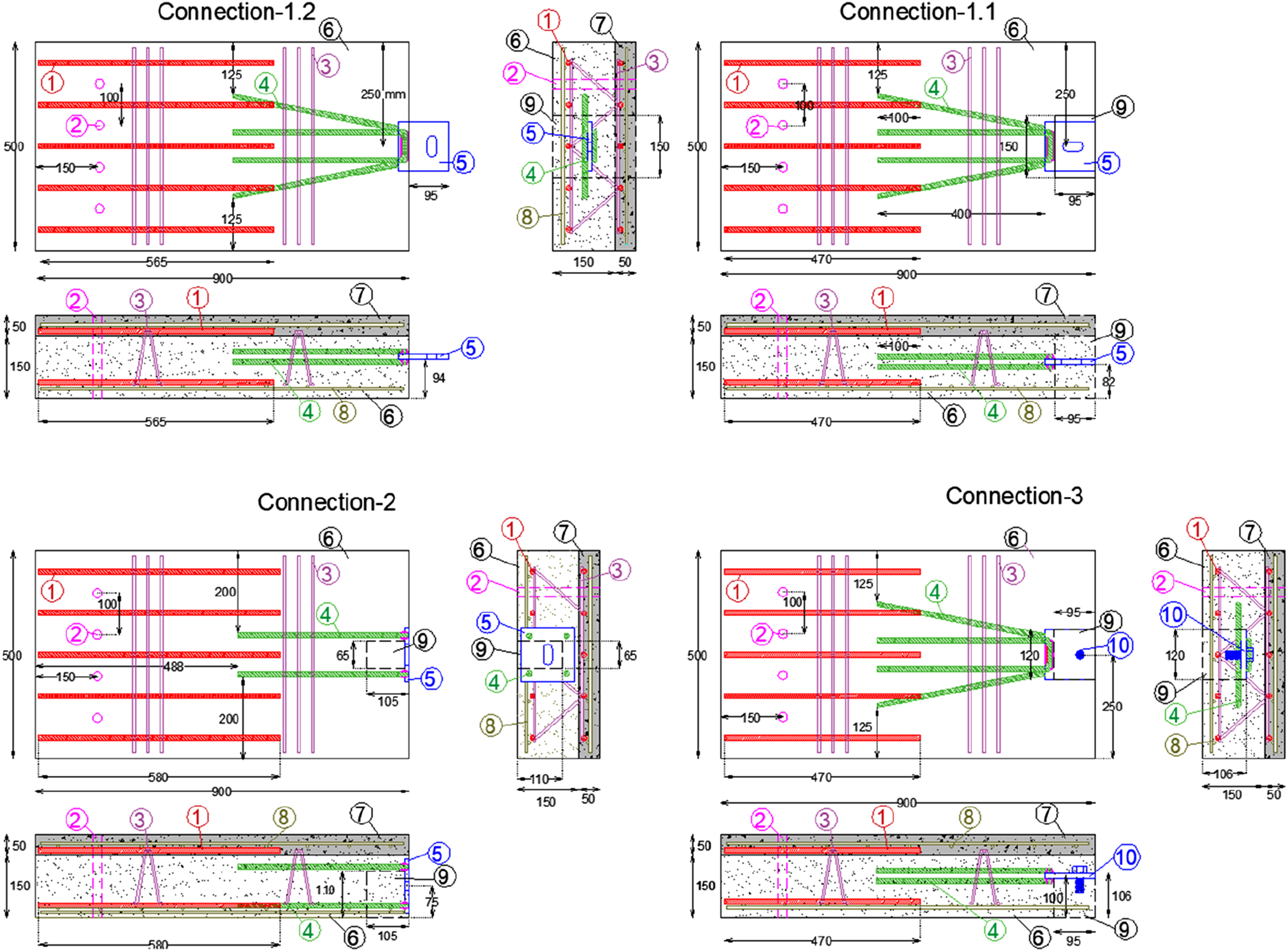
Test protocol
The tests were performed 28 days after the production of the specimens, applying a monotonic axial tensile loading, with a displacement control at a rate of 0.01 mm/s. To perform the tensile tests, each specimen was positioned over a steel beam and fixed to the steel reaction frame using 4Ø20 rebars crossing the 4 holes, as shown in Figure 7. The load was vertically applied until failure, using a hydraulic servo-actuator, which was linked to the connection. All bolts were tightened manually using the same procedure and by the same operator to ensure consistent tightening across all tests. Since the bolts were tightened manually without torque measurement, the applied torque and the resulting bolt preload were neither controlled nor quantified. The displacements were measured using four linear variable differential transformers (LVDTs): (i) two LVDTs were installed vertically at the top of the wall (LVDT1 and LVDT2); and (ii) two LVDTs at the bottom of the specimen (LVDT3 and LVDT4) see, Figure 7. The data was recorded with a frequency of 1 Hz. Monotonic tensile test and instrumentation. Key: (A) Metallic frame; (B) Actuator with load cell; (C) Rotation-free support (actuator); (D) Rotation-free support (steel head for tensile action); (E) Vertical LVDT; (F) Specimen; (G) Reaction slab; (H) Metallic beam; (I) steel box (specimen anchorage).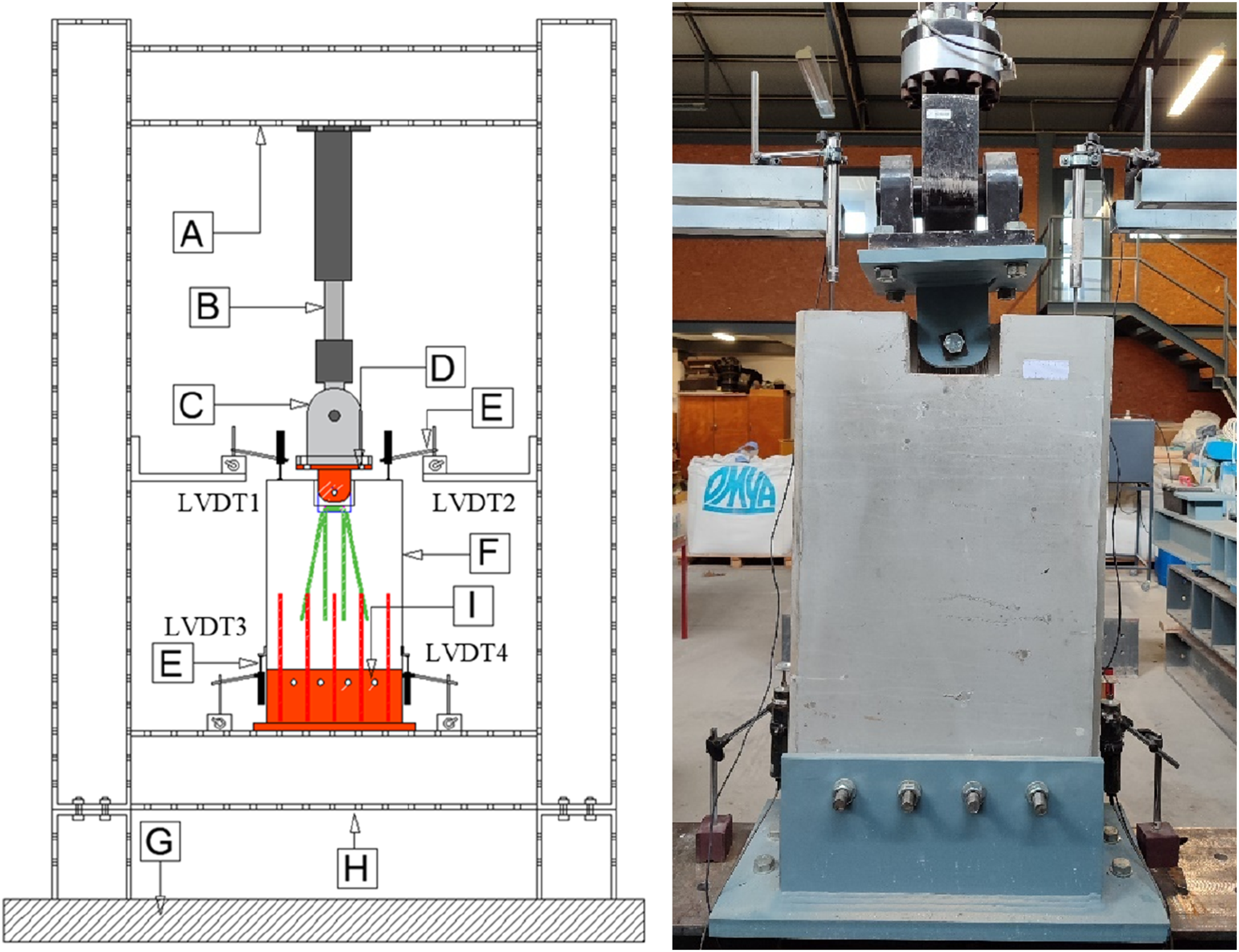
Experimental results and discussion
Connections capacity
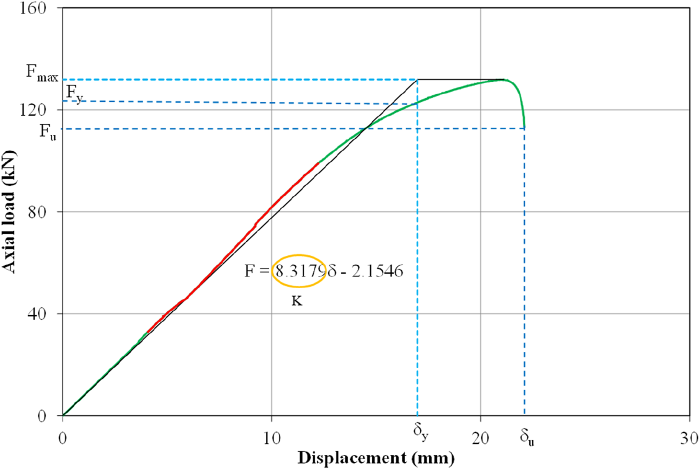
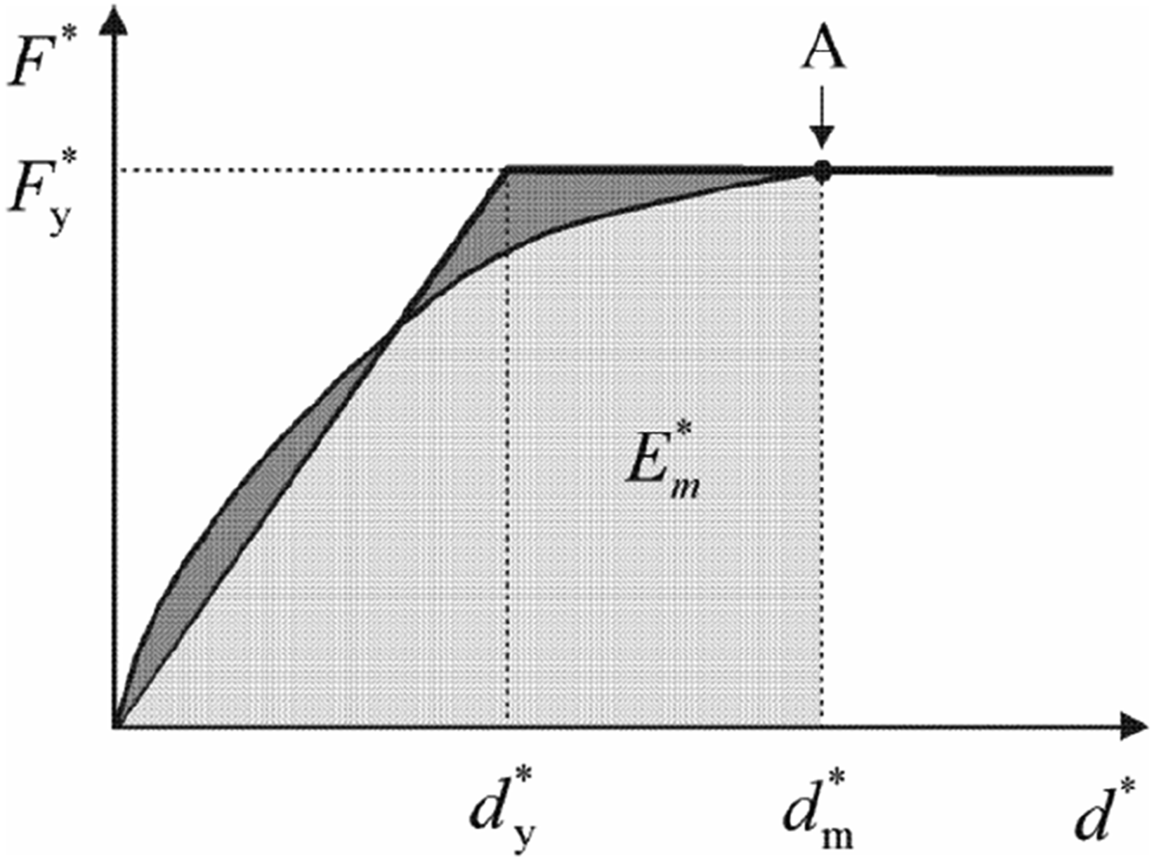
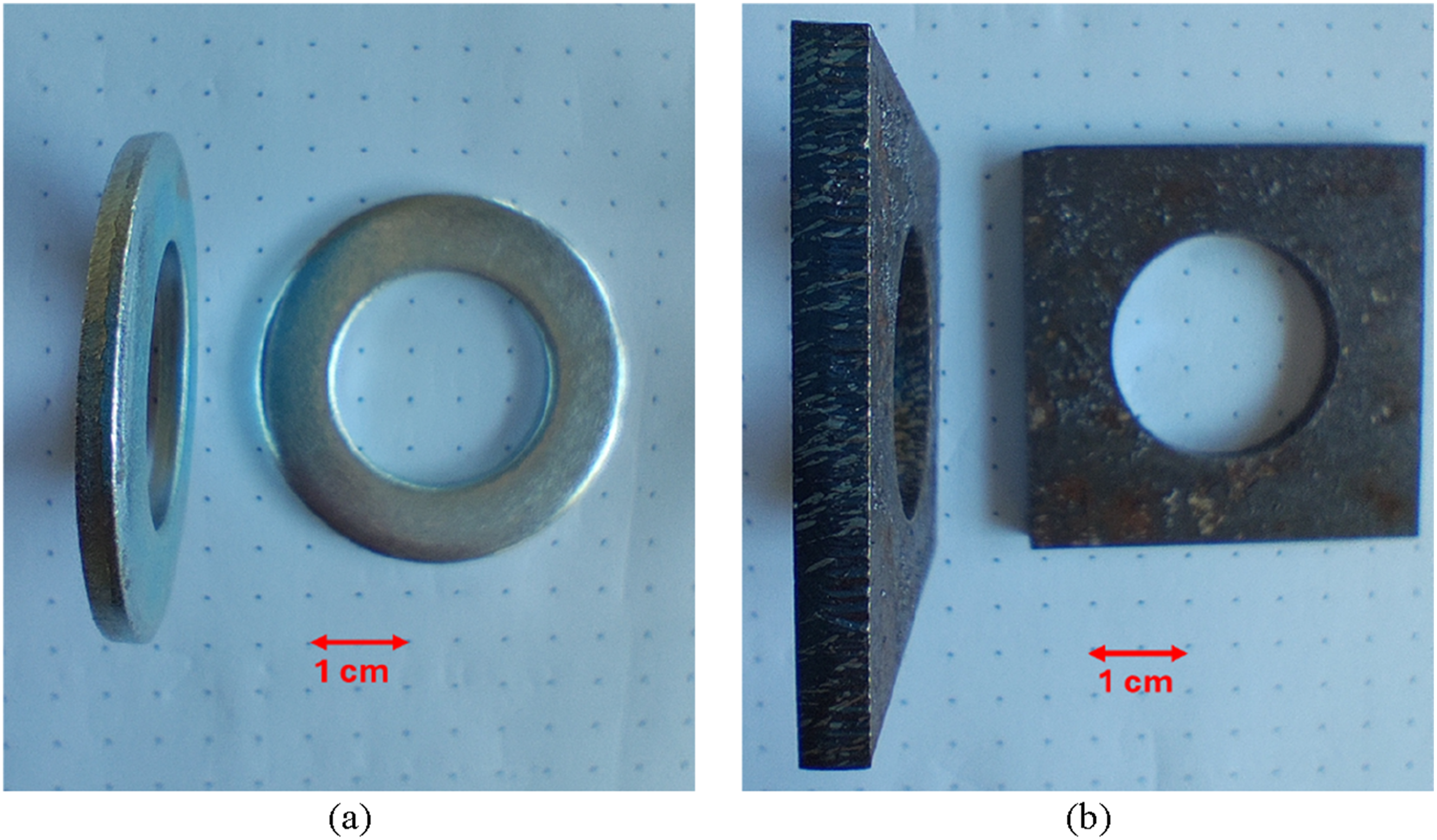
The performance of the connections was evaluated through their axial capacity and the associated deformation, computed by the difference between the actuator’s displacement and the average of the two top LVDT1 and LVDT2. These curves allow to characterize several relevant parameters related to the structural behaviour of the dry connections, namely: the stiffness, the yielding load and corresponding displacement, the peak load and corresponding displacement and the post-peak behaviour. The stiffness, K, was determined through the slope of the line defined by the points between 0.3 and 0.7 of the maximum force, Fmax (Figure 8). The yield displacement, δy, and yield force, Fy, were computed according to the proposal of Annex B of the Eurocode 8, (2009). This approach assumes an idealized force-displacement relation, that allows computing the yielding coordinate of the curve (Figure 9 and Equation (1)). The displacement ductility index, μδ was used to quantify the ductility of the specimens, and it corresponds to the ratio between the ultimate displacement (displacement at the end of the test) and the yield displacement (Figure 10). Also, the ultimate values, at the end of tests, were analysed: (i) ultimate force Fu; and (ii) ultimate displacement, δu. Figure 11 shows the axial load-displacement of all specimens tested and Table 3 shows the analysed parameters. Example of computing the analysed parameters – specimen T1.1_S. Determination of the idealized elastic-plastic force displacement relation (Eurocode 8, 2009) (Key: A – plastic mechanism; Axial load-displacement relation: (a) Connection-1; (b) Connection-2; and (c) Connection-3. Steel washer: (a) Connection-2.1; and (b) Connection-2.2. Response parameters of the specimens determined experimentally.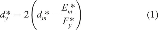
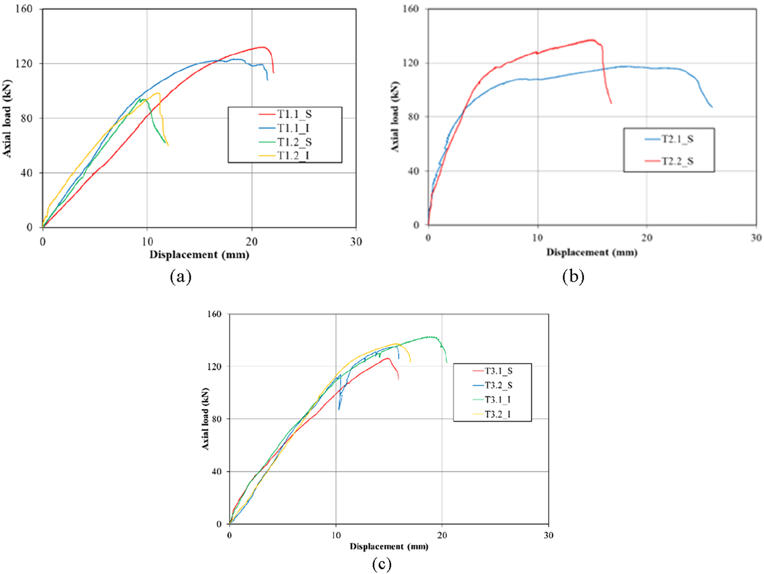
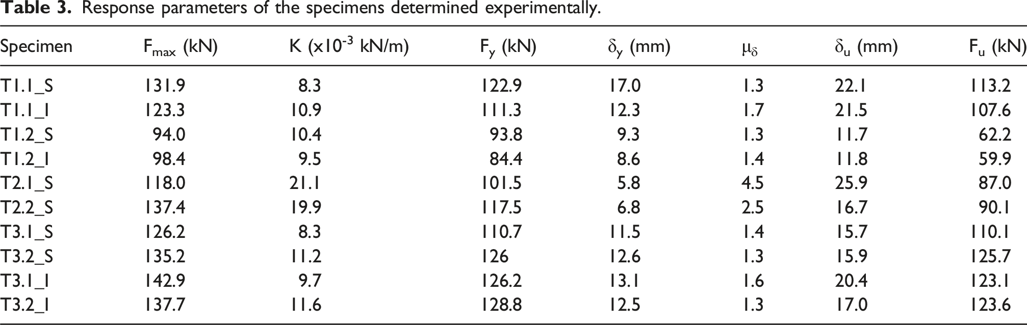
Regarding Connection-1, it was observed an important variation in the maximum strength between the two sides. The Connection-1.1, with the steel connection inside perimeter of the wall (Figure 3), shows a higher strength capacity, circa 33 %, when compared with Connection-1.2. This is because, the failure of Connection-1.1 occurred due to the shearing of the bolt (as desired), with no evidence of concrete cracking, while in Connection-1.2, the failure occurred due to separation along the LCLWAC-UHDC interface, since, in this configuration, the connection is closer to the interface. This means that the capacity of Connection-1 is limited by the weakest side (Connection-1.2). Special attention should be given during the walls’ production to guarantee an adequate bond at the LCLWAC-UHDC interface, namely by increasing the roughness of the surface between the concretes (Martins et al., 2024b). The indented plates, used to increase the friction coefficient, did not significantly affect the strength and stiffness of the connection, compared to connections with smooth plates.
Despite the symmetry of Connection-2 (it is equal on both sides), the results were slightly different. During the test of Connection-2.1, an excessive deformation of the steel washers was observed, which affected the maximum strength. To mitigate this problem, the steel washers in Connection-2.2 (specimen 2) were updated to provide a larger contact area with the plate and to have higher thickness (Figure 11). This correction results in an increase in yield and maximum strength, of circa 15 %, with respect to Connection-2.1. However, because the deformation of the plate is reduced, the ductility was reduced to almost half the one observed in Connection-2.1.
In Connection-3, identical behaviour was observed on the four tested specimens (two with smooth plate and two with indented plate). In this case, the effect of the roughness of the plates was clear, the connection with indented plates supported higher loads, circa 8 % than the smooth plates. The ductility index varied between 1.3 and 1.6 and yielding occurred at about 12.4 mm in all four specimens.
Damage assessment and failure mode
To further investigate the performance of the specimens, the deformations observed in the concrete specimens were analysed, using the relation between the average of the two vertical LVDTs positioned at the top and the average of the two LVDTs at the bottom of the specimens. Figure 12 shows the displacements for Connection-3, which are representative of the behaviour observed also in tests for the other two types of connection. After the initial gap adjustments, the deformation at the top became higher than the one measured at the bottom. The points marked on the curves represent the initial cracks of concrete (for a load approximately 75% of Fmax). Average LVDTs top displacement – average LVDTs bottom displacement ratio (Connection-3).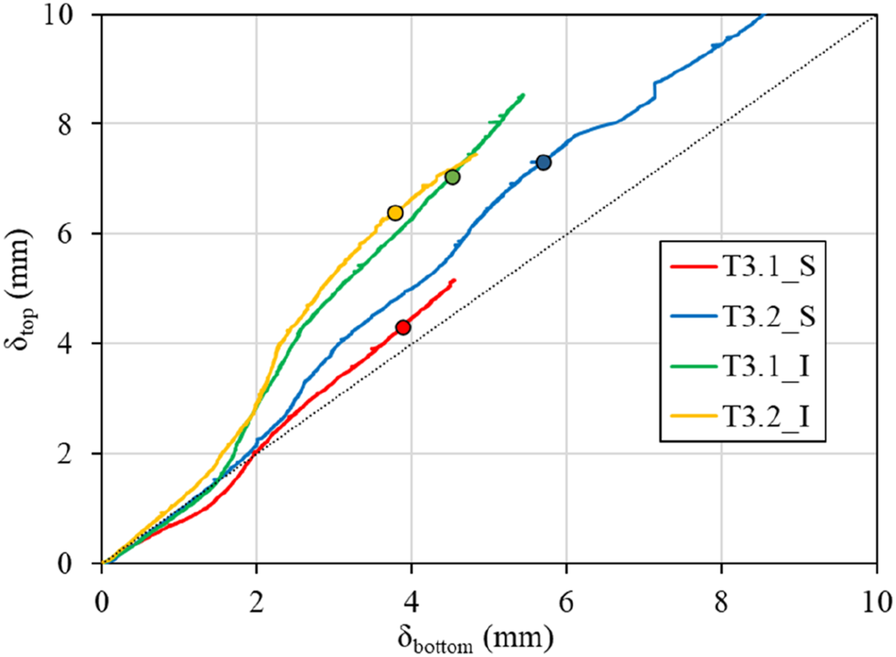
Part of the deformations observed in the concrete region results from the concrete itself and from the localized deformations at the interface between the steel plates and the concrete, which defines the anchorage region.
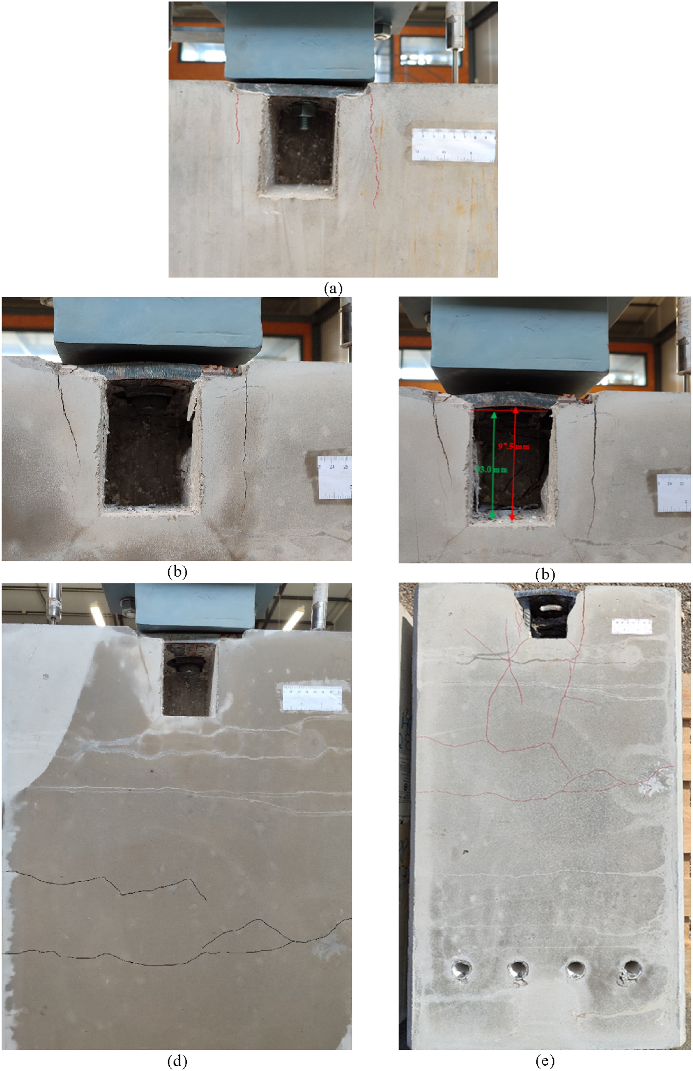
The effectiveness of the design anchor regions can be assessed through the crack pattern, and its evolution along the test. Assuming that for Service Limit States, the load corresponds to 75% of Ultimate Limit States, and thus analysing the specimens when the load ranged between 50 and 75% of Fmax, it can be stated that, under service conditions, only microcracking, lower than 0.2 mm width, was observed. More specifically, In Connection-1.2 and Connection-3, microcracks were observed in the UHDC-LCLWAC interface (Figures 13(a) and 15(a), respectively). This does not occur in Connection 2 because the connection itself, namely the arrangement of the anchor rebars, contributes to increasing the strength between the two concrete layers. In this case, contrary to the former, microcracks appeared near the opening, aligned with the position of the anchor rebars (Figure 13(a)). Yet, this was not observed in Connection-2.2, probably due to the changes performed on the steel washer, which reduced the deformation of the late and consequently, of the steel bars attached to it. Connection-1 - Crack pattern: (a) Service conditions (75% Fmax); (b) Connection-1.2 at failure; (c) Connection-1.1 at failure. Connection-2 - Crack pattern: (a) at service conditions (75% Fmax); (b) vertical cracking in the opening at Fmax (0.7 mm crack width); (c) bending of the steel plate at the end; (d) horizontal cracking at F = 110 kN (80% Fmax); (e) crack pattern at the end.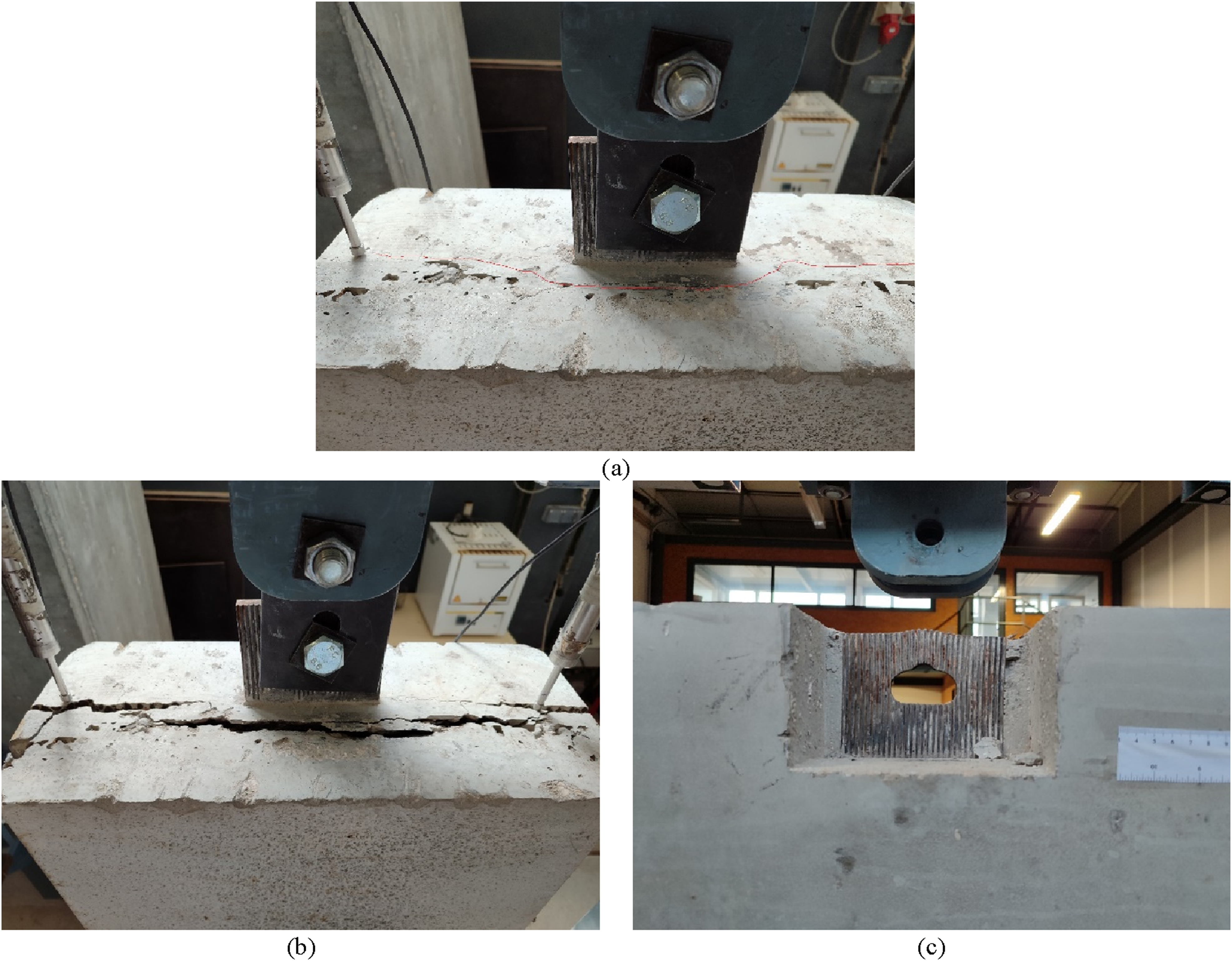
Regarding the performance near failure, the crack pattern of Connection-1.2 progressively evolved along the UHDC-LCLWAC interface, with the slippage of the anchor rebars and consequently of the steel plate (Figure 13(b)). In Connection-1.1, only the deformation of the steel plate, caused by the bolt, was observed (12c).
The behaviour of Connection-2 can be described by the following sequence: (i) development of vertical cracks near the opening (Figure 14(b)); (ii) development of horizontal cracks in the section with transition of reinforcement associated with the connection and the one used to near the anchorage region of the specimen (Figure 14(d)); (iii) bending of the steel plate at higher load levels (Figure 14(c)); and (iv) detachment of concrete around the opening (Figure 14(e)). At failure, there is significant damage around the opening, due to the arrangement of the anchor rebars that is too close to the edge of the opening. This behaviour is more pronounced in Connection 2.1, where the steel plate experienced greater deformations, crushing the concrete under the plate.
Finally, and like Connection-1.2, the crack pattern in Connection-3 is mainly characterized by the presence of the cracks at the interface between the UHDC and LCLWAC. Cracking occurred at the top of the wall due to tensile stresses transmitted by the connection, approximately at 75% Fmax (Figure 15(a)), and propagated from the plate to the edge of concrete-to-concrete interface (Figure 15(b) and (c)). Nonetheless, failure occurred due to the shearing of the bolt. Connection-3 - crack pattern: (a) at service conditions (75% Fmax); (b) at failure (specimen’s top); (c) at failure (specimen’s side).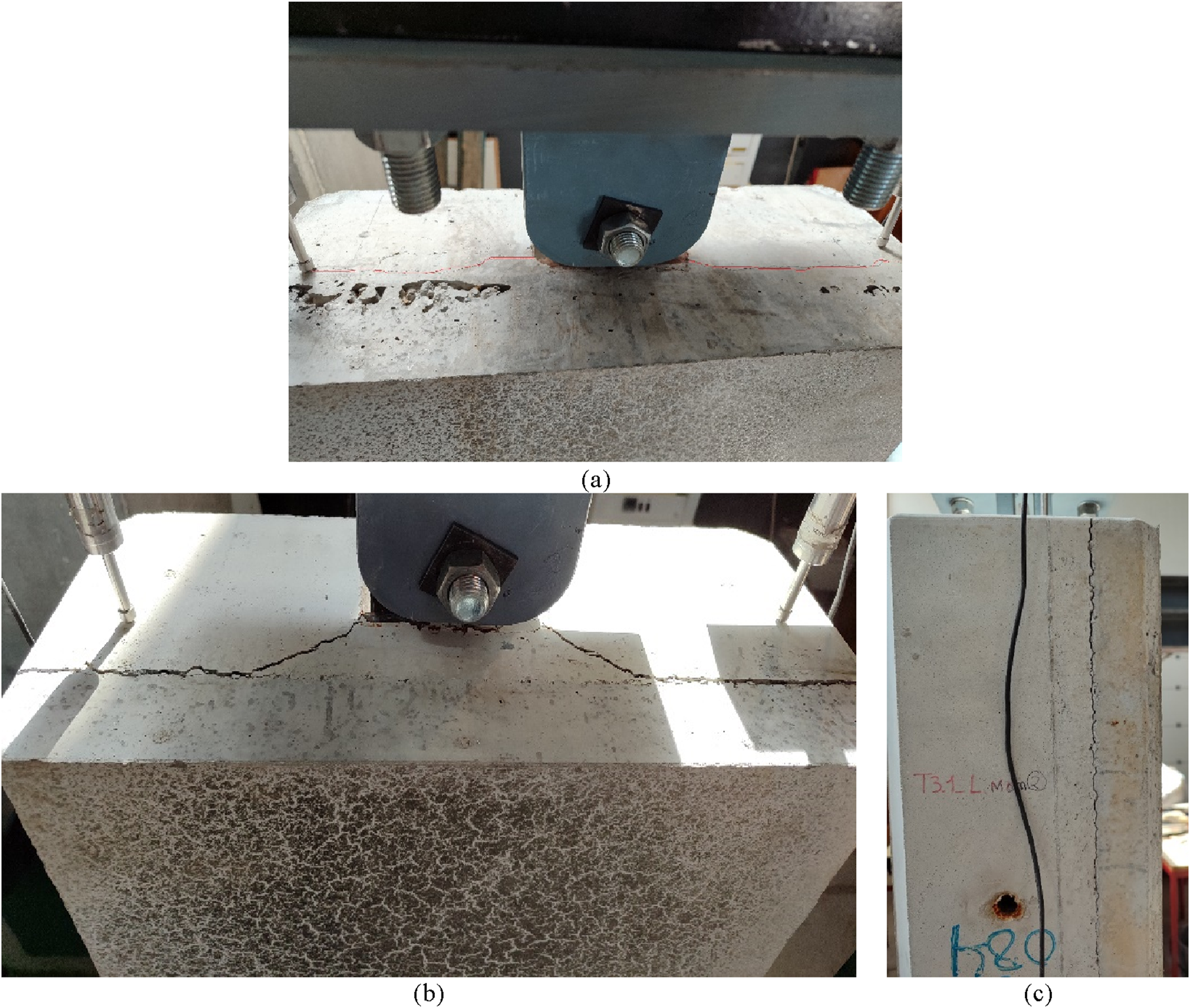
Comparison of the different connections
The comparison of the three connections shows that Connection-3, namely the one with indented plates (T3_I), has the better structural performance. Figure 16 shows the normalization of the most relevant considered parameters, obtained by the ratio between the mean experimental values from Connection 1, 2 and 3_S (identified as Ti) and the corresponding values measured in Connection-3_I (identified as T3_I). For example, Figure 16(a) shows the ratio between the yield load of Connection 1, 2 and 3 (smooth plates), Fy,Ti, and the yield value of Connection-3 with indented plates, Fy,T3_I. In terms of strength, Connection-3_I present a better performance, with a maximum and yield strength approximately 30% and 10% higher than those of Connection 1 and 2, respectively. Connection 2 and 3 proved to have higher strength capacity than Connection-1, which is conditioned by the weakest side (lower strength capacity), Connection-1.2. Consequently, the yield load is also lower, between 20% and 30%, compared to Connections 2 and 3. On the other hand, Connection-2 exhibits a higher initial stiffness, circa 2 times higher than those of Connections 1 and 3 and a more ductile behaviour, 50% higher, compared to the other two connections. This is due to the configuration of the connection, where the bolt is in tension and causes the connection’s steel plate to bend. Connections should preferably behave in a ductile manner, therefore, from these results Connection-2 seems to have the best performance regarding this parameter (fib (Task Group 6.2), 2008). Comparison of different response parameters with respect to Connection-3_I: (a) maximum and yield load; (b) ultimate and yield displacement; (c) stiffness; and (d) displacement ductility index.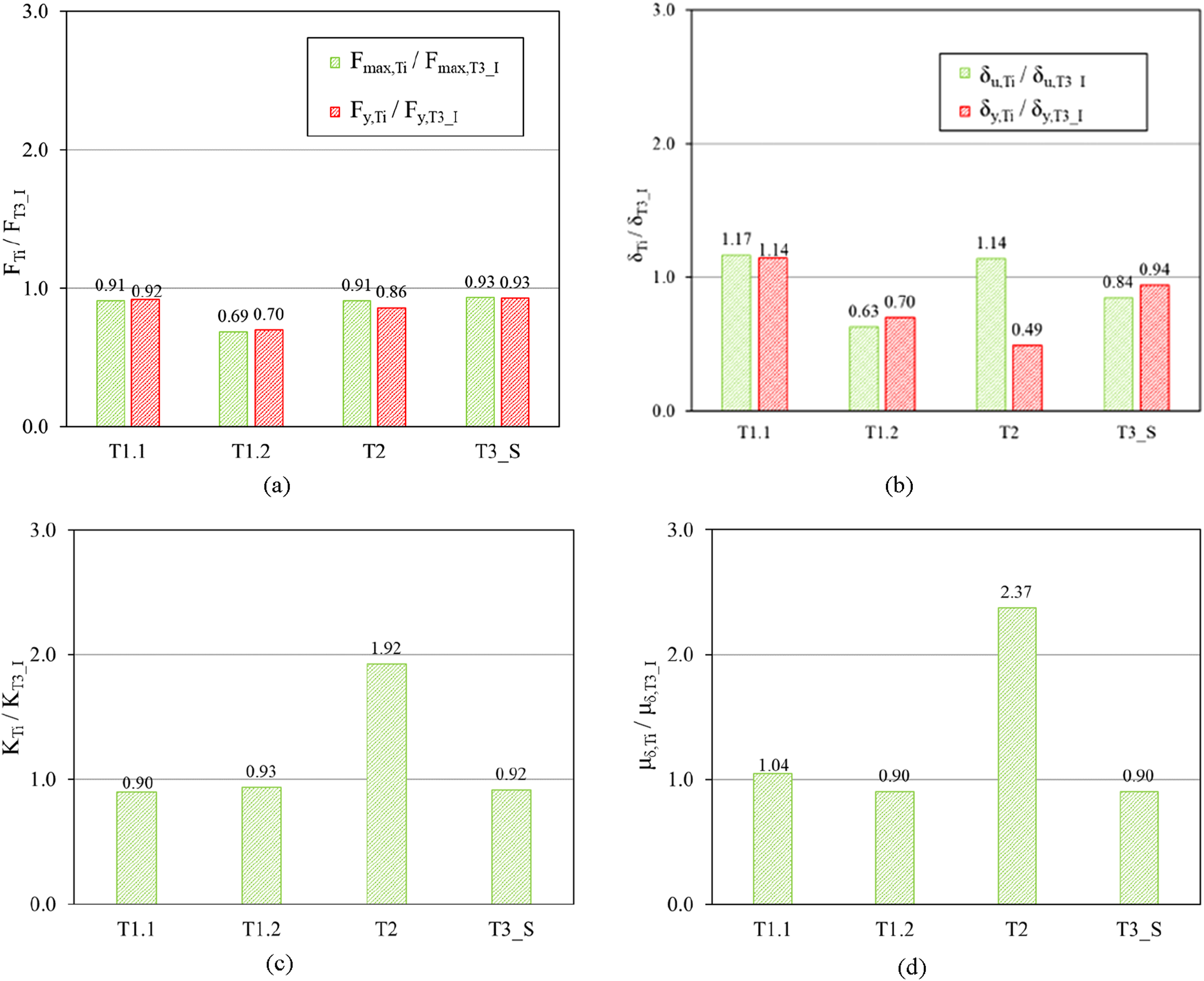
In terms of damage assessment in the anchorage region, the configuration of the steel reinforcement used in the Connections 1 and 3, with a sufficient concrete cover and anchorage length, creates a higher contact surface with the surrounding concrete and, hence, reduces concrete damage. Consequently, these two connections show less cracking in the anchorage region, compared to Connection-2.
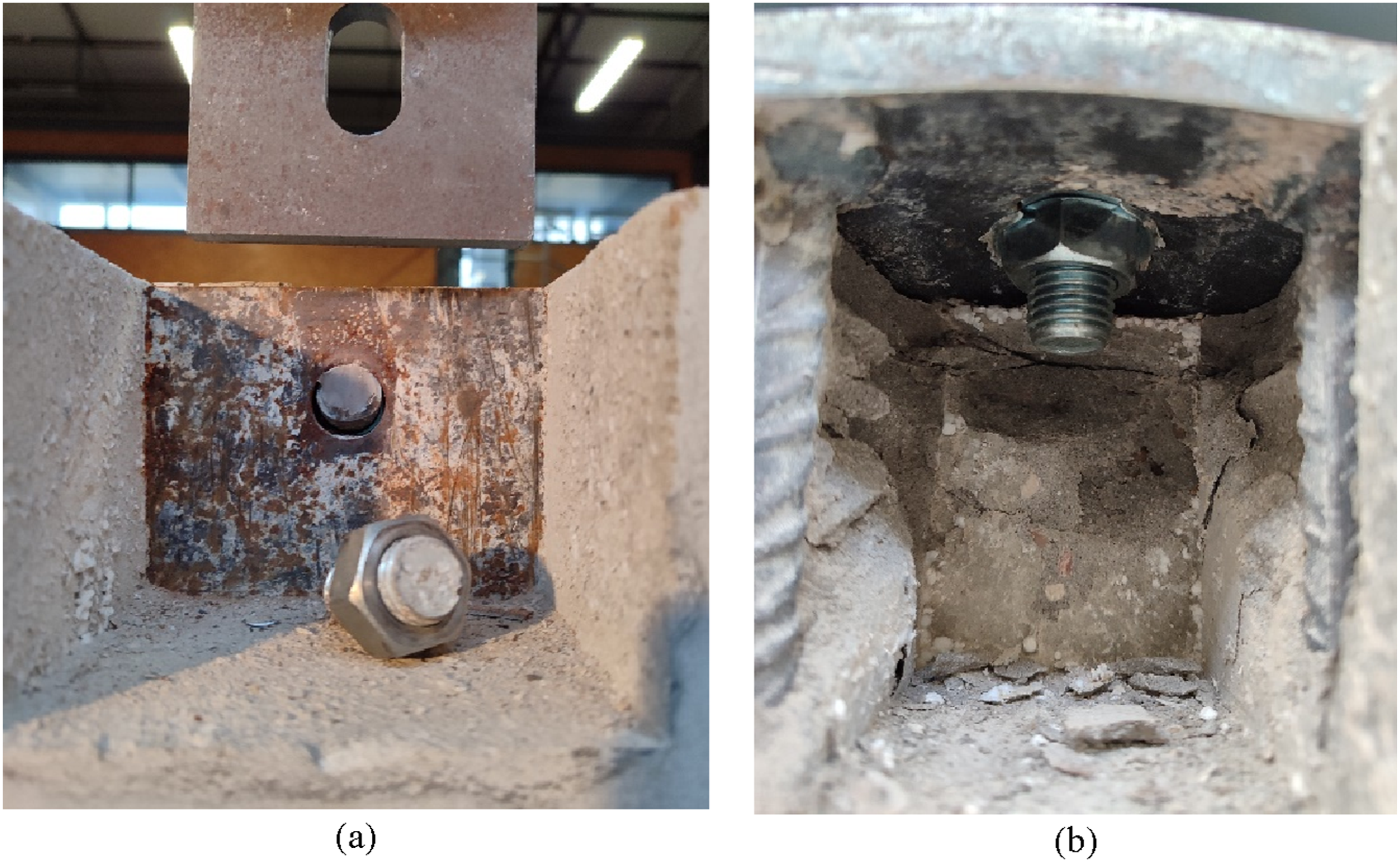
Figure 17 shows the ratio between the maximum load of each specimen and the design strength of the M20 8.8 bolt, according to Eurocode 3-1-8 (2005). The design tensile strength of the bolt, Ft,Rd, is 177 kN (Connection-2), and the design shear strength, Fv,Rd is 118 kN (Connection 1 and 3). The cases where the ratio is higher than 1 indicate that the maximum capacity is limited by the bolt failure, as seen in Connection-1.1 and Connection-3 (Figure 18(a)). On the other hand, in Connection-1.2 and Connection 2, the load capacity is conditioned by other factors, namely by cracking at the interface between the concrete layers and the excessive deformation of the steel plate, respectively (Figure 18(b)). Relation between experimental maximum load and design strength of the M20 8.8 bolt. Failure mode: (a) bolt shear failure (Connection 1.1 and 3); and (b) steel plate deformation (Connection-2).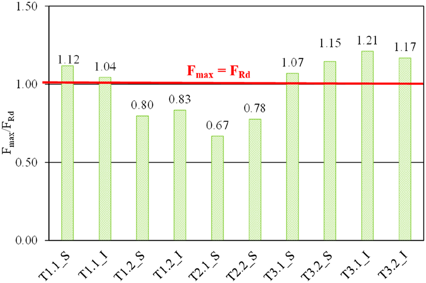
Conclusions
This paper is part of the development of a high-durability, eco-efficient and lightweight precast composite wall system for the construction of affordable buildings, that can be quickly assembled and disassembled. Three new dry-connections to be used in the innovative precast wall system are presented in this study: (i) Connection-1 has two non-symmetrical components (1.1 and 1.2) that must be overlapped and bolted; (ii) Connection-2 is symmetrical and has the plates perpendicular to the load direction; and (iii) Connection-3 is also symmetrical and, has bolts already welded to the plates and the connection is made using a third free plate. The plates of Connections 1 and 3 are in the same plane of the wall. To assess the behaviour of the connections under monotonic tensile loading, an experimental program was considered and carried out. Based on the results, the following conclusions can be drawn: • All three connections can properly transmit a concentrated tensile load to the concrete wall without generating wide cracks under service conditions (assumed as corresponding to loads between 50 and 75% of the maximum applied load). The cracks appeared for a load close to 75% of the maximum load and their width is lower than 0.2 mm, for the same load level; • The strength of Connection-1 is limited by the strength of Connection-1.2 and comparing with the other two connections (2 and 3), the strength capacity is about 30% lower. On Connection-1.1, the failure occurs by the bolt, while on Connection-1.2 occurs by the separation of the concrete layers, at 80% of the bolt maximum shear strength. Due to the configuration of Connection-1.2, the steel plate of this component is not centred with the wall, and it is located close to the interface between the two types of concrete. To avoid this problem, a careful control of both mixtures and the roughness of the substrate is necessary; • In Connection-2, the steel washers have a key role and should be stiff (wide and thick) due to the ovalized hole of the plates. Washers with small thickness exhibit high deformations, compromising the strength of the connection (the strength capacity is 20% lower). The Connection-2 shows more damage at the end of tests, compared to Connection 1 and 3, namely near the required opening for the bolt installation. The configuration of this connection bends the steel plate, creating high compressive stresses on concrete near the edge of the opening. To reduce the damages, it is necessary to increase the thickness and the dimension of the plate to increase the support area and to move the rebars away from the opening; • Connection-3 show less damage than the other two connections, at the end of the test. This connection is conditioned only by the shear strength of the bolt. Also, the roughness influence of the plates is clear in this connection, since the increase of the friction component increases the connection strength, close to 10%. Overall, the Connection-3 is the one with the better structural performance of the three connections developed and tested, when subjected to a tensile load. In terms of execution, Connection-3 is more advantageous because a third free plate is used, making it easier to assemble the panels with tolerances.
The results presented are exploratory, so it is recommended to carry out more tests to improve the statistical significance of the results. Future studies should include local strain measurements to enable a more rigorous validation of the stress states in the different components of the connection. However, the experimental carried out test confirmed that the different proposed connections have potential to be used in the suggested precast wall solution, to assemble faster and easier, with less workmanship. Nonetheless, some minor corrections and optimizations are also required to correct some pitfalls identified, as abovementioned.
Finally, complementary experimental studies have already been carried out on these three connections to access their performance under cyclic loads and under shear forces, in order to, consequently, validate their application and to expand the potential range of applications. The design of the connections ensures that the primary failure mode occurs through bolt, with other potential failure mechanisms, such as concrete crushing, rebar yielding, steel plate bending, or interface slippage, are effectively avoided. This controlled failure behavior, combined with the observed energy dissipation under cyclic loading, confirms the robustness and seismic reliability of the proposed connections.
In the future, the global behaviour of composite walls with connections will be studied, namely, to know how many connections are needed per wall, depending on the seismic zone of the building, allowing to define the connections design fastening. To accomplish this, a parametric study with numerical models has also been conducted. Also, the study of the fire response behaviour of the proposed walls and respective connections is also an important issue and is being analysed for future publication.
Footnotes
Acknowledgements
The authors acknowledge the support of FCT - Fundação para a Ciência e a Tecnologia, through both the PhD scholarship SFRH/BD/05254/2020, granted to the first author and the project UID/6438/2025, that finances the authors’ research center, CERIS - Civil Engineering Research and Innovation for Sustainability. This article is a result of the Innovation Pact “R2UTechnologies| modular systems” (C644876810-00000019) by “R2UTechnologies” Consortium, co-financed by NextGeneration EU, through the Incentive System “Agendas para a Inovação Empresarial” (“Agendas for Business Innovation”), within the Recovery and Resilience Plan (PRR). The authors are also grateful to Vigobloco – Pré-fabricados, S.A., for co-hosting this research study, together with CERIS, and the companies LECA, CIMPOR and CHRYSO, for their support.
Funding
The authors disclosed receipt of the following financial support for the research, authorship, and/or publication of this article: The support of FCT - Fundação para a Ciência e a Tecnologia, through both the PhD scholarship SFRH/BD/05254/2020, granted to the first author and the project UID/6438/2025, that finances the authors’ research center, CERIS - Civil Engineering Research and Innovation for Sustainability. This article is a result of the Innovation Pact “R2UTechnologies| modular systems” (C644876810-00000019) by “R2UTechnologies” Consortium, co-financed by NextGeneration EU, through the Incentive System “Agendas para a Inovação Empresarial” (“Agendas for Business Innovation”), within the Recovery and Resilience Plan (PRR). The authors are also grateful to Vigobloco – Pré-fabricados, S.A., for co-hosting this research study, together with CERIS, and the companies LECA, CIMPOR and CHRYSO, for their support.
Declaration of conflicting interests
The authors declared no potential conflicts of interest with respect to the research, authorship, and/or publication of this article.