
Abstract
Steel concrete composite structures are extensively adopted in construction practices owing to their attractive merits in structural behaviour, material employment and economic consideration etc. Steel concrete composite slim-floor beam system is an innovative, economical evolution from conventional composite system, it is used for multi-story high-rise buildings to increase storey effective net height. This paper presents a numerical simulation and analysis on the shear resistance of concrete dowel shear connector with reinforcing rebar for composite slim-floor beams. A finite element model was developed and validated against experimental results available from reference and good agreement achieved. A parametric study, covering important component parameters including concrete strength, diameter of concrete dowel and diameter of reinforcing rebar, was conducted to investigate the effect of these connector components on the structural behaviour of dowel shear connectors. The numerical simulation and analysis further highlighted the influence of connector components on the shear resistance and slip behavior of this type of shear connection adopted for composite slim-floor beams. Finally, a simple prediction method is proposed to calculate the shear resistance of dowel shear connector with reinforcing rebar. The simple prediction method may be used for design reference.
Keywords
Introduction
Steel concrete composite structure is a cost-effective construction system with competitive behaviors for multi-story buildings owing to the composite actions among different components. Being one of the important composite construction types, composite slim-floor beam is an innovative, economical evolution from conventional composite system. The key composite action of this type of composite beam is applied through the shear connectors between steel section and concrete slab. The feature of a typical shear connection in a composite slim-floor beam may be that the steel-section with holes in the web embedded in the concrete beam with slab, and the concrete passing through the holes in the web to form a shear dowel between steel beam and concrete beam/slab. In reinforcement concrete structures, steel rebar not only is used to resistant axial loads, but also can be used to promote the shear load resistance through the rebar dowel action (Ghayeb et al., 2020; Palieraki et al., 2021; Pejatovic and Muttoni, 2024; Preti et al., 2023; Xia et al., 2015). In slim-floor composite beams, considering the shear resistance of pure concrete dowel is limited, reinforcing rebar is usually embedded in the concrete dowel to increase the shear capacity of dowel (Chen and Limazie, 2017; Majdub et al., 2022). The shear transfer mechanism and shear resistance of this type of composite slim-floor beam is mainly dependent on the concrete dowels (with or without rebar) passing through the web of steel section, the internal force and resistance redistribution are complicated and have a complex superposition when the composite beam subjects to bending (Aggelopoulos et al., 2021; Chen and Limazie, 2017; Majdub et al., 2022), therefore, a better understanding of mechanism and strength of dowel shear connector between the concrete and steel beam is extremely important for the development of reliable design method of composite slim-floor beam system.
In the past decades, various shear connectors were developed and investigated (Pardeshi and Patil, 2021) for composite structures, however the dowel shear connector for slim-floor composite beam system was not extensively studied although some scholars carried limited investigation and proposed simplified methods for predicting shear resistance, the prediction accuracy is yet to be promoted and simpler formulas expected. Leonhardt et al. (1987) investigated the behaviour of the so-called Perfobond strip connector in down-stand beams and proposed a simplified calculation method for the shear connector strength which is used to determine the concrete dowel shear failure, in which the shear connector strength depending on the compressive area. Zapfe (2001) demonstrated that the longitudinal shear resistance of the composite beam is related to the concrete tensile strength and the strength of the reinforcing rebar in the dowel. Huo and D’Mello (2013) and Chen et al. (2015) proposed expressions to predict shear resistances, in which the resistance of the shear connector relates to the concrete compression strength, the concrete tensile strength and tensile strength of rebar passing through the concrete dowel. Chen and Limazie (2017) developed an improved calculation method to predict shear resistance based on their previous study. Braun et al. (2019) presented an expression to calculate the strength of the shear connector, which includes two main parts, or shear resistance from the concrete dowel and shear resistance from the reinforcing rebar. Aggelopoulos et al. (2021) proposed a simple calculation method to predict the shear resistance of dowel in the composite slim floor beam. The research shows that the diameter of the reinforcing rebar and the concrete strength have a significant effect in the ductility and failure mode of the shear connection in the composite slim-floor beam, and it is suggested that the concrete bearing on the edge of the steel web acts uniformly across the opening diameter, the concrete bearing strength has a significant increase due to the confinement of the flange of the steel section around the concrete dowel. Study on composite slim-floor beams using dowel shear connections was conducted by many researchers (Aggelopoulos et al., 2021; Ahmed and Tsavdaridis, 2019; Braun et al., 2015; Chen et al., 2015; Dai et al., 2020; Lam et al., 2015; Sheehan et al., 2019; University of Stuttgart et al., 2019), in which the importance and function of shear connections were asserted, the accuracy of shear connector resistance affect the composite beam design. Currently gap between research and engineering practice is still existing and there is no specific design guideline for this type of connections. Therefore further research to explore the effect of material, dimension of components to the performance of dowel shear connector is necessary to support the design of composite slim-floor systems.
As an important research approach to complement experimental study, finite element model has been extensively employed for parametric study in structural analysis, which not only may shorten research period, but also may reduce research cost. Currently only limited literatures on numerical modelling study found for dowel shear connectors used slim-floor composite beam. Limazie and Chen (2017) developed FE model and proposed simplified analytical method to assess resistance of dowel shear connectors, however discrepancy is evident. Hosseinpour et al. (2018) investigated the shear resistance of web opening shear connector by experiments and FE modeling but no reinforcing bar used for dowel shear connector. The research presented in this paper is to develop the finite element model and then carry out a parameter study covering different concrete strengths, concrete dowel diameters and reinforcing rebar diameters to complement and extend experimental results, finally to develop a simple calculation method to predict resistance of dowel shear connector with or without reinforcing bar.
FE model development and validation
Experimental study
To investigate the concrete dowel shear connectors adopted for composite slim-floor beams, a series of push-out tests was conducted by the University of Stuttgart et al. (2019). The aim is to explore the effect of constitutive components to the performance of shear connectors, which covered important component parameters including concrete strength (C25/30, C30/37 and C50/60), diameter of concrete dowel (or hole in the steel web: 40 mm and 80 mm) and reinforcing rebar through the dowel (without rebar, rebar diameter 12 mm, 16 mm and 20 mm). To avoid the influence of eccentric loading, symmetrical geometry of specimen was adopted and 5 shear connectors in each side of the specimen. All specimen tests were conducted and evaluated according to EN 1994-1-1. Annex B2.5. Figure 1 shows a typical push-out test set-up. Table 1 summarizes the component parameters of specimens and shear connector resistance and slip behavior obtained. In which Set up of shear connecter specimen push out test (University of Stuttgart et al., 2019). Summary of control parameters, characteristic loads and slips of shear connectors (University of Stuttgart et al., 2019). Load - slip relationships of 10 specimens tested (University of Stuttgart et al., 2019).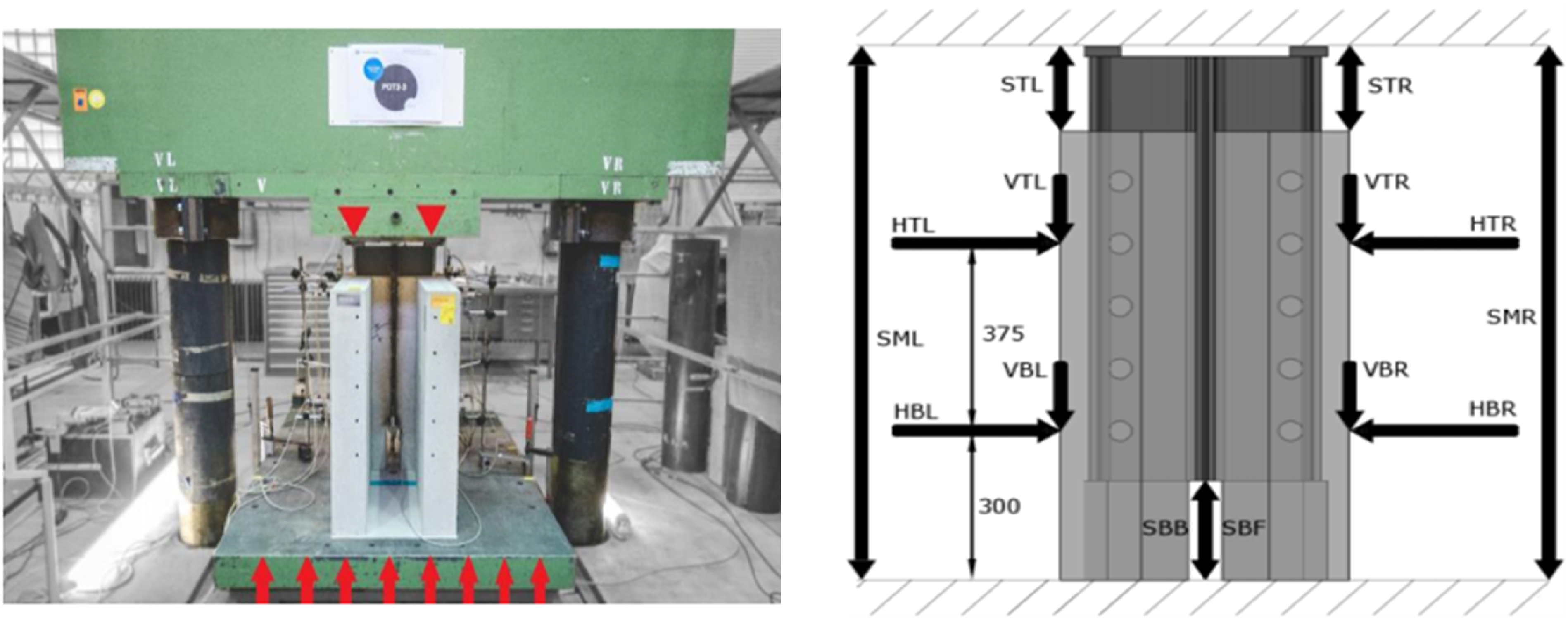
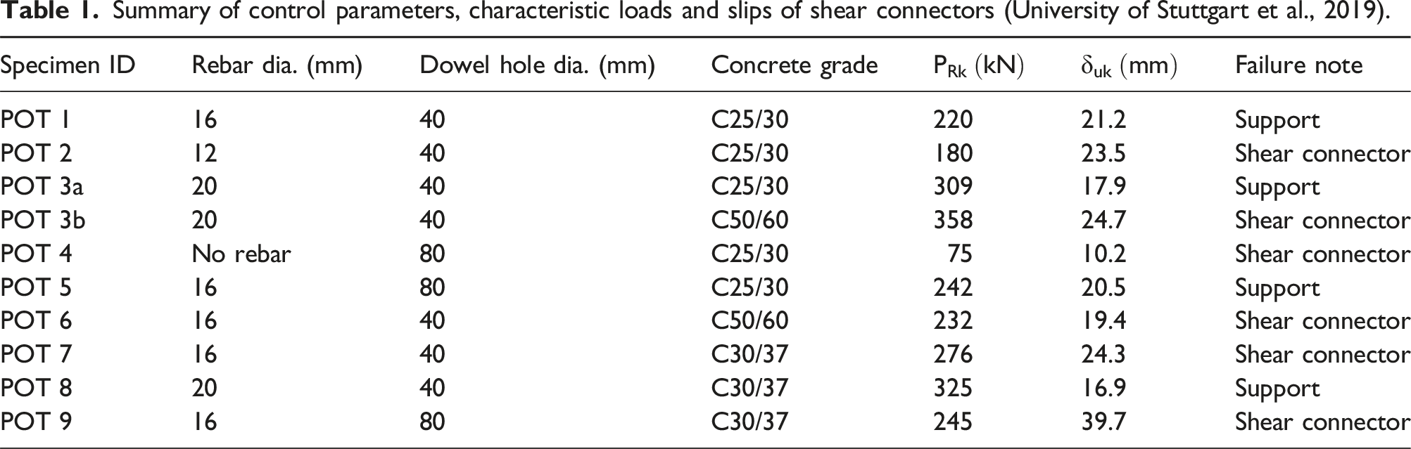
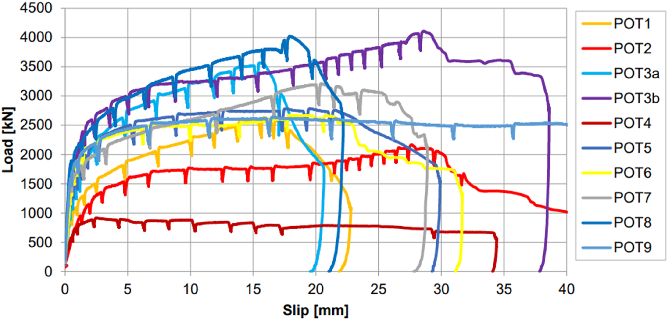
From Table 1 and Figure 2, the effect of concrete strength to the shear resistance can be seen by comparing POT3a (C25/30), POT3b (C50/60) and POT8 (C30/37) as these 3 specimens have same reinforcing rebar diameter of 20 mm and same concrete dowel diameter of 40 mm but concrete strength different. It is found that the higher the concrete strength, the higher the resistance. However, by comparing the resistances of POT1 (C25/30), POT6 (C50/60) and POT7 (C30/37), they have same rebar diameter of 16 mm and dowel diameter of 40 mm, the resistance of POT6 (C50/60) is about 10% lower than resistance of POT7 (C30/37) although its concrete strength is higher. From Figure 2, it can be seen that higher concrete strength (POT6) results in higher stiffness and higher resistance up to the slip about 8 mm. When the slip is greater than 8 mm, the resistance of the specimen POT6 experienced a plateau up to a slip value about 22 mm, however with the slip increasing, the resistance of specimen POT7 experienced an increase up to the slip about 20 mm. The resistance difference is unexpected, although it can’t be excluded that weakness existing in the dowel concrete, the possible reason might be as explained by Aggelopoulos et al. (2021) “This increased ductility and gain in resistance at greater values of slip for the specimen with the lower concrete strength may be explained by the greater deformation of the bar inside the concrete, leading to a different mechanism of load transfer (one that includes bending of the bar with the formation of plastic hinges).” Comparison of POT4 (without rebar), POT1 (rebar 16 mm), POT2 (rebar 12 mm) and POT3a (rebar 20 mm) demonstrates the importance of reinforcing rebar as it significantly affected the shear resistance of the concrete dowel shear connectors. POT4 (without rebar) has no reinforcing rebar in concrete dowel has the lowest shear resistance. POT1 (rebar 16 mm), POT2 (rebar 12 mm) and POT3a (rebar 20 mm) explain that the larger the diameter of the reinforcing rebar, the higher the shear resistance. The effect of diameter of concrete dowel on the performance of concrete dowel shear connector can be seen by comparing the resistances of POT1 (dowel 40 mm) and POT5 (dowel 80 mm), both with concrete grade C25/30, the bigger the dowel diameter, the higher the resistance. However, the resistance of POT9 (dowel 80 mm, concrete C30/37) is lower than that of POT7 (dowel 40 mm, concrete C30/37) although its dowel diameter is bigger. This is possibly due to the larger dowel diameter make the distance between the rebar and the steel web hole edge is bigger than smaller dowel adopted, therefore the early-stage shear load is mainly borne by the dowel concrete, when the reinforcing rebar starts to bear the major shear force, the concrete has been damaged. Therefore when the external shear force increases, the damaged dowel concrete can’t effectively transfer the shear fore to the reinforcing rebar. This force redistribution mechanism reduces the composite function of the concrete dowel with rebar, and the rebar involvement and resistance contribution are impaired due to concrete failure and thus the overall load bearing capacity decreases. From Table 1 and Figure 2, concrete dowel shear connectors show very good deformation capacity, all slips obtained exceed the minimum slip requirement of 6 mm specified in Eurocode 4, which explains this shear connector is ductile. Based on the experimental results, it can be inferred that the diameter of reinforcing rebar dominates the maximum shear resistance, diameter of concrete dowel and concrete strength influence the performance of shear connectors. The effect of the concrete strength related to the rebar diameter used. Small rebar diameter resulted in a decreasing load with increasing concrete strength. A large diameter resulted in an increasing load with an increasing concrete strength.
Description of FE model
No doubt the full-scale specimen test provides reliable information for performance of shear connection adopted in composite slim-floor beam, however, it is expensive and time consuming, therefore, numerical modelling can be considered as an alternative method. In the research presented in this paper, the nonlinear finite element software ABAQUS (2022) is adopted to develop the finite element model and simulate the push out test of concrete dowel shear connector in composite slim-floor beams. The finite element model of push-out test is based on experimental investigation carried out by the University of Stuttgart et al. (2019) as shown in Figure 1. Considering the symmetrical features of the tested specimens, only a quarter of the whole specimen structure is modelled to improve computational efficiency. The main components of the FE model include concrete slab, steel mesh, steel beam section, and concrete dowel with or without reinforcing rebar, as shown in Figure 3. All specimen components are created separately and then assembled. This demonstrative FE model is based on the push out test specimen POT 7, in which the steel beam section is HEB 200, concrete grade C30/37, concrete dowel diameter is 40 mm (hole diameter on steel section web), reinforcing rebar (passing through the centre of the web hole and in the concrete dowel) diameter is 16 mm, the centre-to-centre spacing of concrete dowel is 125 mm. The A252 (mesh grid 200 mm × 200 mm and rebar diameter 8 mm) steel mesh is placed above the steel beam and below the top of concrete slab. FE Model of the push out test and components (shown in a quarter of the specimen POT 7).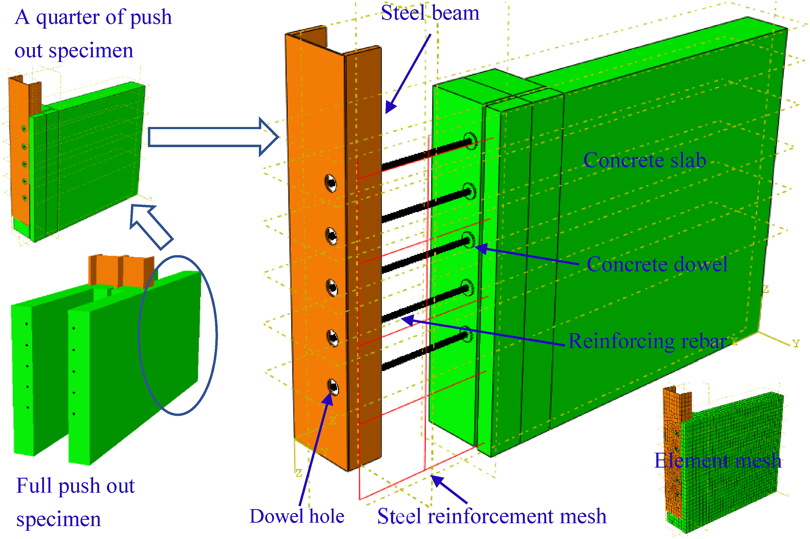
Material properties
The following material properties are adopted in the FE model according to tested specimens. Steel beam section HEB200 of grade S355: yield stress 355 N/mm2, Young’s modulus 210 GPa, Poisson’s ratio 0.3 and density 7800 kg/m3. For the reinforcing rebar in the dowel and reinforcement steel mesh A252 in slab, the yield strength is assumed to be 500 N/mm2, Young’s modulus 210 GPa, Poisson’s ratio 0.3 and density 7800 kg/m3. Concrete damage plasticity model available in the Abaqus software is adopted, in which the cylinder compressive strength 30 N/mm2, tensile strength is assumed to be 10% of the compressive strength, Young’s modulus 25.6 GPa, Poisson’s ratio 0.2 and density 2400 kg/m3, are used. Figure 4 shows the C30/37 concrete compressive and tensile strength and damage mechanism. Other related parameters used in the concrete damage plastic model are: dilation angle Concrete (C30/37) compressive/tensile strength and damage mechanisms.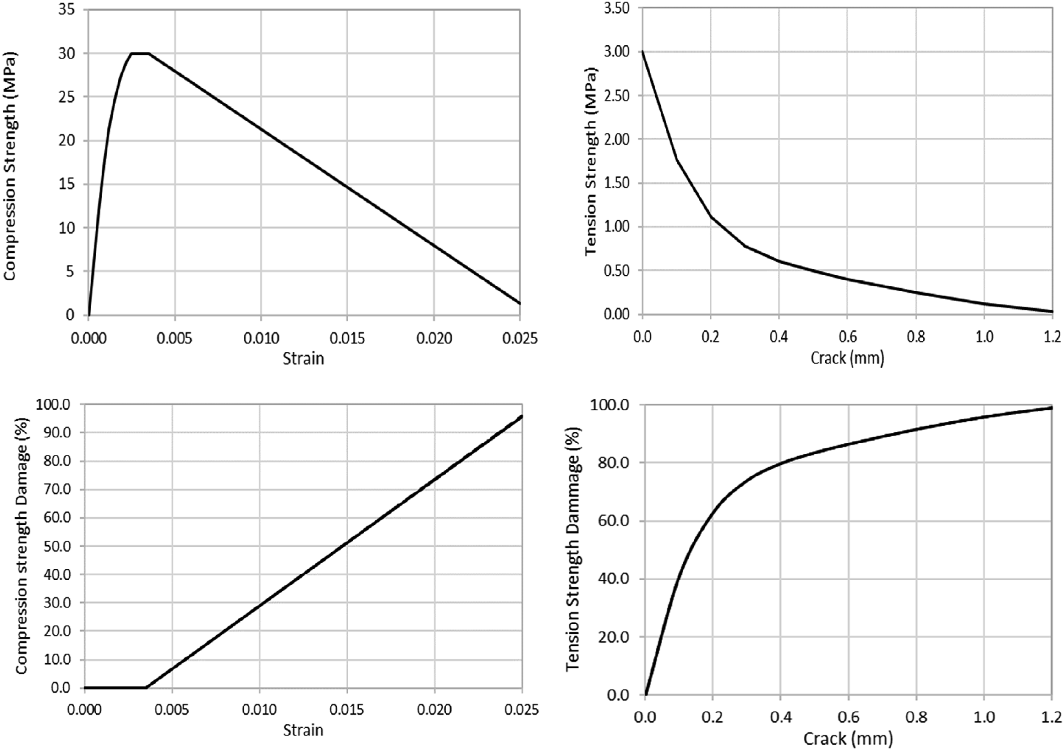
Element type and mesh
The three dimensional eight-node solid brick element (C3D8R) is used in the FE model for the concrete slab, steel beam section, concrete dowel and reinforcing rebar. This eight-node solid brick element has reduced integration with hourglass control and can avoid the shear locking during the simulation under complex stress conditions and is well-suited for the simulation of structure with non-linear material and contacts. To increase the simulation accuracy, finer size of hexahedral element type is allowed around the shear connector position as larger local deformation and stress concentration occurred in this area. After an element size sensitivity analysis, the dimensions of elements for concrete slab and steel beam are mostly 30–40 mm in the axial and transverse directions. The finer element size adopted around the dowel zone is 5–15 mm. The selected element type and size effectively ensured the modelling convergence and accuracy. Two-node truss element (T3D2) type is used to simulate the reinforcement steel mesh in slab. A typical element mesh is shown in Figure 3.
Loading and boundary conditions
The load (by displacement control) is applied from the top of the steel section to push the beam down. It is like the experimental hydraulic actuator loading in the push out test. The movement of the bottom surface of the concrete slab is restrained. Due to the FE model only considering a quarter of the push out tested specimen, two symmetrical planes are assigned in their normal directions to consider the symmetric conditions as shown in Figure 5. Loading and boundary conditions of the FE model.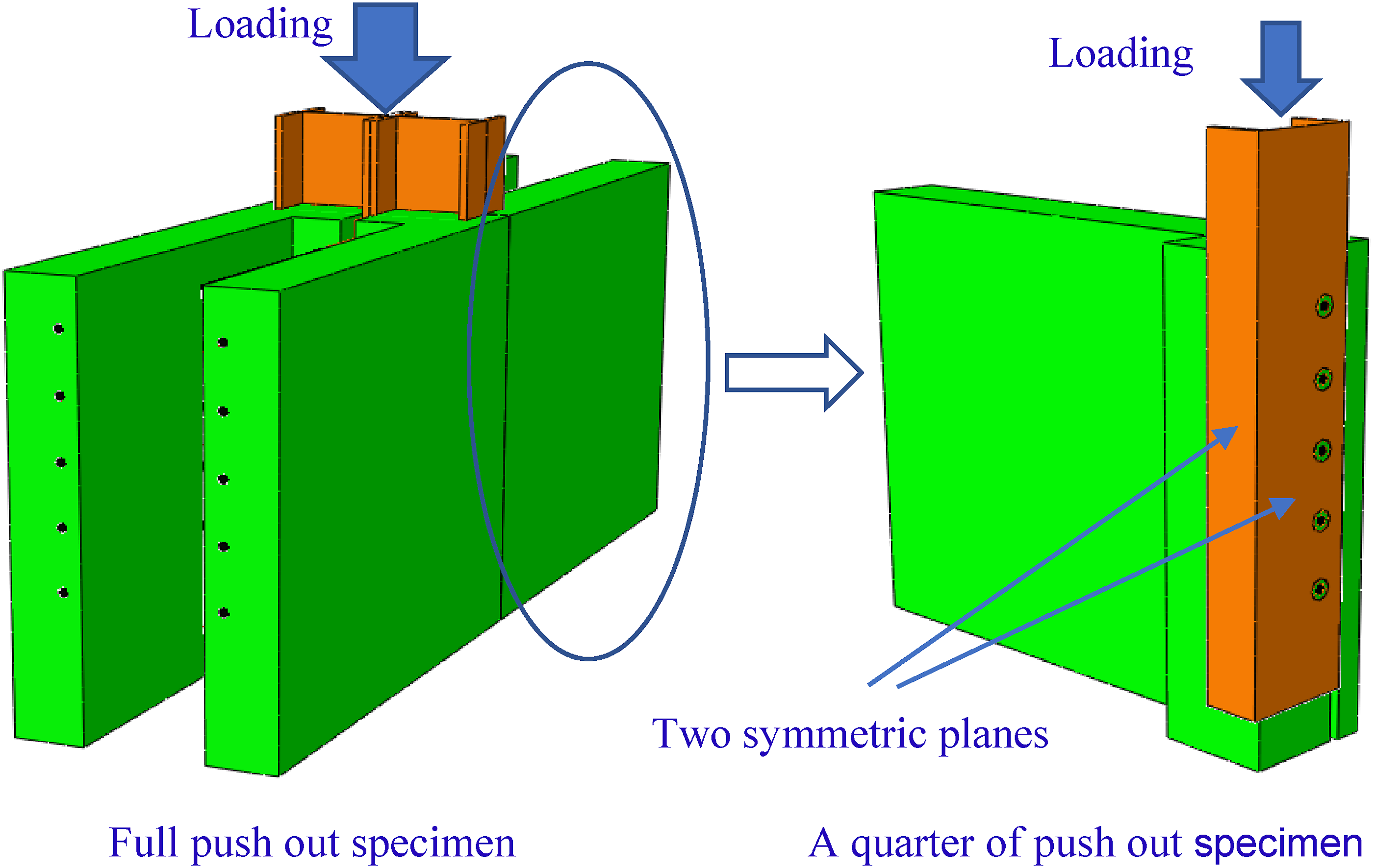
Interaction and constraint
In the composite slim-floor beam system, the main shear resistance is achieved by the dowel shear connector, however the interaction between the concrete and steel members should not be ignored, as the interaction between these members might influence the performance of the composite structure and thus the results of simulation. The interaction behavior between the reinforcing rebar and concrete contact surface is considered as hard contact in normal direction and which only allows a little penetration from master surface to slave surface to ensure the convergence of simulation. In the tangential direction of the contact surfaces, the penalty friction behavior was adopted. Different friction coefficients from 0.1 to 0.5 were selected in the sensitivity study and 0.15 was found to give the best modelling results by comparing with test results, therefore 0.15 is adopted in the FE models. This is supported by Guezouli and Lachal (2012), who conducted investigation on numerical analysis of frictional contact effects in push out tests by sensitivity analysis using frictional coefficient values from 0 to 0.5 and found 0.1 to 0.3 giving best simulation results. The same interaction properties are adopted between steel beam and concrete slab contact surfaces including the concrete dowel and the web hole of the steel beam. To simplify the modelling, the reinforcement steel mesh is embedded in the concrete slab and the reinforcing rebar is tied to the concrete at the dowel center.
Validation of FE model
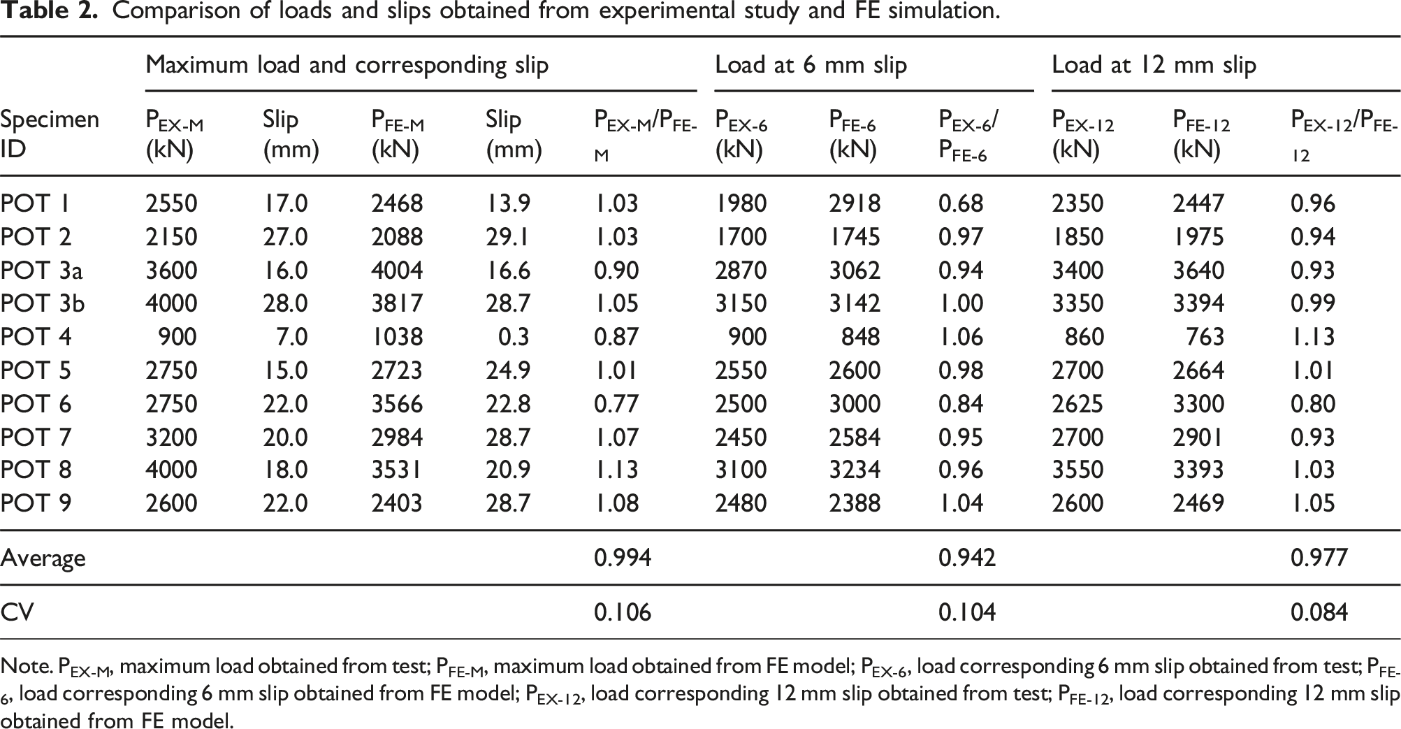
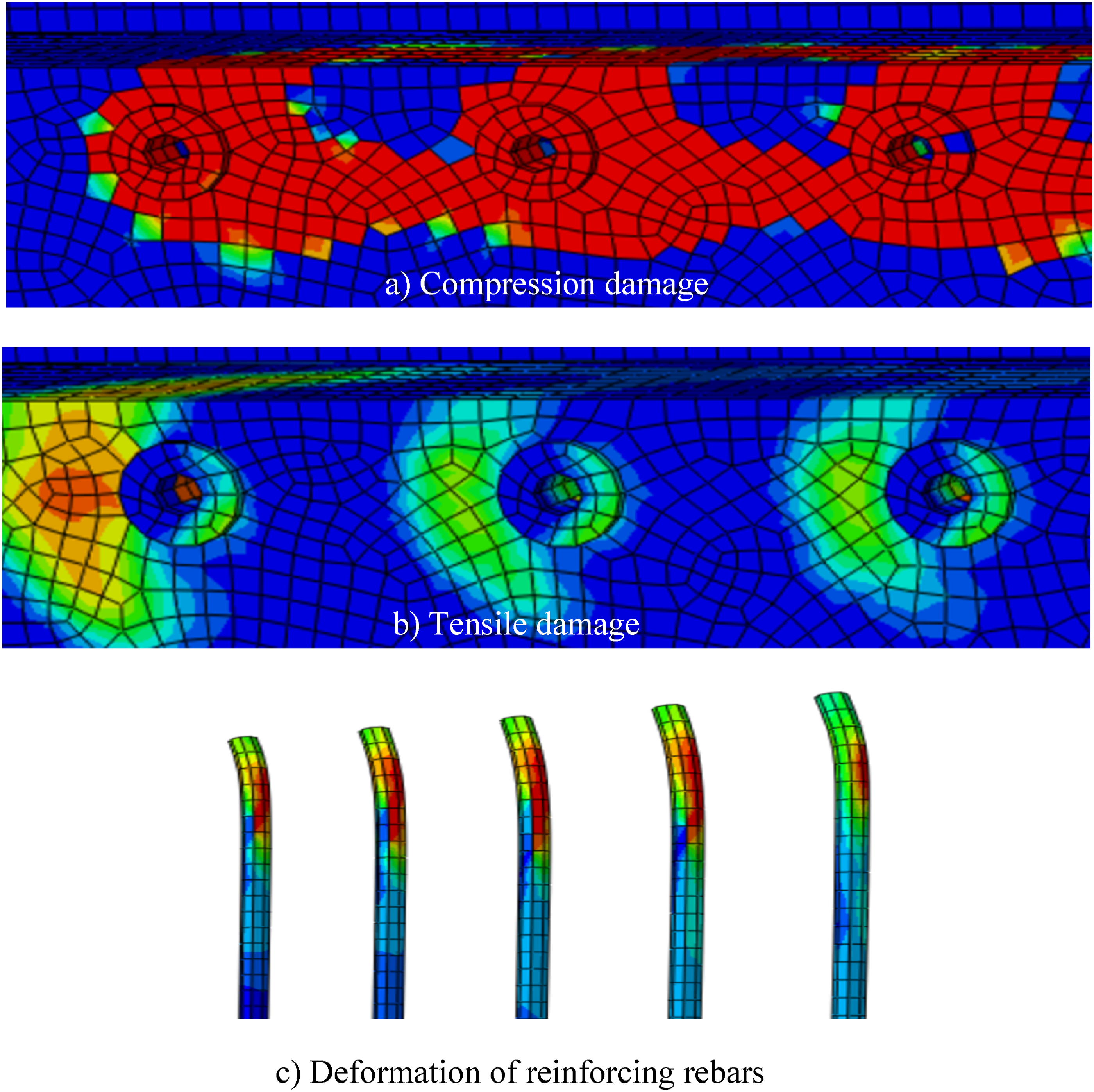
The developed FE model is adopted to simulate the 10 push-out test specimens. Figure 6 shows the comparison of load via slip relationships. It can be seen, good agreement achieved. Although for some specimens, the predicted stiffness is higher than the test results, the load and ductility are well reproduced by the FE modelling. The possible reasons causing the difference between modelling and experimental observation might be the perfect concrete properties and perfect boundary conditions adopted in the FE models but not for the realistic specimens and tests. Table 2 summarizes the maximum load and corresponding slip and loads corresponding to 6 mm and 12 mm slips observed from experimental study and obtained from FE modelling prediction, the difference is within an acceptable range, most less than 10%. In POT 4, although the initial stiffness and maximum load obtained from modelling are higher than those observed in the specimen test, both load-slip curves have similar trends. In POT 6, a big difference is observed between the test result and simulation result, but from the push-out test results shown in Table 1 and Figure 2, the maximum load of POT 6 using C50/60 concrete is lower than that of POT 7 using C30/37 concrete although the initial stiffness of POT 6 is higher than that of POT 7, as explained in the previous section, this is possibly due to the slip increasing leading to a different deformation of rebar inside and thus changed the mechanism of load transfer. Unfortunately, the modelling did not reflect this phenomenon observed from experimental study. However, in the FE modeling, the maximum load of POT 6 is higher than that of POT 7. This reflects the effect of concrete strength to the dowel shear connector. Figure 7 shows the failure modes of dowel and vicinity concrete. It can be seen that relative slip between steel section and concrete applying a shear force to the dowel, which crushes the concrete of dowel and dowel vicinity indicated by concrete compressive damage. The steel web also gives splitting action to dowel concrete, this is indicated by tensile damage. The dowel concrete transfer the shear force to the reinforcing rebar inside the dowel and this force bends the rebar. In general, the validation shows the developed FE model successfully captured the main structural behaviors of the shear connection, such as maximum loads and load versus slip relationships although disparity exists. The validation supports the developed model to be adopted for parametric study. Comparison of load via slip curves obtained from FE models and tests. Comparison of loads and slips obtained from experimental study and FE simulation. Note. PEX-M, maximum load obtained from test; PFE-M, maximum load obtained from FE model; PEX-6, load corresponding 6 mm slip obtained from test; PFE-6, load corresponding 6 mm slip obtained from FE model; PEX-12, load corresponding 12 mm slip obtained from test; PFE-12, load corresponding 12 mm slip obtained from FE model. Concrete damage around the connection: (a) compression damage, (b) tensile damage and (c) deformation of reinforcing rebars.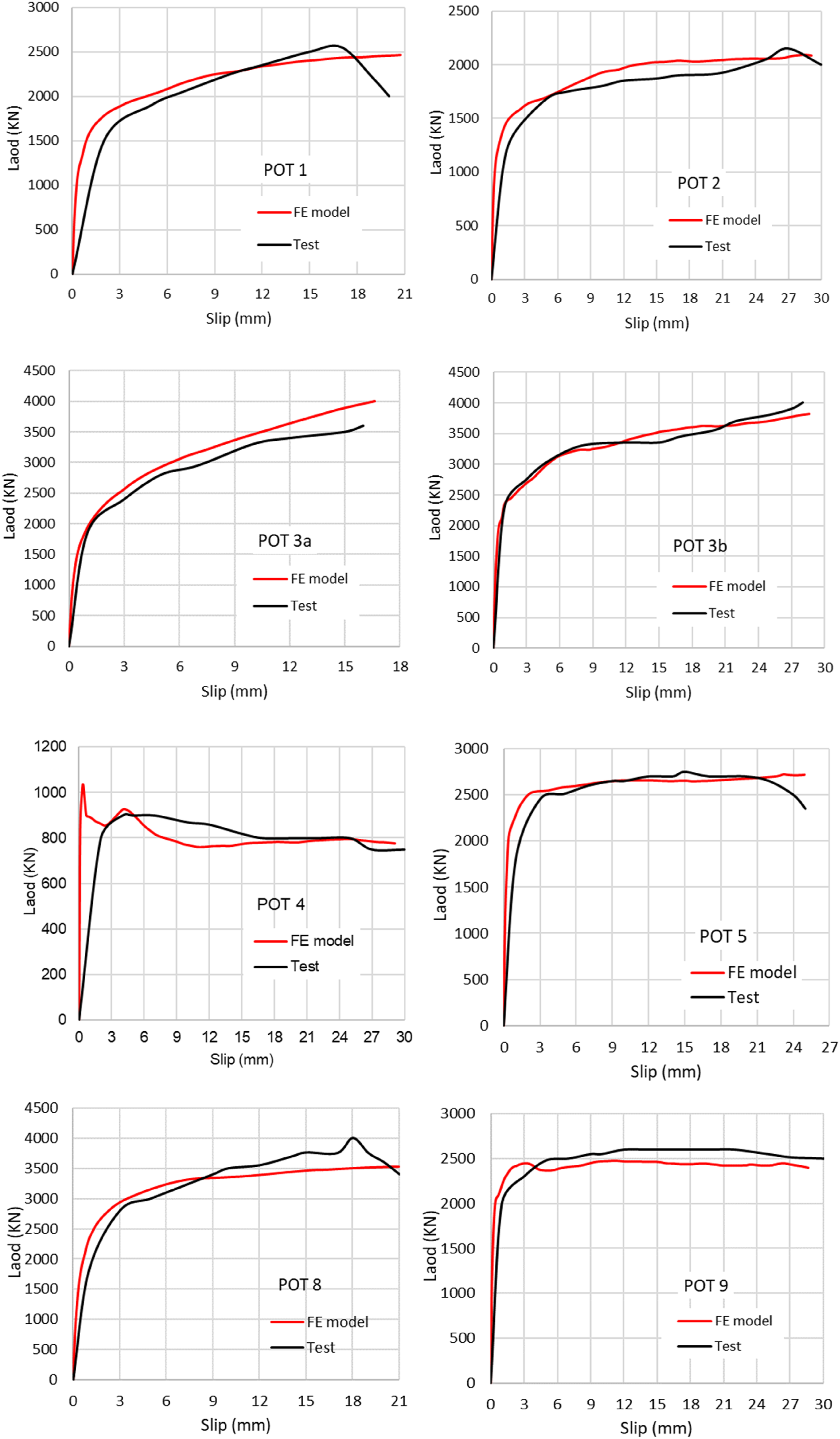
Parametric study
Although the push out tests and FE model validation covered a reasonable scope of shear connector parameters, to further understand the behavior of this type of shear connections adopted for composite slim-floor beams, a parameter study, covering different concrete dowel sizes, different concrete strengths and different reinforcing rebar diameters, are conducted and presented in the following sections.
Effect of concrete dowel sizes
In this parameter study, two series of scenarios are taken into consideration. In the first series, five different concrete dowel diameters 40 mm, 60 mm, 80 mm and 100 mm are considered. Other key features of the shear connections are concrete strength C30/37 and reinforcing rebar diameter 16 mm. The second series of shear connections are the same as the first series, but no reinforcing rebar employed in the concrete dowel. Figure 8 compares the load-slip relationships of these two series of shear connections adopting different dowel diameters, it can be seen that for shear connectors with 16 mm rebar used, generally the shear connection stiffness and load bearing capacity increase with the concrete dowel diameter increasing, although increasing the dowel diameter from 40 mm to 60 mm the load capacity increased very little, however, when the dowel diameter increased from 80 mm to 100 mm, the maximum load capacity decreases. This is possibly due to the larger dowel made the distance between the rebar and the web hole edge is bigger than smaller dowels adopted, therefore the early-stage shear force is mainly borne by the concrete, when the reinforcing rebar started to bear the major shear force, the concrete was damaged, this force redistribution mechanism reduced the composite function of the concrete dowel with rebar, so the rebar involvement and resistance contribution were impaired and the overall load bearing capacity decreases. For shear connections without reinforcing rebar, the shear connection stiffness and load bearing capacity increase with the concrete dowel diameter increasing. In addition, the comparison between shear connections without reinforcing rebar and with reinforcing rebar adopted clearly shows the shear load increased with the rebar adopted. Load-slip relationships of shear connections with different concrete dowel diameters (concrete strength C30/37).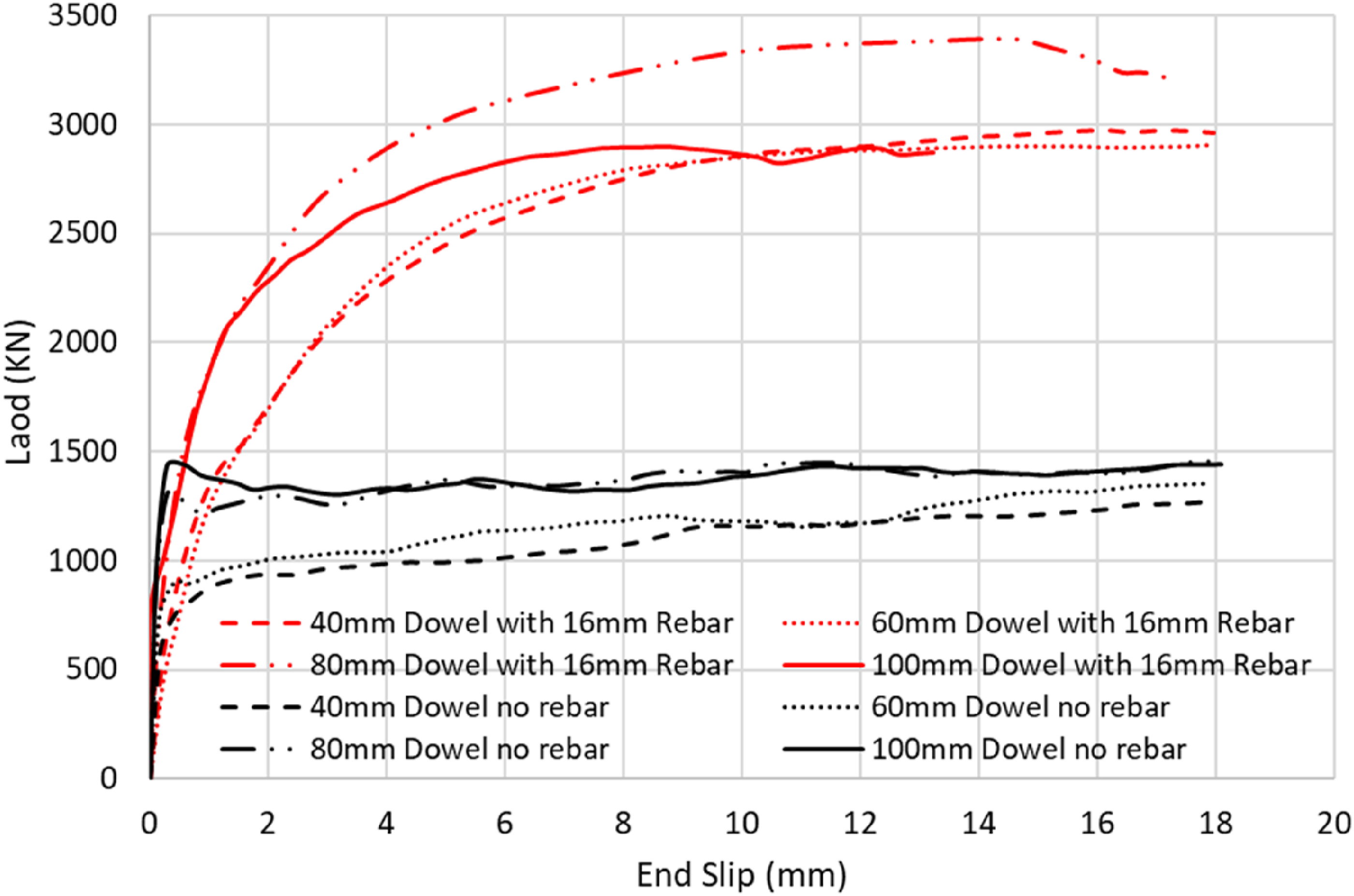
Effect of the concrete strengths
Four concrete grades are considered in this parameter study to consider the effect of concrete strength on the behavior of shear connections with or without reinforcing rebar. All shear connections have concrete dowel diameters of 40 mm, but one series uses 16 mm rebar in the dowel center, while the other series has no rebar. Figure 9 shows the load-slip relationships. As expected, with the concrete strength increasing, both stiffness and load capacity increase regardless of whether rebar employed or not. The comparison clearly shows that concrete strength affects the shear resistance significantly. As well, the comparison demonstrated the great function of reinforcing rebar to shear resistance, or the reinforcing rebar dominates the shear connector strength. Load-slip relationships of shear connections with different concrete strengths (dowel diameter 40 mm).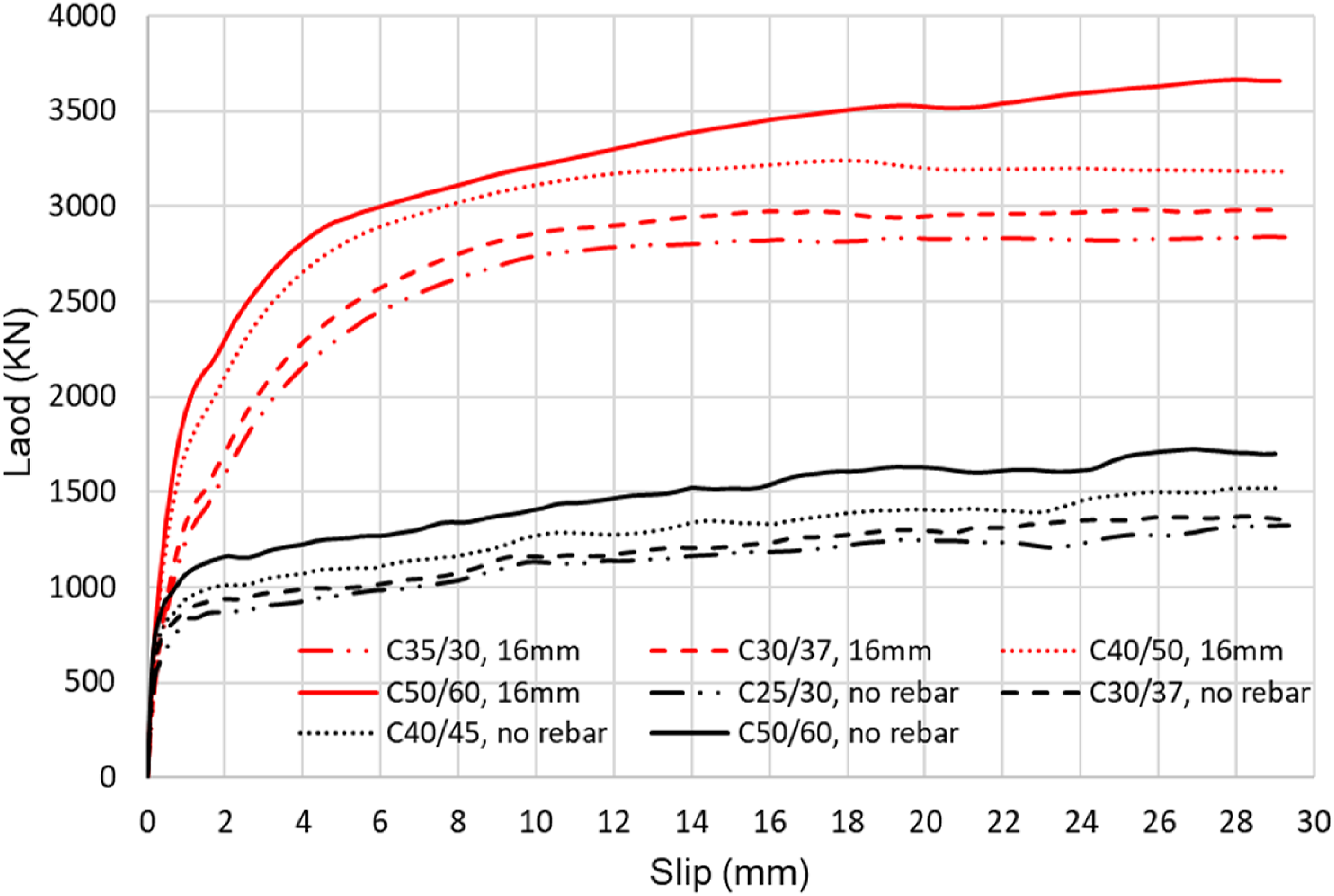
Effect of diameter of reinforcing rebar in dowel
To explore the effect of reinforcing rebar in the concrete dowel to the behavior of shear connection, in this parameter study, concrete strength C30/37 and dowel diameters 40 mm are adopted for all shear connections. Five diameters of rebar, or no rebar (0 mm), 12 mm, 16 mm, 20 mm, 24 mm are adopted in the simulations. Figure 10 shows the load-slip relationships. It can be seen, load bearing capacity of shear connection significantly increased with the increasing of the rebar diameter. Load-slip relationships of shear connections with different rebar diameters (dowel diameter 40 mm, concrete strength C30/37).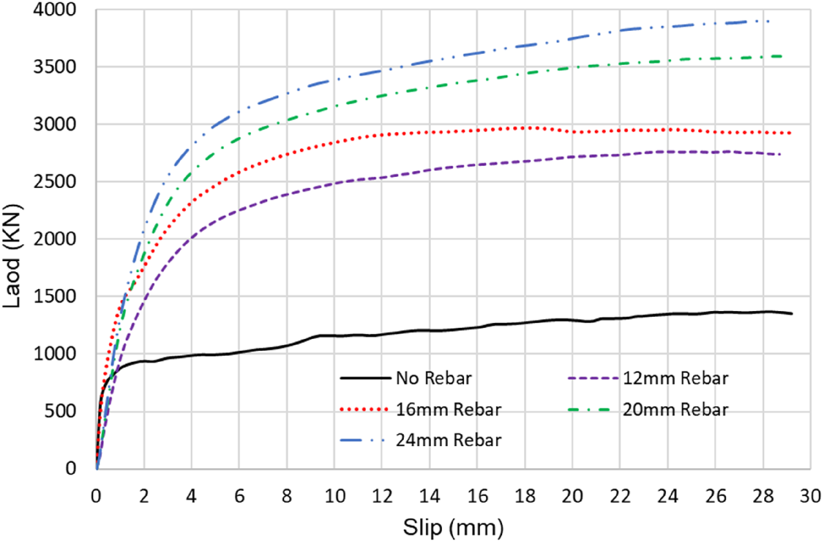
Simple prediction method of shear resistance
The force transfer mechanisms, resistance, and failure of concrete dowel with rebar have been discussed in previous sections. For the resistance of the shear connector (
Concrete dowel resistance
Although the concrete dowel mainly affords compressive resistance during the push out tests, the tensile strength of concrete dowel is also included for high accuracy, therefore both concrete compressive resistance (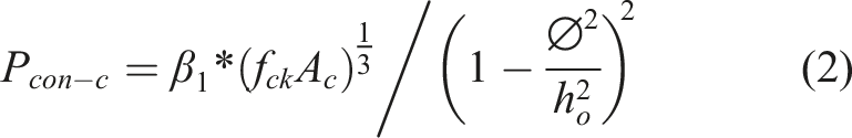

Based on the research presented in this paper, the factor 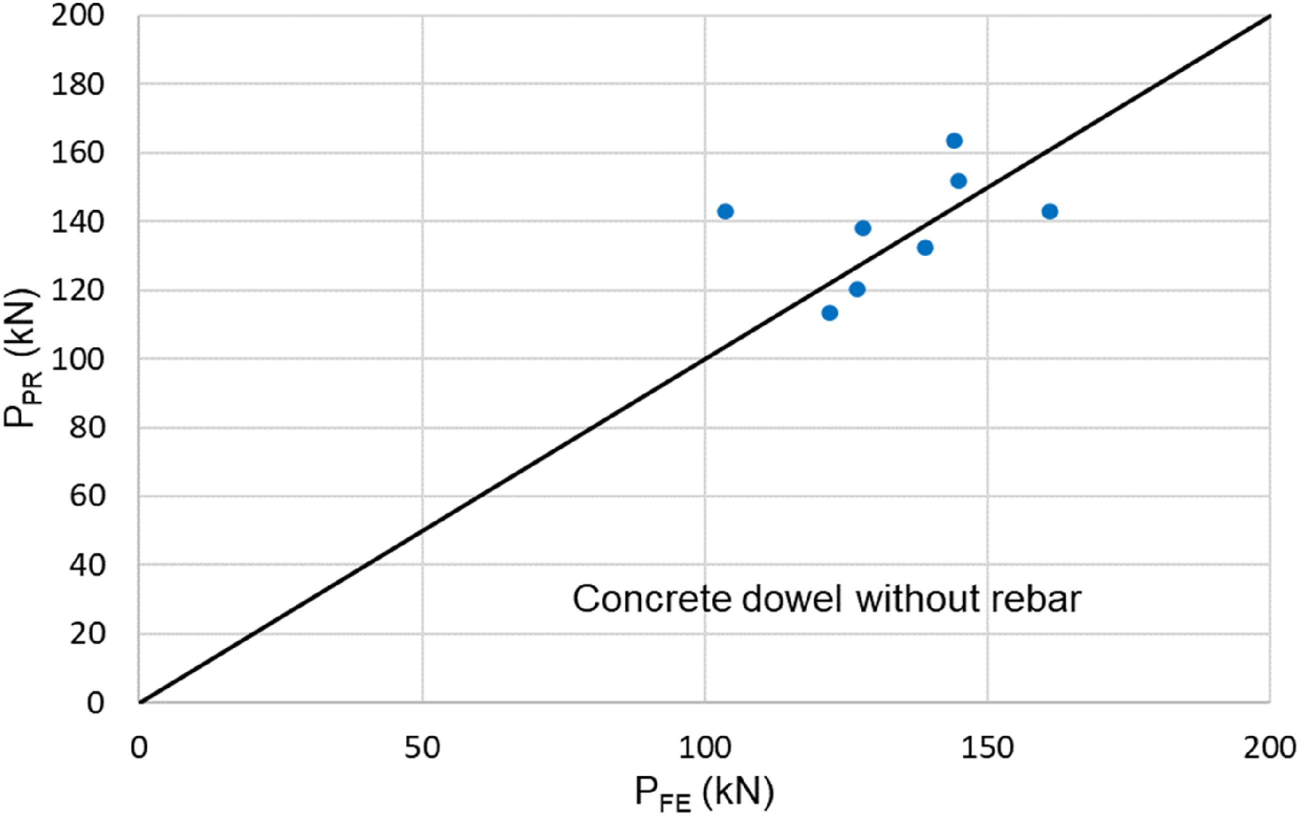
Reinforcing rebar resistance
For reinforcing rebar passing the concrete dowel, two scenarios are considered based on the possible failure modes of the shear connector. The first one is that the dowel concrete failed before the reinforcing rebar yielded. The shear resistance contributed by the reinforcing rebar can be calculated from the equivalent strain of the concrete dowel and the modulus of elasticity. The second one is both dowel concrete and reinforcing rebar reached the ultimate state, the yield strength of the rebar will dominate the shear resistance of the rebar. Therefore, eqs. (4) and (5) are adopted to consider the shear resistance of reinforcing rebar under the first and second scenarios respectively. It must be noted, the shear action of the reinforcing rebar occurs in two planes during the push out test.

For eq. (4), the concrete of the shear connector and the reinforcing rebar passing through the dowel are considered integration, the rebar deformation is relatively small and similar to the dowel concrete, therefore the strain of reinforcing rebar may be the same as the strain of the concrete dowel. However, for eq. (5), the shear resistance of the reinforcing rebar (
Additional frictional and adhesion action
Due to the complex interaction between composite structural members, it is still difficult to quantify the influence onto the shear resistance exactly. The current calculation theory is insufficient to provide accurate and detailed numeration, but this additional friction action is indeed existing and plays an enhancement to the resistance capacity of the composite slim floor beams. Therefore, an influence coefficient (
Shear resistance of concrete dowel shear connector
As discussed in previous sections, two failure modes are considered for shear connector, or dowel concrete failed before rebar yielded and both concrete and reinforcing rebar failed, therefore, the resistance of the shear connector may be calculated by the strength in each element of the shear connector, that is, as shown in eq. (1). In which, the compressive strength of the dowel concrete (eq. (2)), the tensile strength of the dowel concrete (eq. (3)), the shear resistance of the reinforcing rebar passing through the concrete dowels (eqs. (4) and (5)), and an additional frictional action influence coefficient (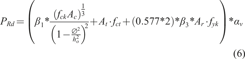
All the variables in the equation are the same as defined in previous equations.
When considering the shear connector with only concrete failure but the reinforcing rebar has not reached its yield strength, due to the rebar strain is similar to the concrete dowel strain, therefore the method is named “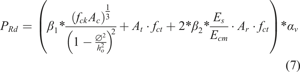
All the variables in the equation are the same as defined in previous equations. According to the regression analysis of the test results, factors
Validation of proposed prediction methods
The proposed method eqs (6) and (7) are used to calculate the shear resistance and compared with the push-out test results and parametric study. Figure 12(a) shows a comparison of the shear resistance ( Comparison of shear resistance predicted by proposed method and push-out test results.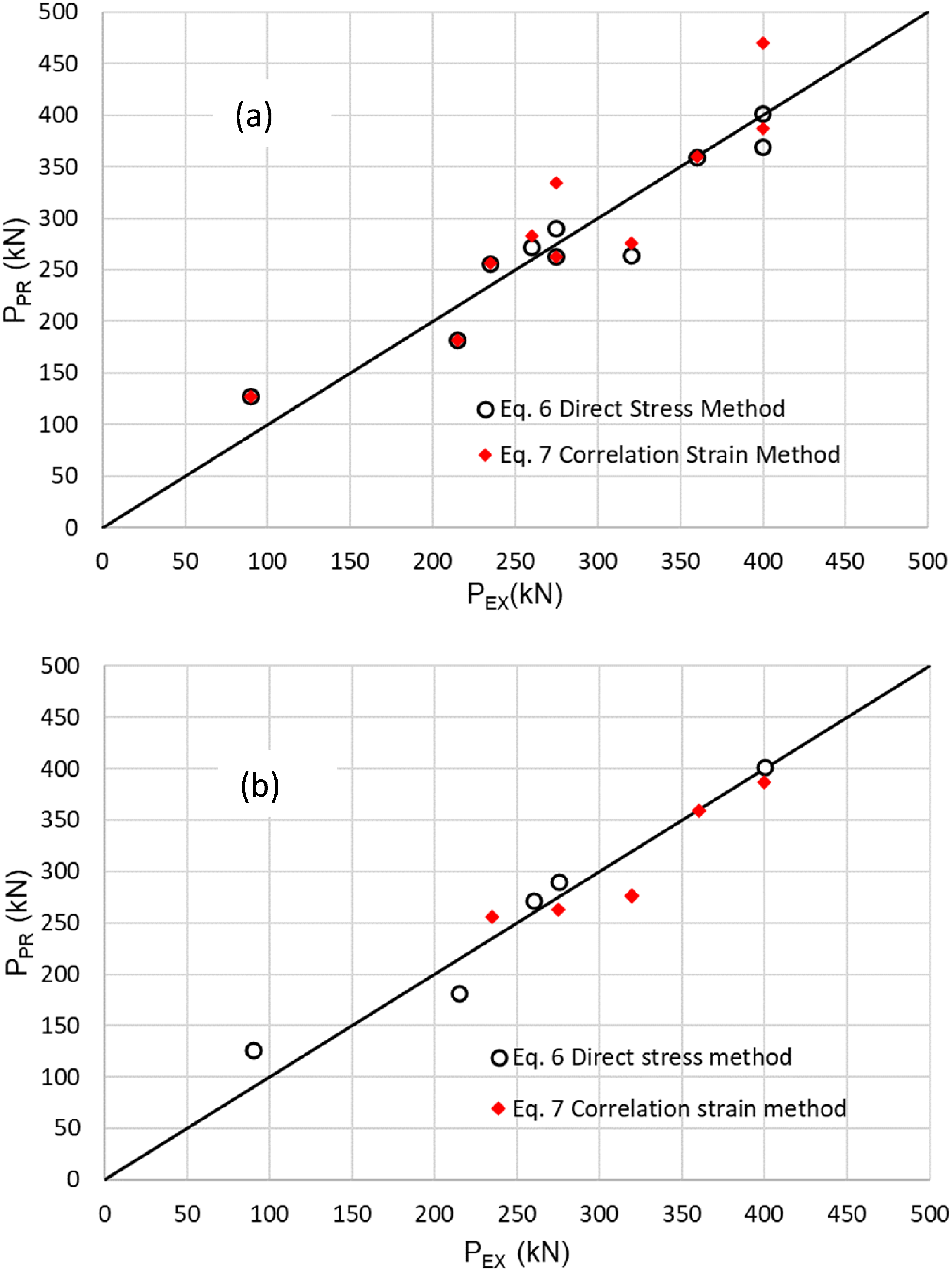
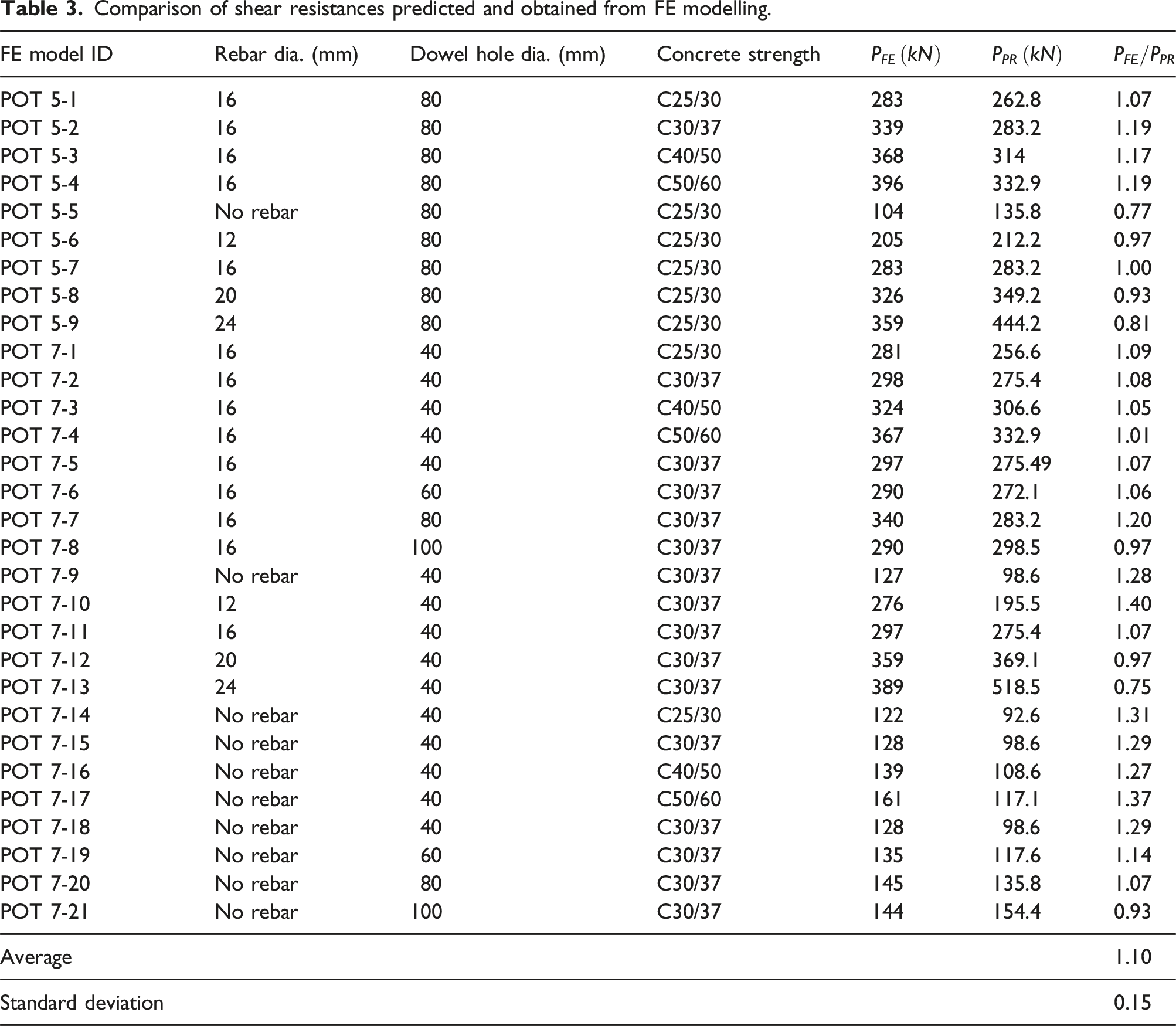
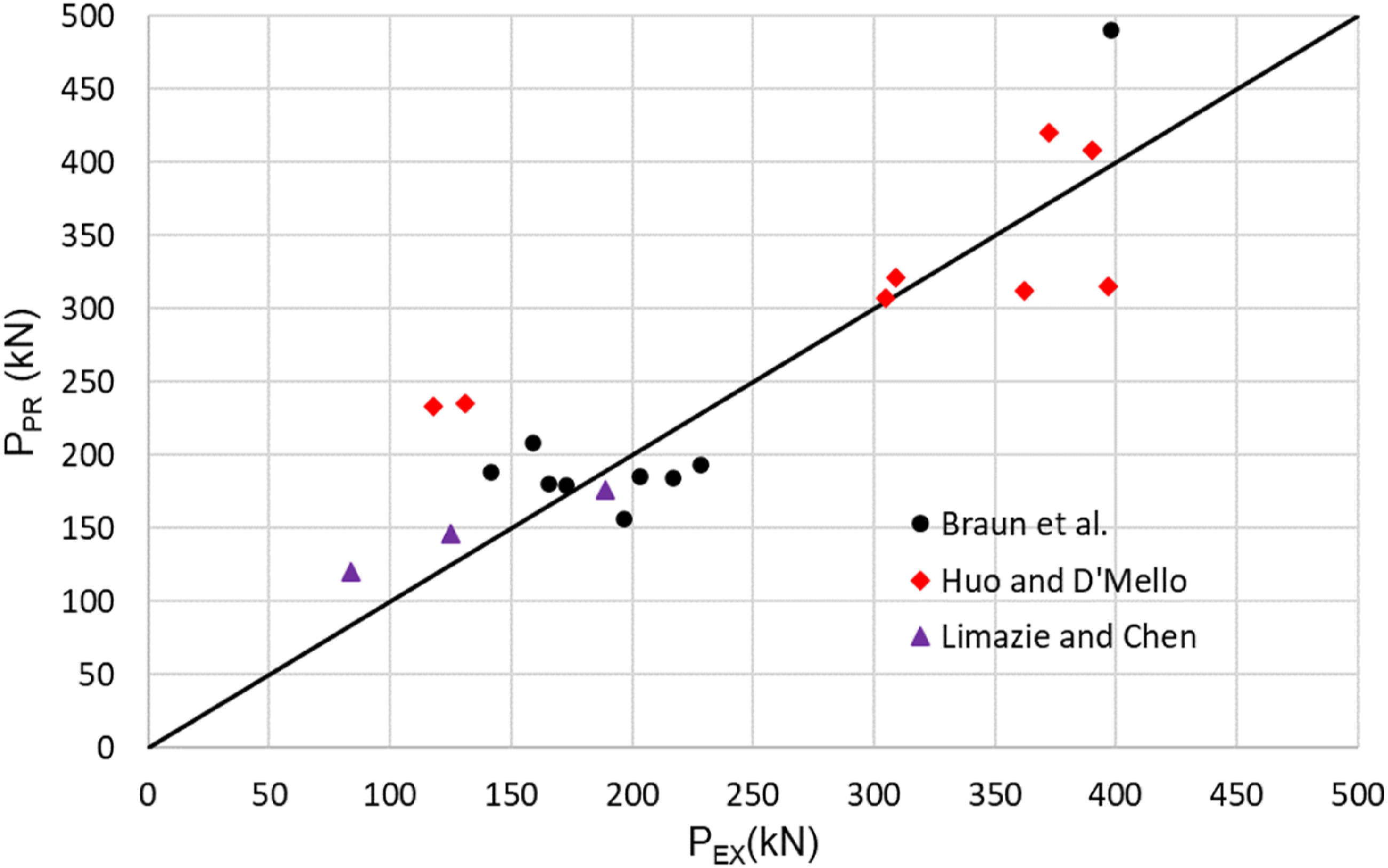
Figure 13 shows the comparison of shear resistances predicted by proposed methods with the maximum loads obtained from FE simulations summarized in Table 3. The average ratio of resistance by FE modelling to resistance by prediction is 1.10 and standard deviation 0.15. Reasonable accuracy achieved although the prediction is slightly conservative, but this is on safer side in design. Figure 14 shows a comparison of resistances of dowel connectors predicted by proposed methods and test results from references (Braun et al., 2015; Huo and D’Mello, 2013; Limazie and Chen, 2017), as well reasonable agreement can be seen although some results scatter. The average ratio of resistance by experiments to resistance by prediction is 0.94 and standard deviation 0.217. Comparison of shear resistances predicted by proposed methods and obtained from modelling results. Comparison of shear resistances predicted and obtained from FE modelling. Comparison of shear resistance predicted by proposed methods and test results from references.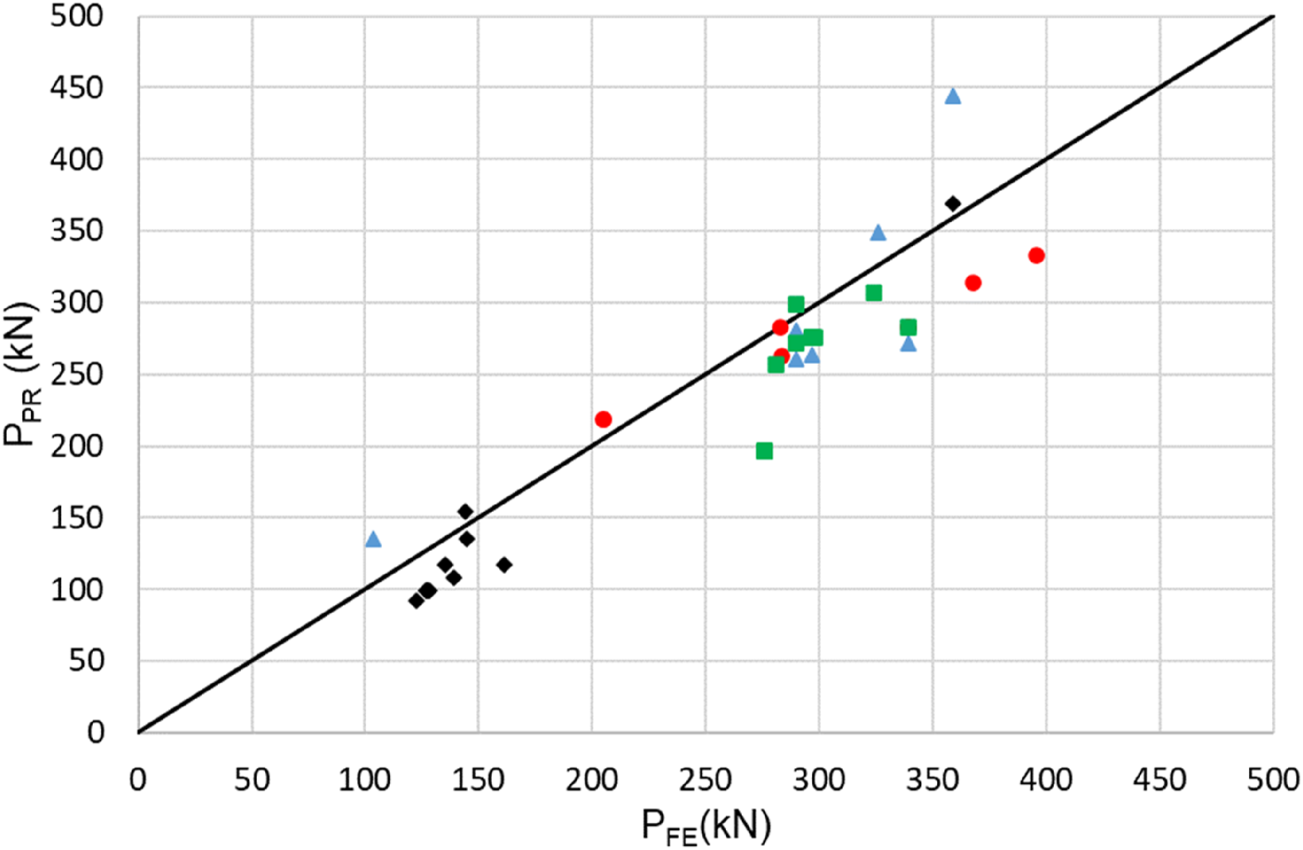
Conclusions
This paper presents the development of finite element model of push-out test specimen and validation against experimental results with acceptable accuracy. The parameter study covering different concrete grades, dowel diameters and reinforcing rebar diameters, highlighted the effect of concrete strength, dowel size and rebar diameter to the resistance of concrete dowel shear connectors. The simple method proposed for prediction of the shear resistance of dowel shear connectors, validated against modelling and available experimental results showing acceptable accuracy, can be reference for design. By the research presented in this paper, the following conclusions may be drawn: • The finite element model developed using the ABAQUS software can be used to simulate similar dowel shear connections and predict shear resistance and slip behavior. Comparing the maximum load and corresponding slip and loads corresponding to 6 mm and 12 mm slips observed from experimental study with those obtained from FE modelling prediction, their differences are within an acceptable range, most less than 10%. However, the current FE model doesn’t capture the load transfer mechanism change resulted from the slip increasing or rebar deformation. • The adoption of reinforcing rebar promotes shear resistance significantly. According to the parameter study, for 40 mm dowels, using 12 mm rebar increases the dowel shear resistance 117% with dowel without rebar. For 80 mm dowels, using 12 mm rebar increases the shear resistance 97%. The size of reinforcing rebar has distinct effect to the load capacity of shear connection. The bigger the rebar diameter, the higher the shear resistance of dowel shear connector. Based on the parameter study, for 40 mm dowel, increasing rebar diameter 4 mm, the dowel shear resistance increases 8%∼20%. For 80 mm dowel, the dowel shear resistance increases 10%∼30% with rebar diameter increasing 4 mm, however it appears the bigger the rebar diameter, the lower the increase of shear resistance. • The concrete strength has significant influence on the load capacity of shear connection. The higher the concrete strength, the higher the shear resistance of shear connector. According to the parameter study, for 40 mm dowel without reinforcing rebar, with concrete strength increasing 10 N/mm2, the dowel shear resistance increases 8%–16%. For 40 mm dowel with a reinforcing rebar of 16 mm diameter, when the concrete strength increases 10 N/mm2, the dowel shear resistance increases 8%–13%. For 80 mm dowel with 16 mm reinforcing rebar, when the concrete strength increases 10 N/mm2, the dowel shear resistance increases about 7%–9%. • With the concrete dowel diameter increasing, generally the shear resistance increases. For dowel without reinforcing rebar, comparing with the shear resistance of dowel with 40 mm diameter, the resistances of dowels with diameter 60 mm and 80 mm increase 5% and 13% respectively, however the resistance of dowel with 100 mm diameter is nearly the same as the resistance of dowel with 80 mm diameter. For dowel with a 16 mm reinforcing rebar adopted, comparing with the shear resistance of dowel with 40 mm diameter, the resistance of dowel with 60 mm diameter is similar but the resistance of dowel of 80 mm diameter increases 14%. The shear resistance of dowel with 100 mm diameter decreases 15% compared with shear resistance of dowel with 80 mm diameter. • The proposed simple calculation method can be used to predict the shear resistance of concrete dowel shear connectors with/without reinforcing rebar. To ensure the prediction accuracy, it is important to judge the rate of rebar resistance to pure concrete dowel resistance before selecting the appropriate calculation formula. For the predicted shear resistance of concrete dowel shear connection, the difference is within an acceptable range, most less than 10%. The average ratio of resistances by modelling to prediction by simple calculation method is 1.1 with standard deviation 0.15. • It must be pointed out, although the parameters chosen in the parameter study cover key parameters that may affect the resistance of dowel shear connection, and which complements and extend the experimental study, the chosen parameters are limited for the specific slim-floor composite beam pattern. In fact, the steel beam section/dimension, the reinforcing rebar position in the dowel and the concrete slab/beam dimension etc. may affect the dowel design and resistance, therefore further research is necessary for slim-floor composite beam system.
Footnotes
Declaration of conflicting interests
The author(s) declared no potential conflicts of interest with respect to the research, authorship, and/or publication of this article.
Funding
The author(s) disclosed receipt of the following financial support for the research, authorship, and/or publication of this article: The research leading to these results is part of a joint project of the University of Bradford, the University of Stuttgart, the University of Trento, the Steel Construction Institute, ArcelorMittal and Lindab S.A. The authors gratefully acknowledge the funding received from the European Community Research Fund for Coal and Steel under grant agreement number RFSR-CT-2015-00020.