
Abstract
When Perfobond Rib shear connectors are used as flexural materials in structures such as bridges, they show flexural shear behavior due to external force, rather than direct shear behavior. The aim of this study is thus to analyze the difference between both behaviors. First, we prepared a specimen to analyze direct shear behavior using Perfobond Rib shear connectors, analyzed the characteristics of behavior with a push-out test and proposed a formula of shear resistance assessment. Proposed formula shows a relatively good fit with less than 10% error. A flexural shear test was then conducted based on the result of the direct shear test. Based on the static flexural test it analyzed the flexural behavior and the flexural shear stress it calculated. Direct shear stress and EN 1994-1-1 to lead and be calculated, it compared the flexural shear stress and it analyzed in about the shear resistance stress which it follows in load direction. Finally, we compared both test results, and the comparison showed that the flexural shear stress is approximately 6% stronger than the direct shear stress.
Keywords
Introduction
The most important factor to be considered in designing and constructing a composite structure is the combined movement behavior of steel and concrete. Since the deformation characteristics of steel and concrete differ, shear force is generated between the two materials by external force and environmental changes. Shear force is likely to cause relative displacement between the two materials, followed by degradation of stiffness and strength of the structure. Therefore, a shear connector is needed to control the relative displacement and resist the shear force generated in the boundary interface between steel and concrete.
A variety of new shear connectors is currently being developed to overcome the drawbacks of head stud shear connectors. The most active study is that of Perfobond Rib shear connectors. Perfobond Rib shear connectors show excellent shear resistance performance and cause very little relative deformation between steel and concrete before a yield point due to their high stiffness.
For the safe and efficient use of Perforbond Rib shear connectors, it is essential to investigate mechanical behaviors and evaluate the performance of shear resistance. In existing studies, a variety of specimens have been used and the behavior characteristics and shear resistance performance of Perforbond Rib shear connectors have been investigated through Push-Out Tests2–4. However, when Perforbond Rib shear connectors are used as flexural materials in structures such as bridges, they show flexural shear rather than direct shear behavior, due to external force 5 . A study on flexural behavior is thus needed for this case as the flexural shear behavior significantly differs to that of destruction, compared to direct shear behavior.
Therefore, in this study, a direct shear test and a flexural shear test were performed to more specifically determine the direct and flexural shear behavior of a structure in which Perfobond Rib shear connectors are used. First, we prepared a specimen to analyze the direct shear behavior using Perfobond Rib shear connectors, analyzed the characteristics of behavior using a push-out test and proposed a formula for shear resistance assessment. In addition, we prepared a specimen to analyze flexural shear behavior based on the result of the analyses and investigated behavior of the specimen by conducting a static flexural test for the structure through four points loading. Based on the result of the direct and flexural shear behavior tests, the difference between direct shear stress and flexural shear stress of the specimen using Perfobond Rib shear connectors was identified.
Basic Theory
Calculation of the Degree of Shear Connection(η) of a Composite Structure
The degree of shear connection in a composite structure, which is the level of composition between two materials in a steel-concrete composite structure, can be calculated from equation (1) as follows.

Under the non-composite condition, which indicates that there is no shear connector, η = 0 and Pshear = 0. Therefore, the strength of a composite structure is Msteel, which is the bending strength of a steel part. In addition, the full composition implies the perfectly harmonized behavior of steel and concrete. In this case, η >1 and Pshear > (Pshear)fsc. However, since in most composite structures, the longitudinal shear transfer device is weaker than the composite beam, they show 0 <η <1. As a result, the flexural force strength, Mpsc, of a composite structure can be explained with the degree of Pshear and the degree of shear connection (η).
EN 1994-1-1 (Eurocode 4. ENV:1994) 6 presents the flexural shear stress of a steel-concrete composite structure using the degree of shear connection (η), as shown in the following equation (2).

Where τ u is the longitudinal shear stress, which applies to the load in the right angle, η is the degree of shear connection, Ncf is the strength of concrete in the compressed side in the case of complete composition, b is the length of cross section and Ls + L0 is the distance from the loading position to the end of the specimen.
As shown in section 3.1, specimens have been prepared with 4 variables to calculate the direct shear strength of Perfobond Rib shear connectors. The amount of relative slip, which varies according to changes of load, is measured using the push out test proposed in EN 1994-1-1. With the results measured, the behavior characteristics of Perfobond Rib shear connectors have been analyzed according to four variables.
Fabrication and Configuration of Direct Shear Behavior of Specimens
With four experimental variables, five specimens were prepared to verify the direct shear strength of a specimen adopting the Perfobond Rib shear connectors. The four experimental variables that determined by reference to previous research include: (i) the existence of holes inside the Perfobond Rib shear connector, (ii) the number of holes inside the Perfobond Rib shear connector, (iii) the existence of reinforced bar in the holes and (iv) the horizontal interval between holes1–3.
Material properties of direct shear behavior test

Material properties of direct shear behavior test
To test the strength of the concrete specimens, a compression strength test was performed with three of the specimens as proposed in the Korea Structural Concrete Code. The strengths of the three specimens were measured as 32.95 MPa, 26.34 MPa and 33.73 MPa and the average strength was 31.01 MPa.
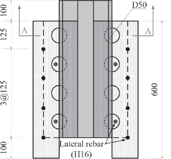
Front view of the specmens

Cross-section A-A in Figure 1
Names of specimens and parameters

To identify the difference between the shapes of the shear connectors and performances depending on experimental variables, all shear experimental specimens are tested using the direct shear test (Push-out Test) in accordance with the proposal of EN 1994-1-1. In addition, in order to find a relative displacement in the vertical direction of concrete and steel according to an increase in weight, LVDT is installed and measured. Furthermore, a 20 mm thick neoprene pad is installed under the specimen to minimize destruction of concrete due to the differential stress that occurs in concrete at both sides. Also, oil is applied between the concrete and steel to minimize the resistance caused by friction between the concrete and steel. Static load is applied in the vertical direction.
Results and Analysis of Direct Shear Behavior Test
The direct shear test on Perfobond Rib shear experimental specimens was performed based on the variables outlined in the previous section.

Breaking of specimen in push-out test
Result of push-out test

According to the analysis of the test results, similar test results were found in all Perfobond Rib shear connectors, except for the PR-1 specimen. All specimens, excluding the PR-1 specimen, show initial cracks on both sides of the concrete between 320 kN and 370 kN. In addition, the specimens were damaged by vertical cracks generated inside the bottom of the concrete because the relative slip amount increases after the maximum load was reached. After the maximum load was reached, the function of the shear connectors had almost dissipated. As a result, relative slip amount significantly increased and the concrete and steel separated. The specimens then became rapidly damaged. However, the PR-5 specimen with lateral reinforced bar inserted shows 5%–19% higher performance on load resistance and has 29.4%–99.8% higher relative slip, compared to other specimens.

Load- slip curve between concrete and steel of all specimens
From the analysis of the test variables, which are the main factors influencing the Perfobond Rib connectors, the structural mechanism of the Perfobond Rib connectors is identified and the formula to assess the direct shear strength of a specimen using Perfobond Rib connectors is proposed.
First, two separate tests for the specimen without holes (PR-1) and those with holes (PR-2, PR-3 and PR-4) were performed to identify the effect of Perfobond Rib shear connectors on the horizontal direction. The number of holes varies depending on the distance between holes. The effect on concrete dowel function was analyzed using the modified variables. The PR-1 specimen resists shear only with the end bearing capacity of the rib because there is no hole inside Perfobond Rib shear connectors. At this time, it is assumed that the end bearing capacity of the PR-1 specimen is 213 kN, which is the maximum resistance of the PR-1 specimen. As shown in
In this study, the number of holes differs from 3 to 5, with the distance between holes differing from 1.5D to 3.0D. As shown in PR-2, PR-3 and PR-4., the shear performance of the specimens is not significantly changed depending on the number of holes. However, with regard to the resistance of each hole in the specimen, it is revealed that the resistance of each hole decreases when the number of holes increases from 66.0 kN (3 holes) to 50.5 kN (4 holes) and 36.8 kN (5 holes). According to the studies by Oguejiofor and Hosain (1994) and Medberry and Shahrooz (2002), the dowel effect of concrete decreases when the effects of stress overlap2–3. Even though the number of holes increases, the effect decreases if the space is not sufficient for the dowel effect of concrete. In addition, according to the paper by Lee (2005), which focuses on the distance between holes, the maximum dowel effect is achieved when the distance between holes is 2.25D 1 .
Proposal of Formula to Assess the Shear Strength
The main factors that have significant effects on direct shear resistance include: (1) the end bearing capacity, (2) dowel effect of concrete and (3) resistance of lateral reinforced bar. With these variables, the formula to assess the shear strength of a structure using Perfobond Rib connectors is proposed. First, with regard to the end bearing capacity, which is the force required to resist at the end of the Perfobond Rib connectors, Oguejiofor and Hosain (1997) suggest that, in order to reflect the bearing strength of concrete, the end bearing capacity of the Perfobond Rib connectors is the compressive force of concrete multiplied by the height (h) and thickness (t) of a rib 7 . Therefore, the bearing capacity of the tip of the connector actually depends on the shape and dimension of a rib.
The principle of the horizontal resistance performance due to dowel effect is similar to that of bolts in double shear. The shear strength of bolts is calculated from the nominal shear strength multiplied by the cross sectional area and can be applied to the evaluation of shear capacity generated by the dowel effect of concrete 7 . Therefore, the shear capacity generated by the dowel effect of concrete can be expressed by multiplying the average shear stress, the cross-sectional area of a hole and the number of holes. However, as noticed in the test results above, it is known that the dowel effect of concrete decreases the shear resistance performance due to the overlapping influence when the distance between holes is reduced even, if the number of holes increases. Although a variety of research and verification is required to evaluate the results quantitatively, it is impossible to perform such a wide range of research and verification in this study. Therefore, this study focuses on ensuring a practical relationship between the number of holes and the distance between holes using numeric and regression analysis. Finally, the effect of shear reinforced bar penetrating a hole of the Perfobond Rib connector can be expressed as a multiplication of the cross sectional area of lateral reinforced bar (As), the number of reinforced bars (n) and the yield strength of reinforced bars (fy), based on the shear friction theory.
With the analysis of the main factors of shear resistance mentioned above, the following equation (3) is prepared to show the factors that influence the shear resistance performance of a structure using Perfobond connectors.


The difference between the formulas suggested in this study and those used in existing studies is that in this study, a more accurate analysis is sought of the concrete dowel effect with holes and the β value as variables. As shown in existing studies, the concrete dowel effect can be overlapped by the diameter of holes and the distance between holes. As a result, it is necessary to consider such elements.
According to Lee's (2005) study, the dowel effect of concrete is maximized when the distance between holes is 2.25D 1 . In addition, his study showed that the dowel effect of each hole was reduced by 12% when the distance is shorter than 2.2D and 6% when the distance is longer than 2.5D. More accurate equations are attempted in this study, considering factors that influence the horizontal components of the concrete dowel, unlike previous lumped variable analysis.
In addition, Oguejiofor and Hosain (1994) analyzed the effect of traverse reinforced bar on direct shear strength using the push-out test, changing the number of traverse reinforced bars and proved that the direct shear strength is enhanced in proportion to the number of traverse reinforced bars. Their result is reflected in equation (5)
2
.


The resistance element in front of the Perfobond Rib and the bearing effect of the traverse reinforcing bars in the results from Equation (5), considered in the formula, were 47% less and 2.4 times greater, respectively, than those of Equation (4). In addition, a 5.8% difference was observed between the results when only ⓐ and ⓒ are considered, excluding the concrete dowel effect. However, in the case of Equation (5), a 9.6%–32.0% difference was found in the concrete dowel effect. Such difference occurs because the diameter of holes and the distance between holes differ, which significantly affects the dowel effect. As the effect of dowel can be overlapped when the distance between holes becomes narrow, it is assumed that Equation (5), which does not consider the distance between holes as a variable, shows higher deviation than that of the test result 2 .
The purpose of this study is to identify the relationship between flexural and direct shear stress. To achieve this, a steel-concrete composite deck, which is the specimen used to investigate the flexural shear behavior, was prepared with the Perfobond Rib connectors tested in Section 2.2. The four point loading flexural test was performed on the specimen and the flexural shear behavior was analyzed. In addition, a specimen constructed with Perfobond Rib shear connectors only and a specimen made of Head Stud shear connectors and Perfobond Rib shear connectors together (as is recommended in the existing standard for road bridge design), were prepared to analyze the flexural behavior and load resistance capability.
Fabrication and Composition of Flexural Behavior
Two specimens with and without head stud shear connectors were prepared for the flexural shear behavior test.
Material properties of flexural shear behavior test
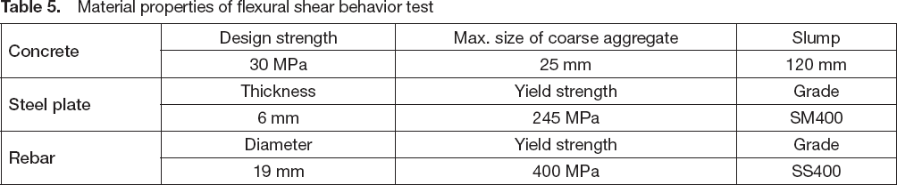
Material properties of flexural shear behavior test
The dimensions of the flexural shear behavior specimen are 1000 mm (the width) × 200 mm (the height) × 3500 mm (the length). The sizes of the Perfobond Rib and Head Stud shear connectors are t6 × 133 mm and

Cross-section of proposed each deck profile
Names of specimens and parameters

As shown in
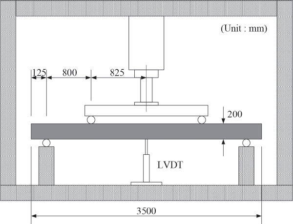
Set-up for flexural test
The test results of the flexural shear behavior specimens are shown in

Breaking of specimen in flexural test

Load-slip of flexural shear specimens
Results of flexure shear test
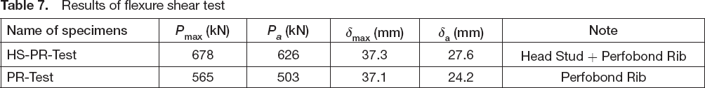
The separation of the bending steel and concrete in the PR-Test specimen made of Perfobond Rib shear connectors only started at the end of the specimen when the load reached 245 kN and showed significant separation and destruction when the load reached 539 kN. The maximum load was 565 kN. The deflection was 37.1 mm at the maximum load. As shown in
In this study, the degree of shear connection of PR-Test and HS-PR-Test specimens was analyzed based on the results of flexural shear behavior. The degree of shear connection was calculated from Equation (1) in accordance with the method suggested in EN 1994-1-1. The larger value of η implies superior composition performance. If η ≥ 1, it is assumed that the composition status is perfect. To calculate the yield strength of the composite slab, the value of shear strength in the longitudinal direction of shear span should first be calculated. With this result, h, the degree of composite, can be drawn with Equation (1). The partial shear bonding moment, Mpsc, can then be calculated. In this study, the degree of steel composition for deck plate variables was indirectly evaluated using the maximum moment, Mmax, instead of Mpsc for the evaluation of the steel-concrete composite deck slab
8
.
Degree of shear connection

Degree of shear connection
In this study, the direct shear resistance performance of Perfobond Rib shear connectors is analyzed and a direct shear stress formula is proposed for the direct load given in Section 3.5 on the basis of such test results. Furthermore, an analysis is performed of the flexural and direct shear stress and the shear stress in the direction of the load, by comparing the direct shear stress formula and the flexural shear stress formula suggested in Section 2.2 (EN 1994-1-1).
Many domestic and foreign studies, including Rui(2008), focus on methods to calculate shear force in the perpendicular direction, called flexural shear force 9 . In this study, the relationship between flexural shear force and direct shear force is analyzed by calculating the flexural shear force using Equation (2), adopting the degree of shear composition (η) suggested in EN 1994-1-1 and comparing the results with the direct shear stress from Equation (4).
According to the calculation of the HS-PR-Test specimens, it is shown that the flexural shear stress is 2.90 kN/mm 2 and the direct shear stress is 2.81 kN/mm 2 . The HS-PR-Test specimen is made of a Head Stud and Perfobond Rib shear connectors. For the PR-Test specimen, the flexural shear stress is calculated as 2.33 kN/mm 2 and the direct shear stress is 2.19 kN/mm 2 . As for existing study results, the flexural shear stress is stronger than the direct shear stress because of the stress redistribution through load steps from the vertical direction to the horizontal direction. Equation (4) suggested in this study does not show clear results for all specimens using Perfobond Rib connectors in each case. However, it is known that general flexural shear stress is similar to, or the same as, direct shear stress through this study.
According to a recent study by Shin (2005), obvious differences are observed between composite behaviors of shear connectors obtained in the standard Push-Out Test and shear composite behaviors occurring in an actual composite beam. Especially, it is revealed that the difference is even greater when a beam is partially composited 10 . This is demonstrated by the fact that a concrete slab of a composite beam in a static moment section is under a higher compressive stress condition than in the standard Push-Out Test. The test result shows that, in some cases, a composite beam designed as a partial shear composition shows actually perfect shear composition behaviors when comparing the designing value with the actual value obtained in the test; this concurs with the above argument.
Conclusions
In this study, specimens were prepared for a direct shear behavior test and a flexural shear behavior test using Perfobond Rib connectors and a comparative test was performed to analyze the results. The following conclusions were made.
According to the direct shear test of the Perfobond Rib shear connectors, the main factors that influence direct shear resistance are the tip resistance of the concrete of the rib, the dowel effect of concrete and the bearing capacity of the traverse reinforced bars. In addition, the concrete dowels can be reduced by overlapping of stress fields as the distance between holes.
For practical application of Perfobond Rib shear connectors, a regression analysis was performed using the results of direct shear strength test. Equation (4), as a formula to assess the direct shear strength of Perfobond Rib shear connectors, was also proposed. According to the results, Equation (4) shows a relatively good fit with less than 10% error. It is found that the most significant cause of the error is the second term, which is related to the dowel effect. This can be considered as an error of the regression analysis. In addition, the effect on the end bearing and the traverse reinforced bars shows a relatively good fit.
Based on the result of the flexural shear test, the degree of shear composition (η) is calculated and the flexural shear stress is drawn. It is revealed that the flexural shear stress is approximately 6% stronger than the direct shear stress, according to the comparison of the flexural stress drawn in this process and the direct shear stress identified in the push-out test.
Footnotes
Acknowledgment
This study was supported by Research Fund of National Research Foundation of Korea(NRF)-2015R1C1A1A02036540. The authors gratefully acknowledge this support.