
Abstract
The microvoid based Gurson-Tvergaard-Needleman (GTN) model is a powerful tool for predicting ductile fracture behavior, and application of such model to steels and welds needs the identification of microvoid related damage parameters. Currently, there is no standard damage parameter identification method available. In this study the previously proposed complete Gurson model (CGM) where a physical void coalescence mechanism is incorporated into the GTN model is revisited. According to the CGM, the void nucleation process dictates ductile fracture. By adopting the cluster nucleation model with an effective initial void volume fraction as the only controlling parameter, a method is proposed to explicitly determine the effective initial void volume fraction from the strain at maximum load and strain at fracture of a specially designed notched tensile specimen. The proposed equation has been experimentally verified by applying to three high strength materials, including a X80 pipeline steel and associated weld metal, and a 15CrMo steel. A general procedure for damage parameter identification is also suggested. It is argued that the obtained effective initial void volume fraction can be treated as a type of material ductility indicator.
Keywords
Introduction
Structural components made of high strength steels may fail by ductile fracture. It is well recognized that ductile fracture of steels results from the nucleation, growth and coalescence of microvoids. The most widely used model for ductile fracture was originally developed by Gurson (1977), and further modified and improved by Tvergaard and Needleman (Tvergaard, 1981, 1982; Tvergaard and Needleman, 1984). The application of this ductile damage model, also well-known as the GTN model, needs the identification of as many as 17 parameters (Zhang et al., 2018), including the material-specific void (nucleation and coalescence) parameters, constitutive parameters, characteristic length parameter(s) as well as other material-independent model parameters. It is a common practice to calibrate the parameters of the GTN model through a combination of experiments and numerical simulations (Sun et al., 1989; Springmann and Kuna, 2005; Abendroth and Kuna, 2006; Seupel et al., 2020; Miloud et al., 2019). Smooth and notched tensile specimens where the stress/strain gradients were not strong and finite element mesh size does not play a significant role, are often used to determine the void parameters (Zhang et al., 2000). When the GTN model is applied to cracked components where severe stress gradient exists in the vicinity of crack tip, the predicted failure becomes mesh size dependent. In such cases, a so-called non-local characteristic length parameter(s) should be considered (Zhang et al., 2018). Fracture mechanics specimens such as compact tension (Acharyya and Dhar, 2008; Dotta and Ruggieri, 2004) single edge notched tension (Chen and Lambert, 2003), single edge notched bending (Qiang and Wang, 2019; Sarzosa et al., 2016), drop weight tear testing (Scheider et al., 2014; Nonn and Kalwa, 2012) have been used for the calibration of both the void and characteristic length parameters either separately or simultaneously. It is interesting to note that machine learning methods have also been recently applied to the identification of GTN parameters (Chen et al., 2021; Ouladbrahim et al., 2021). In order to limit the scope, this study will focus only on the void parameters.
As far as void parameters concerned, it has been noted by Zhang (1996) more than two decades ago that when comparing with a set of experimental results, the fitted GTN damage parameters are not unique. This non-uniqueness problem implies that different combinations of void nucleation and coalescence parameters may lead to indistinguishable macroscopic responses. This non-uniqueness problem may not have severe consequence if the purpose is to simulate the macroscopic behavior of a specific structural component. However, it does have serious implications in terms of the physical interpretation, transferability of the void parameters and classification of materials deformation and fracture behavior based on damage parameters.
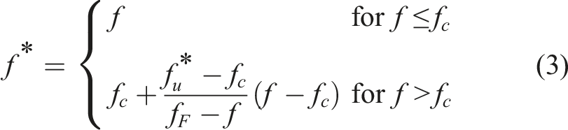
The non-uniqueness problem partly attributes to the lack of a physical void coalescence mechanism in the GTN model which treats the void nucleation and coalescence as two independent events. As a viable solution to the problem, by incorporating a physical void coalescence mechanism based on Thomason’s plastic limit load model (Thomason, 1990) into the GTN model, a so-called complete Gurson model (CGM) has been proposed by Zhang (Zhang et al., 2000). The key feature of the CGM is that the void coalescence is a natural result of the plastic deformation of a material with nucleated voids, and the so-called critical void volume fraction at the beginning of coalescence
In the literature, it has been a common practice to estimate the initial volume fraction
In the following, Section 2 briefly revisits the CGM. Section 3 describes the specially designed notched tensile specimen used. In Section 4, the numerical simulation procedure, the correlation data and the obtained equation to explicitly calculate the
Revisit of the complete Gurson model
The special feature of the complete Gurson model is the introduction of a physically based coalescence criterion. In the following the GTN (Gurson, 1977; Tvergaard, 1981, 1982; Tvergaard and Needleman, 1984) model will be introduced first. The GTN model describes the homogeneous yielding and void growth behavior of a unit cell with a void located in the centre. The yielding function is expressed as:

The application of the GTN model requires the information about the void nucleation process. In general, void nucleation can be cluster-based or of statistical nature (Zhang et al., 2000). The cluster model which usually assumes that the micro-voids are nucleated upon the onset of plastic deformation, is one of the most commonly used models to describe void nucleation for ductile metals. The cluster nucleation model is adopted in this work. The advantage of the cluster void nucleation model is that there is only one controlling parameter, namely the initial void volume fraction

By incorporating the GTN model for void growth and Thomason’s plastic limit load model for void coalescence, the CGM is obtained. It is called “complete” in a sense that once the void nucleation process is known, the CGM now can physically capture the complete void growth and coalescence process without a need of using any artificial void coalescence criterion or constant (Zhang and Niemi, 1994a, 1994b). It is worth emphasizing that in the CGM void coalescence is not determined by the so-called critical void volume fraction
It must be noted that the CGM treats the voids from the nucleation to the end of coalescence as spherical and the void shape change during the plastic deformation is not considered. The interaction between the voids is also neglected. Thomason’s plastic limit load model is not the only one which can be used for describing void coalescence. Other sophisticated coalescence models which consider both plasticity and void anisotropy can be found in (Benzerga and Leblond, 2010).
The “magic” notched tensile specimen for determining both the stress-strain curve and damage parameters
Standard tensile bar specimen used for determining materials’ stress-strain curve has several limitations in terms of the size of specimen required, unpredictable necking position and the need to perform Bridgman correction (Zhang et al., 2002). Notched round bar tensile specimens are good alternatives to the conventional smooth tensile specimen for characterizing material tensile properties. Notched tensile specimens possess several advantages compared with the smooth one. Firstly, unlike the smooth specimen where necking often occurs in a random manner, the necking in the notched specimens always appear at the intended location. This is especially appealing for the case when the volume of the material to be tested is too small for machining a standard tensile specimen, for example the heat affected zone or weld metal in a steel weldment. Secondly, recent studies show that material’s plastic flow stress-strain curve can be conveniently obtained from notched tensile specimens. In particular, there exists a “magic” notched tensile specimen (Tu et al., 2017), from which the load-minimum cross-sectional area reduction curve recorded can be directly converted to material’s equivalent stress-strain or plastic flow stress-strain curve without the need of performing the non-trivial Bridgman correction (Tu et al., 2017, 2018, 2019, 2020).
For a general notched round bar tensile specimen sketched in Figure 1(a), (a) The geometry of the round notched bar specimen used in the numerical analyses and experimental verification, (b) The finite element mesh and boundary conditions used.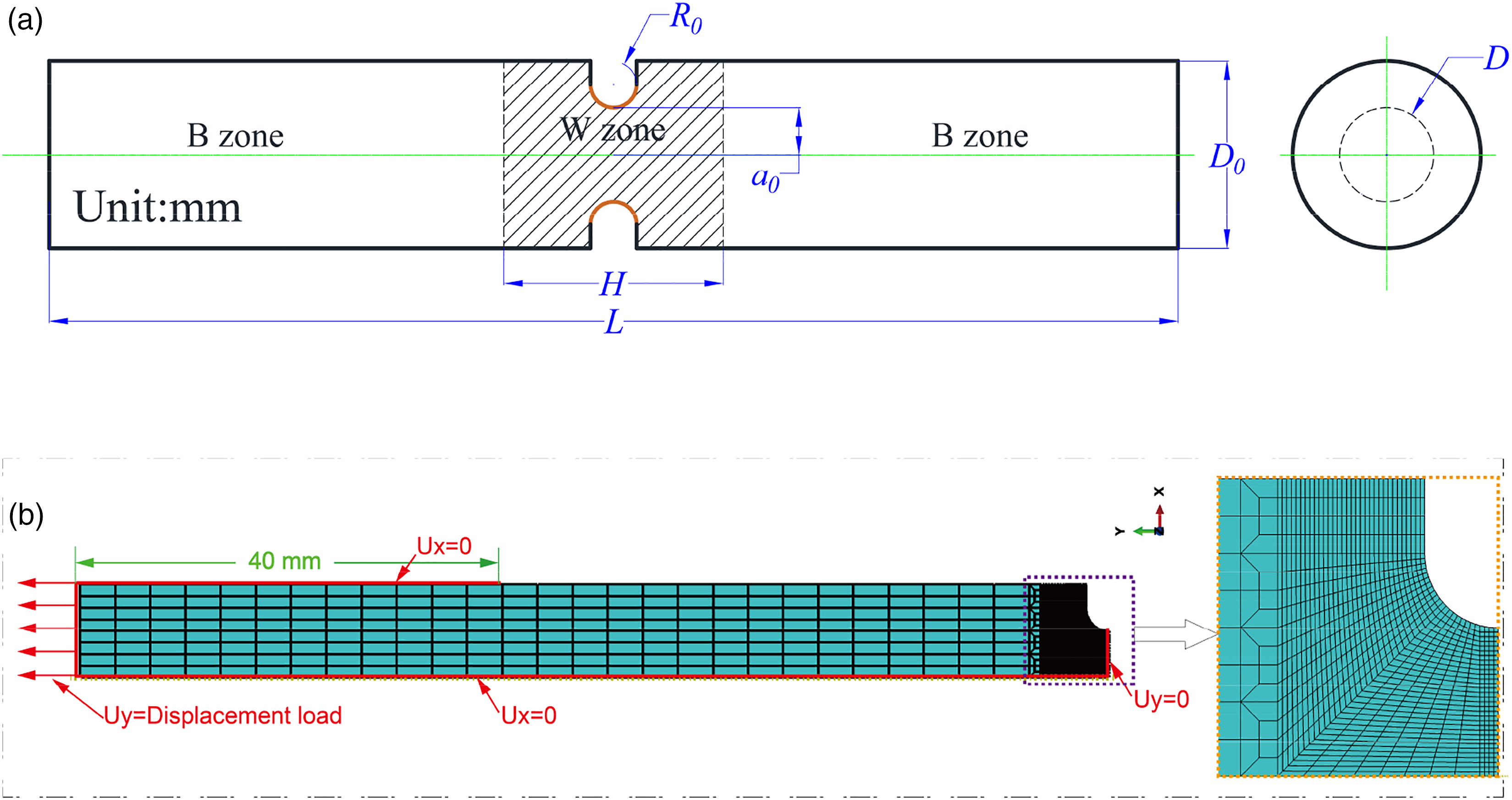
The ratio of minimum cross section radius to notch radius,
Inversely determining the initial void volume fraction
In the following we apply the CGM to analyze the “magic” notched tensile specimen made of materials with different plastic hardening exponents to generate the correlation data between the fracture strain and inputted initial void volume fraction. An explicit equation will be derived to inversely calculate the initial volume fraction from the data points. The obtained initial void volume fraction will then be applied to compare the predicted fracture strains with the experimental values. A recommended procedure to utilize the method for parameter identification is also suggested.
The numerical procedure
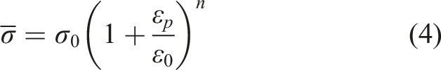
In order to establish the correlation between the inputted damage parameters and the predicted fracture strain, a 1/4 of the axisymmetric notched specimen was modeled with CAX4 element in ABAQUS, as shown in Figure 1(b). The fracture strain was calculated from the predicted cross-sectional area reduction at failure using the CGM. A remote homogenous displacement (clamped boundary condition) was applied at the end of the specimens. The NLGEOM option was activated to take the large-strain effect into account. A general power-law plastic hardening model was used in the parametric study:
The local element size along the middle section was set as Influence of finite element size on the predicted fracture strain by CGM model, (a) for the cases with a fixed 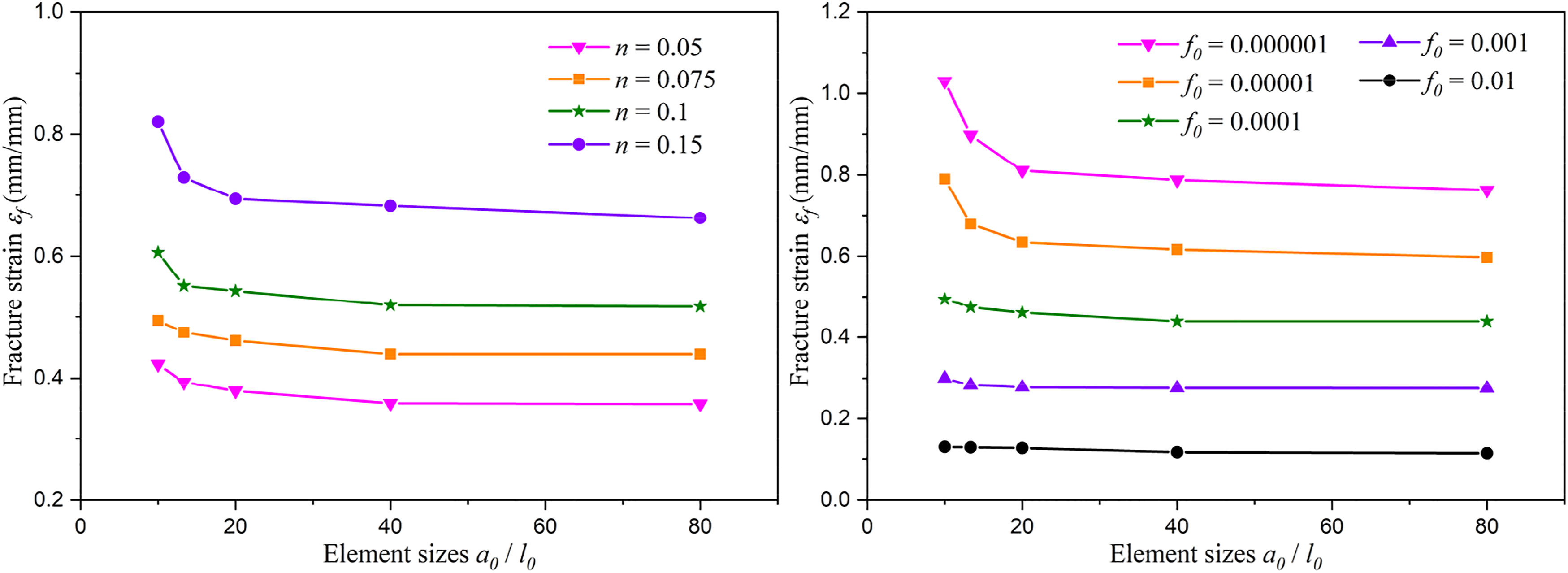
The correlation data and explicit equation
When the CGM is used, the fracture strain of the notched tensile specimen depends on two key factors, the plastic strain hardening exponent

Figure 3(a) shows the predicted fracture strain vs the strain hardening exponent n for the cases with Relationship between the fracture strain and (a) plastic strain hardening exponent 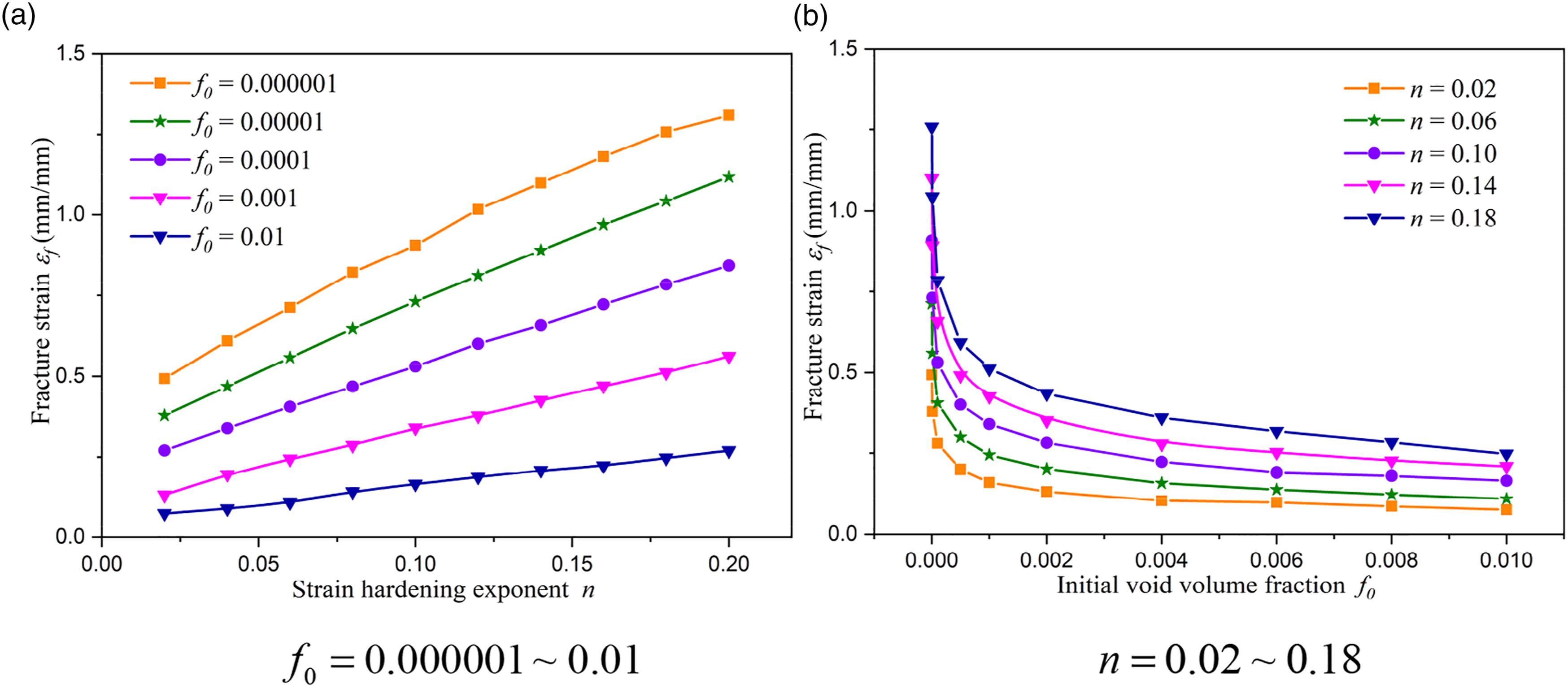
For a given material the plastic hardening exponent

Various forms of equations have been used to fit the correlation data shown in Figure 3. It is found that the data shown in Figure 3 can be best fitted by the following equation:


Figure 4 compares the initial void volume fraction calculated from equation (7) with the original data obtained from the finite element analyses. As can be observed from Figure 4, equation (7) fits the data points quite well. Even for 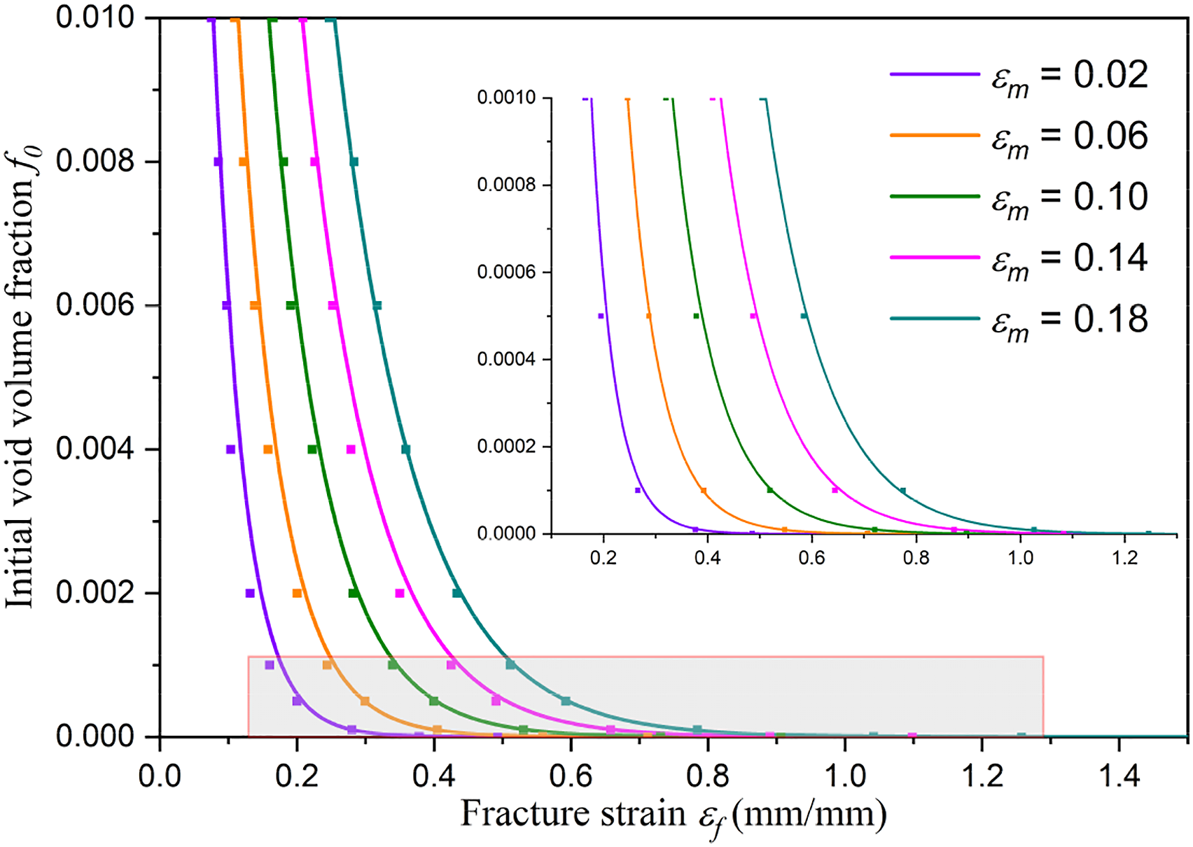
Application to high strength steels and weld metal
The proposed equation (7) for inversely calculating the initial void volume fraction has been verified against three engineering materials with different plastic hardening ability and ductility. The three materials considered are: X80 pipe steel (marked as Specimen 1#), X80 girth weld (Specimen 2#) and 15CrMo steel (Specimen 3#). Specimen 1# and Specimen 2# were derived from a gas pipeline with a diameter of 1016 mm and a wall thickness of 18.4 mm. A total of 9 uniaxial tensile tests using the “magic” notch geometry have been conducted.
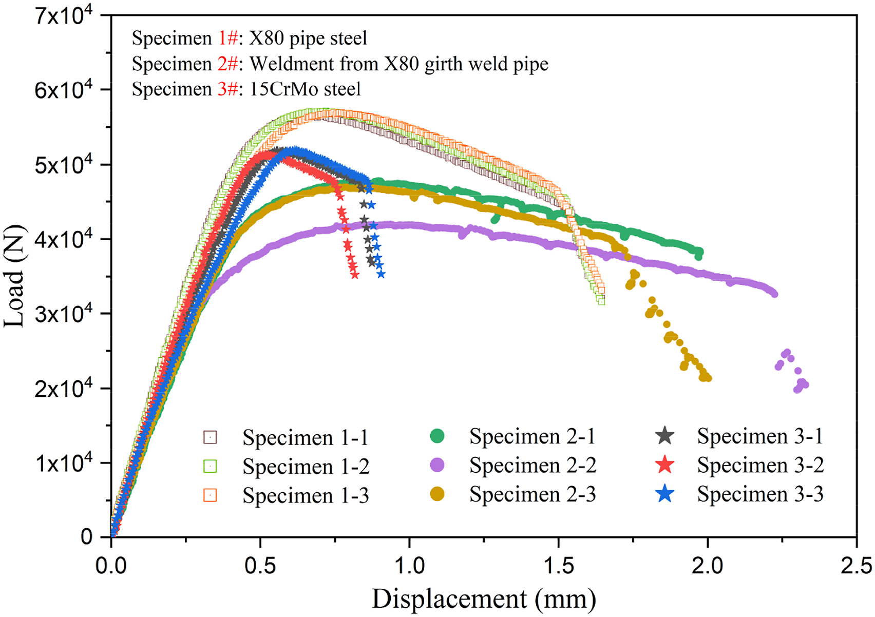
The experimental setup is displayed in Figure 5. The experiments were performed using a MTS 810-25 testing machine. The displacement-controlled mode was adopted, and loading speed was set to be 0.3 mm/min. The load-cross head displacement curves of the 9 specimens are presented in Figure 6. It can be seen that there are relatively small deviations in the load -displacement curves of the X80 steel and 15CrMo steel. As it can be expected, the results of the X80 girth weld (Specimen 2#) shows larger variation in both the load carrying capacity and fracture strain. The experimental setup used for testing of the “magic” notched tensile specimens. Load-cross head displacement curves of the 9 specimens made of three materials.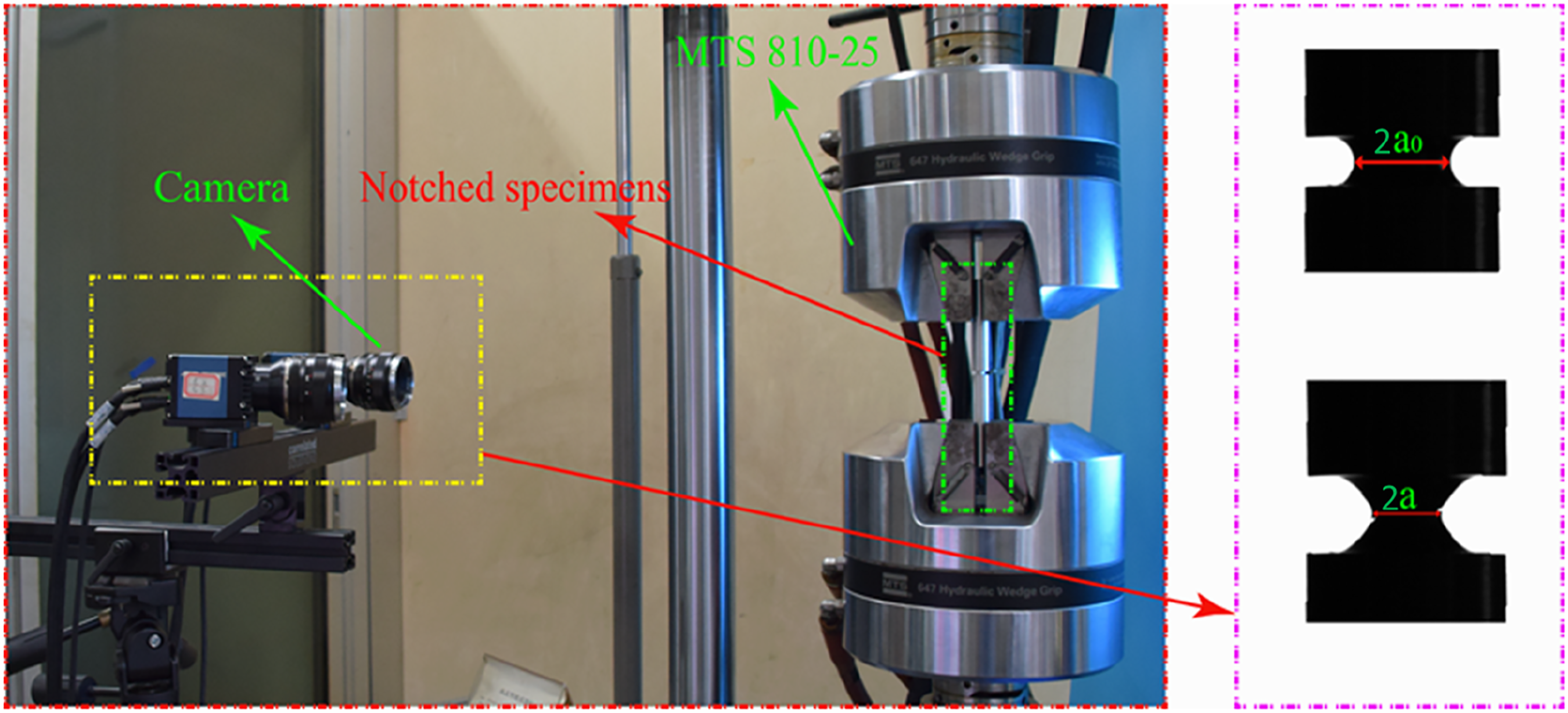
During the tensile testing, the deformations of notched specimens were captured every second by using an industrial digital camera. A python code was developed to retrieve the evolution of the minimum cross section diameter, from which the engineering stress and true strain of the notched tensile specimen can be evaluated. The engineering stress versus true strain curves of the 9 specimens are grouped into 3 figures shown in Figure 7. From these results, the corresponding fracture strain and strain hardening exponent can be identified, and the effective initial void volume fraction is then calculated by applying equation (7). The measured yield stress, hardening exponent and fracture strain together with the calculated initial void volume fraction are summarized in Table 1. It is interesting to compare the X80 weld metal with the X80 base metal. The hardening ability of the weld metal is slightly higher than its base metal, however, the yield stress of the weld metal is significantly lower than that of the base metal and the weldment is a so-called undermatched weldment. Comparison of the experimental engineering stress-true strain curves with the ones from finite element analyses using the data shown in Table 1. The points are from experiments and solid lines from finite element analyses using the initial void volume fraction fitted. (a) Specimen 1-1, 2-1, 3-1. (b) Specimen 1-2, 2-2, 3-2. (c) Specimen 1-3, 2-3, 3-3. Mechanical properties and the inversely calculated initial void volume fraction.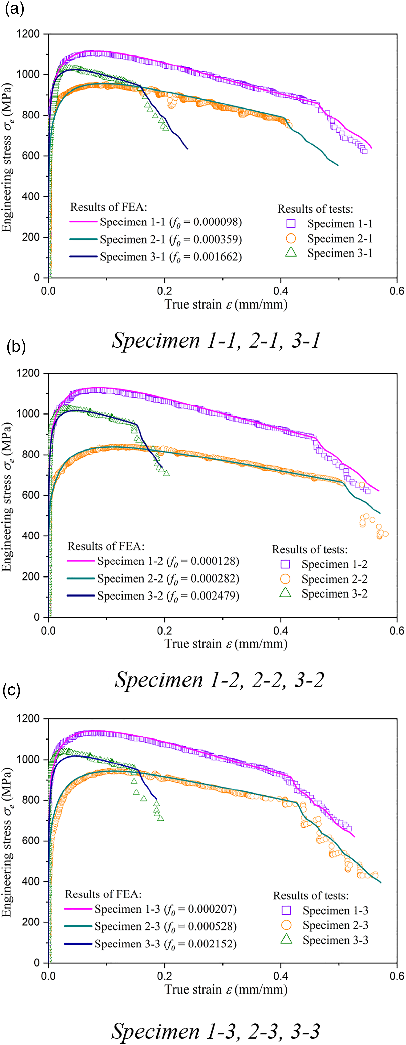
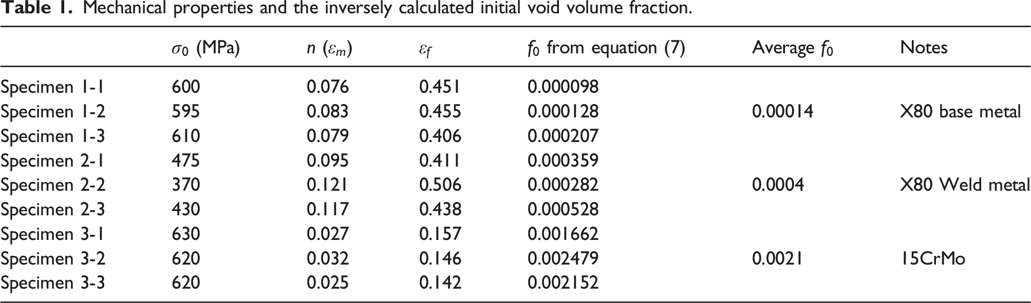
Table 1 shows the inversely calculated average initial void volume fractions for the three materials tested. The X80 steel has the smallest initial void volume fraction, with a mean value between 0.01% to 0.02%. It is interesting to observe from Table 1 and Figure 7 that although the fracture strain of the X80 weld metal is in the similar level of the X80 base metal, the average initial void volume fraction of the weld metal is much higher than, almost 3 times, those of the base metal. Figure 7 also shows that the fracture strain of the 15CrMo steel is the lowest among the three materials tested, and the average initial void volume fraction is approximately 15 times larger than the X80 steel. This finding indicates that the initial void volume fraction of a material is not solely determined by the ductility but is strongly dependent on the plastic strain hardening ability. For materials with identical fracture strain, the material with higher hardening ability will yield larger initial void volume fraction.
We note that the equation (7) was obtained based on the analysis of the ideal power-law hardening materials. It is interesting to verify that the application of the initial void volume fraction calculated from equation (7) will result in the same ductile fracture behaviour of the engineering materials. The measured yield stress and plastic strain hardening exponent and the initial void volume fraction shown in Table 1 have been taken as inputs to the finite element analyses, and the outputs from the finite element analyses have been compared with the experimental results in Figure 7. The comparison shows that the finite element results are in well accordance with the test results, especially the prediction of fracture strain is captured quite accurately. The good agreement confirms that the validity of equation (7).
Recommended procedures for identifying initial void volume fraction
In this work an explicit equation, equation (7), for inversely determining the initial void volume fraction for a given material is obtained. It has been shown that the equation possesses a good accuracy for the materials tested. Following recommended procedure is suggested. (1) Prepare the “magic” notched tensile specimen as shown in Figure 1(a). It is particularly important that the notch geometry fulfils the requirement (2) Perform uniaxial notched tensile tests. Both the applied load and the reduction of the minimum cross section diameter should be measured. Unlike the smooth tensile specimen, the elongation within a gauge length is not useful for the notched tensile specimen. (3) Sketch the engineering stress-true strain curves of the notched tensile specimen ( (4) Compute the initial void volume fraction
When equation (7) is applied to the case where the volume of material of interest (weld metal or heat affected zone in a weldment) is limited, the zone size of the homogenous material to be tested should be as large as possible compared with the minimum cross section diameter
Discussion and conclusions
The “magic’ notched tensile specimen has been shown previously to possess a special function, namely, the true stress-strain curve obtained from the tensile test using this special specimen can be directly converted into materials equivalent stress-strain curve without the need of performing a Bridgman correction. This study extends the function of the “magic” notched tensile specimen to determine the ductile damage parameter – the initial void volume fraction
It is important to emphasize that the obtained the initial void volume fraction physically represents the effective initial void volume fraction of the tested material. The obtained effective initial void volume fraction ideally can be treated as a material ductility indicator, and transferred to the other cases with different stress triaxiality. However, the transferability may be material specific and remains to be experimentally verified in the near future. Only one notch geometry was considered in this study. Similar equations for other notched tensile specimens can be derived using the same procedure reported in this study. When the effective initial void volume fractions obtained from two notched tensile specimens differ significantly, question regarding the choice of the cluster void nucleation model should be raised. If that is the case, other void nucleation models, such as continuous void nucleation or statistical nucleation model may be considered [27]. There is only one parameter associated with the continuous void nucleation model. However, more than one parameter must be involved in the statistical void nucleation model. A good advice is to fix as many parameters as possible and leave only one parameter to be identified.
In summary, based on the CGM model and by adopting a cluster void nucleation model and assuming that the void nucleation can be described by an effective initial void volume fraction, an explicit equation to calculate the effective initial void volume fraction using a special notched tensile specimen is presented. A recommended procedure for using the method is proposed. The method is particularly applicable to the cases where the size of the material zone of interest is limited, and it is impractical to machine the material to fabricate standard specimens for mechanical characterization. The method has been verified against three engineering materials including two types of high strength steels and one weld metal. It is expected that the method will facilitate the identification of damage parameters.
Highlights
• A method is proposed to explicitly calculate the effective initial void volume fraction from the strain at the maximum load and the strain at fracture of a specially designed notched tensile specimen. • The method is well-suited for weldments where material volume of homogenous microstructure is limited. • The proposed method has been experimentally verified by applying to three engineering materials including both high strength steels and an associated weld metal. • This effective initial void volume fraction can facilitate the classification of deformation behavior of metallic materials.
Footnotes
Acknowledgements
The first author also wants to thank the Chinese Scholarship Council (CSC) for the financial support. Z. Zhang wants to thank the support from the Research council of Norway via the M-HEAT project (Grant No. 294689).
Declaration of conflicting interests
The author(s) declared no potential conflicts of interest with respect to the research, authorship, and/or publication of this article.
Funding
The author(s) disclosed receipt of the following financial support for the research, authorship, and/or publication of this article: This work was supported by the China Scholarship Council, Norges Forskningsråd (294689) and Natural Science Foundation of China (51874324).