
Abstract
The paper presents a novel family of strain-based beam finite elements (FE) for analysis of tensile failure of a reinforced concrete bar (RC bar), with results of the analysis being independent of the applied FE mesh. The composite bar consists of a continuous longitudinal ductile reinforcing bar(s) surrounded by brittle concrete cover, which are considered separately in the model. Longitudinal slip at the contact between the concrete cover and reinforcing bars is allowed, while their relative displacements perpendicular to the axis of the RC bar are prevented. Cracks in concrete cover occur when tensile stress in concrete exceeds its tensile strength. Propagation of partially connected crack, that is, softening of the material at the crack, is described through constitutive law in form of nonlinear relationship between stresses in concrete at the crack and the width of the crack. Each separate crack is considered discretely as a discontinuity in geometry of the element. In the analysis of cracking of concrete, it is commonly assumed that the discrete crack can occur at the nodes of FE only. However, this assumption leads to dependence of the analysis results on the employed FE mesh. The presented family of FE enables occurrence of the crack anywhere along the FE. In order to achieve this, the discrete crack is excluded from equations of FE and additional boundary conditions are introduced at the discontinuity. This approach ensures that the location of the cracks, their number and their propagation are independent of the applied FE mesh. Advantages of the novel family of FE are thoroughly presented in a parametric study which investigates influence of number of FE as well as influence of degrees of interpolation and integration on the cracking of RC bar under tensile loading. Experimental results of tensile tests on the analysed bar are available in literature. It can be concluded that the results obtained with the minimal possible number of novel FE and sufficiently high degree of numerical integration scheme, applied for solving integrals in equations of FE, are considerably more accurate than the results of previous analyses with model of discrete crack at the nodes of FE only.
Keywords
Introduction
Concrete is a heterogeneous and brittle material, where even very small tensile loading can result in occurrence of cracks. Cracking of concrete significantly influences stiffness, ductility and strength of reinforced concrete (RC) structures; therefore, its consideration is essential for realistic mechanical analysis of such structures. Currently, there are two established advanced models of concrete cracking, both based on the principles of fracture mechanics. Cracking of concrete in the first model is considered through occurrence of discrete cracks (e.g. in Bajc et al., 2013; Dias-da-Costa et al., 2009; Federation internationale du beton, 2013; Yang et al., 2008 and others). When the tensile strength of concrete, fct, is exceeded, a discontinuity in the geometry of the element occurs (see Figure 1(a)). The next phase in the process of crack opening is when both parts of concrete cover at the crack are still connected by aggregate grains (Cerioni et al., 2011). This phenomenon of partial connection through aggregate grains is in scientific literature known as aggregate bridging. The constitutive law of crack propagation is defined through mutually related tensile stress in the crack, σr, and the width of the crack, r. Several researchers formulated the law as a bilinear relationship (e.g. Federation internationale du beton, 2013; Rabzcuk et al., 2005), while others employed the form of exponential function (e.g. Carpinteri, 1999). Fracture energy of concrete, Gf, is a material parameter introduced in the constitutive law of crack propagation, which describes entire work required for failure of cracked part of concrete cover and equals the area under σr-r curve (see Figure 1(a)). Bilinear constitutive law of crack propagation depicted in Figure 1(a) is taken from Rabzcuk et al. (2005). The limit value of the crack width, r = wcrit, reached when σr decreases to zero, is calculated through given equation. Here, the parameter αt is a constant and equals 0.14, while the parameter βt depends on compressive strength of concrete, fc. When cracks are considered to be discrete, that is, as discontinuities in the geometry of the elements, the structure is usually analysed with finite element method and appearance of cracks is limited to nodes of the elements. Therefore, in order to achieve sufficiently accurate results of crack propagation analysis, which are independent of finite element mesh, sufficiently dense finite element mesh must be employed. Lately, mesh-free methods, such as free Galerkin method (see e.g. Rabzcuk et al., 2008; Yang et al., 2008), have proven to be a promising alternative to the finite element method. Constitutive law of propagation of a discrete and a smeared crack.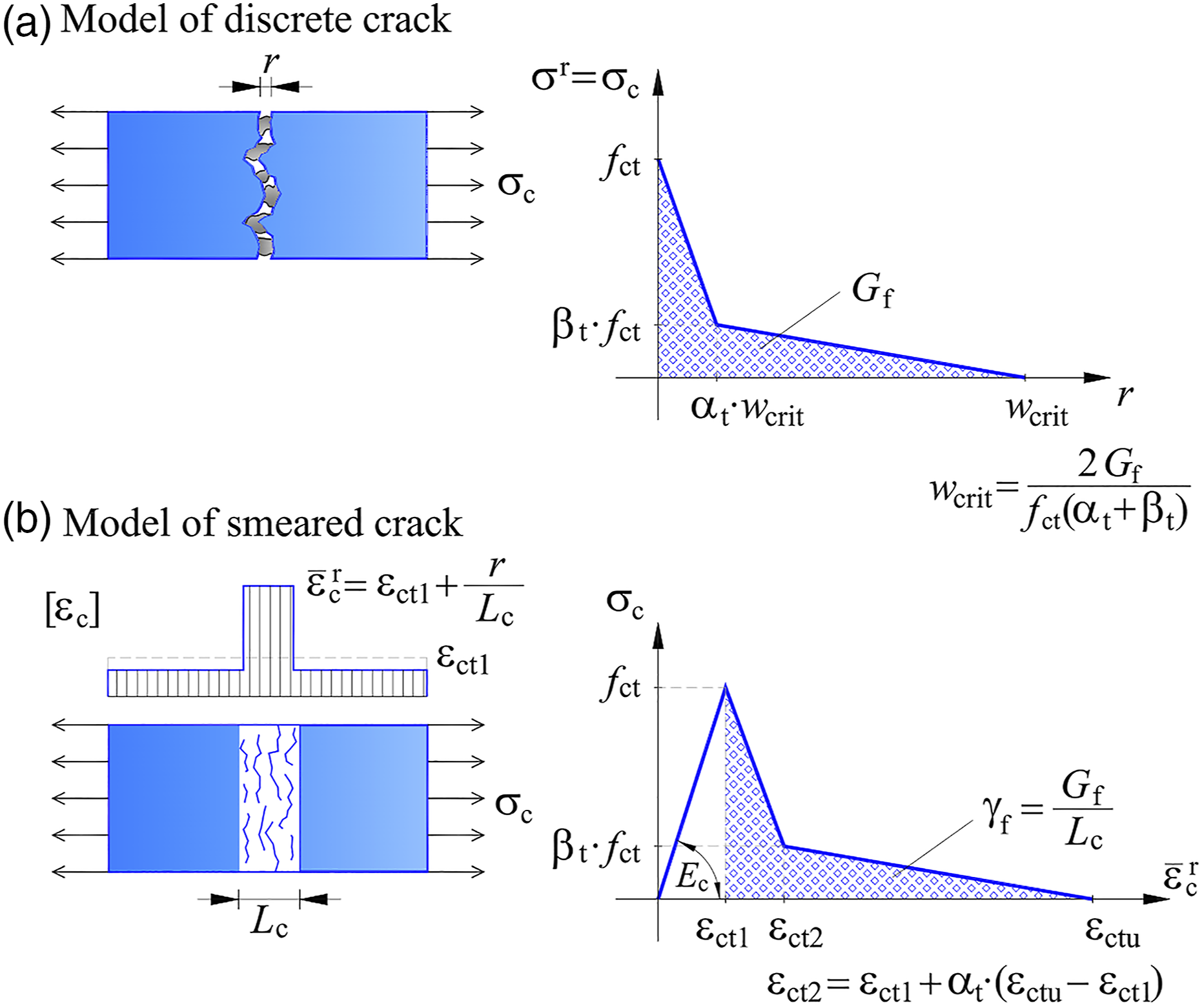
The second model considers cracking of concrete in a form of so-called smeared cracks, where the distribution of cracks is not realistic, as presented in Figure 1(b) (see Bažant and Pijaudier-Cabot, 1989; Bažant and Planas, 1997; Federation internationale du beton, 2013; Yang et al., 2008 and others). When the tensile strength of concrete is exceeded, localisation of extensional strains in concrete, ɛc, occurs on a band of the element with limited length, Lc, as shown in Figure 1(b).The length of this band of concrete, over which the cracks are smeared, is not arbitrary. Instead, it must be defined as a material parameter and depends on fracture energy of concrete, Gf, and constitutive law of crack propagation. The latter is here defined through tensile stress, σc, and localized extensional strain,
For the study of occurrence of cracks in concrete cover as well as their propagation, RC bar with tensile load is most convenient. The RC bar is composed of continuous longitudinal reinforcing bar and of enveloping concrete cover. Tensile load can be applied through reinforcing bar, if it continues outside of the concrete cover, or through the concrete cover itself. For the analysis of concrete cracking, it is essential, that cracks in concrete cover appears prior to plastification of reinforcing bars. In order to meet this requirement, the area of cross-section of concrete cover must be sufficiently small (see e.g. Wollrab et al., 1996). The paper presents a novel family of strain-based beam finite elements for analysis of tensile failure of RC bar. The main advantage of the novel finite element is that positions, number and development of discrete cracks are independent of the applied finite element mesh. Furthermore, very good analysis results are obtained with the smallest possible number of finite elements.
In the novel method, cracks occur at so-called ‘excluded’ points anywhere along the length of the finite element, with the only criterion for its occurrence being exceeded tensile strength of concrete. The key criterion for the assessment of suitability of novel finite elements is that the position and number of cracks, together with the rest of physical quantities do not vary significantly with an increase of number of finite elements.
Numerical model of RC bar with discrete crack at ‘excluded’ point
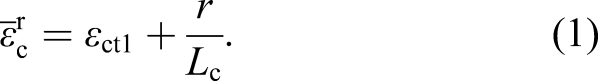
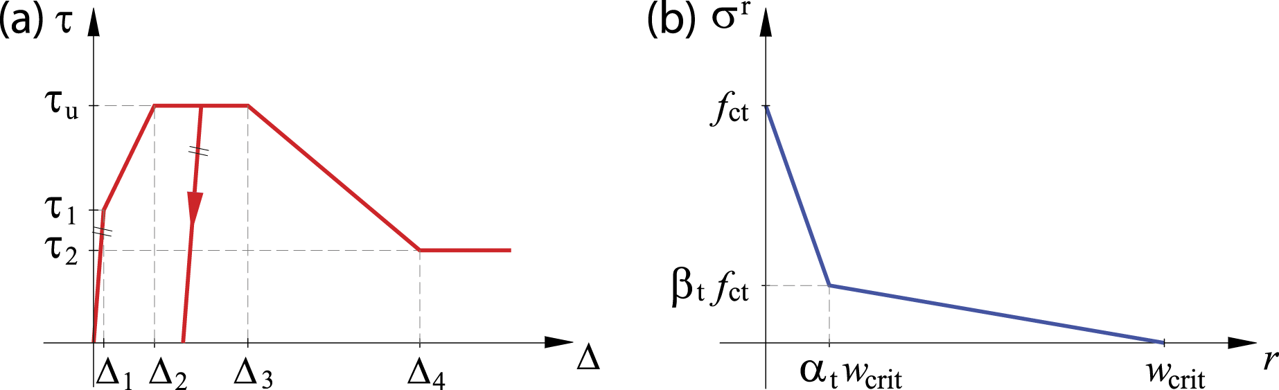
The numerical model is presented on an example of RC bar with only one reinforcing bar with diameter ϕ and area of cross-section As. The reinforcing bar is positioned in the centroid axis of the concrete cover with cross-section Ac. A RC bar, cracked due to the application of external tensile load, is schematically presented in Figure 2. Its initial length is L, while L′ denotes the length of the deformed and cracked bar. Basic assumptions of the model are: 1. the size and the shape of the cross-section of the concrete cover as well as of the reinforcing bar do not change during the deformation; Bernoulli’s hypothesis of planar cross-sections is assumed; 2. the concrete cover and the reinforcing bar are modelled separately; deformations of both parts are limited to longitudinal direction; the influence of the radial pressure exerted by the reinforcing bar on the surrounding concrete is neglected; 3. only the longitudinal slip at the contact between the concrete and reinforcing bar is allowed; the slip law is described through relationship between bond stress τ and relative longitudinal displacement at the contact Δ (see Figure 3(a)); the law is multi-linear with possibility of isotropic hardening; 4. concrete in tension is assumed to be linear elastic material with elastic moduli Ec until cracking occurs; the reinforcing bar is made of bilinear elasto-plastic material with elastic moduli Es and yield strength fy; 5. the crack in concrete cover occurs when the stress in concrete reaches its tensile strength fct; 6. opening/closing of the crack is described in the same way as it is described in the model with discrete crack, that is, with constitutive law of crack propagation in form of relationship between tensile stress in the crack, σr, and width of the crack, r (see Figure 1(a) or Figure 3(b)); 7. only one crack per each separate strain finite element can occur. Uncracked and cracked RC bar. Locations of characteristic points. Constitutive law of (a) bond slip (Comite Euro-International Du Beton and Federation International De la Precontraint, 1993) and (b) crack propagation (Rabzcuk et al., 2005).
Hereinafter, governing equations of a RC bar subjected to tensile load previous to crack occurrence are presented first.
Governing equations of a RC bar previous to cracking
Governing equations of the uncracked RC bar, depicted in Figure 2(a), are taken as in Bajc et al. (2018) and include kinematic, equilibrium and constitutive equation, separately for concrete cover and for reinforcing bar, as well as three constraining equations: 1. Concrete cover 2. Reinforcing bar 3. Constraining equations


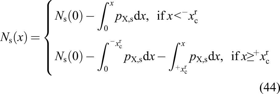
Herein, prime ()′ denotes a derivative of certain quantity with respect to material coordinate x. Longitudinal displacements of reference axis of concrete cover and reinforcing bar are denoted with uc and us, respectively, while ɛc and ɛs are inherent extensional strains of reference axes. Nc and Ns are equilibrium axial forces, while
The constraining equations address longitudinal slip and shear flow at the contact of concrete cover and reinforcing bar. pX,c and pX,s denote shear components of contact line load in concrete cover and in reinforcing bar (shear flow), respectively, whereas
Along with nine governing equations (2)–(10) for nine unknown functions (namely uc, us, ɛc, ɛs, Nc, Ns, pX,c, pX,s and Δ), the corresponding boundary conditions, either static or kinematic, must be given. Boundary conditions at both ends of the concrete cover are


RC bar with one crack
A crack in concrete cover occurs when the tensile strength of the concrete, fct, is reached. After the appearance of the crack, aggregate grains can still connect both ends of the crack, which is a phenomenon also known as aggregate bridging (see Cerioni et al., 2011; Yang and Chen, 2005; and others). This partial connection of concrete cover with aggregate grains applies only when the crack is sufficiently small (r ≤ wcrit). Crack propagation is defined in the form of relationship between tensile stress in the crack, σr, and its width, r, as it was already stated in the list of basic assumptions of the model (see Figure 3(b)).
We assume that the crack occurs in concrete cover at material coordinate Distribution of characteristic quantities along the length L of the RC bar after appearance of the first crack.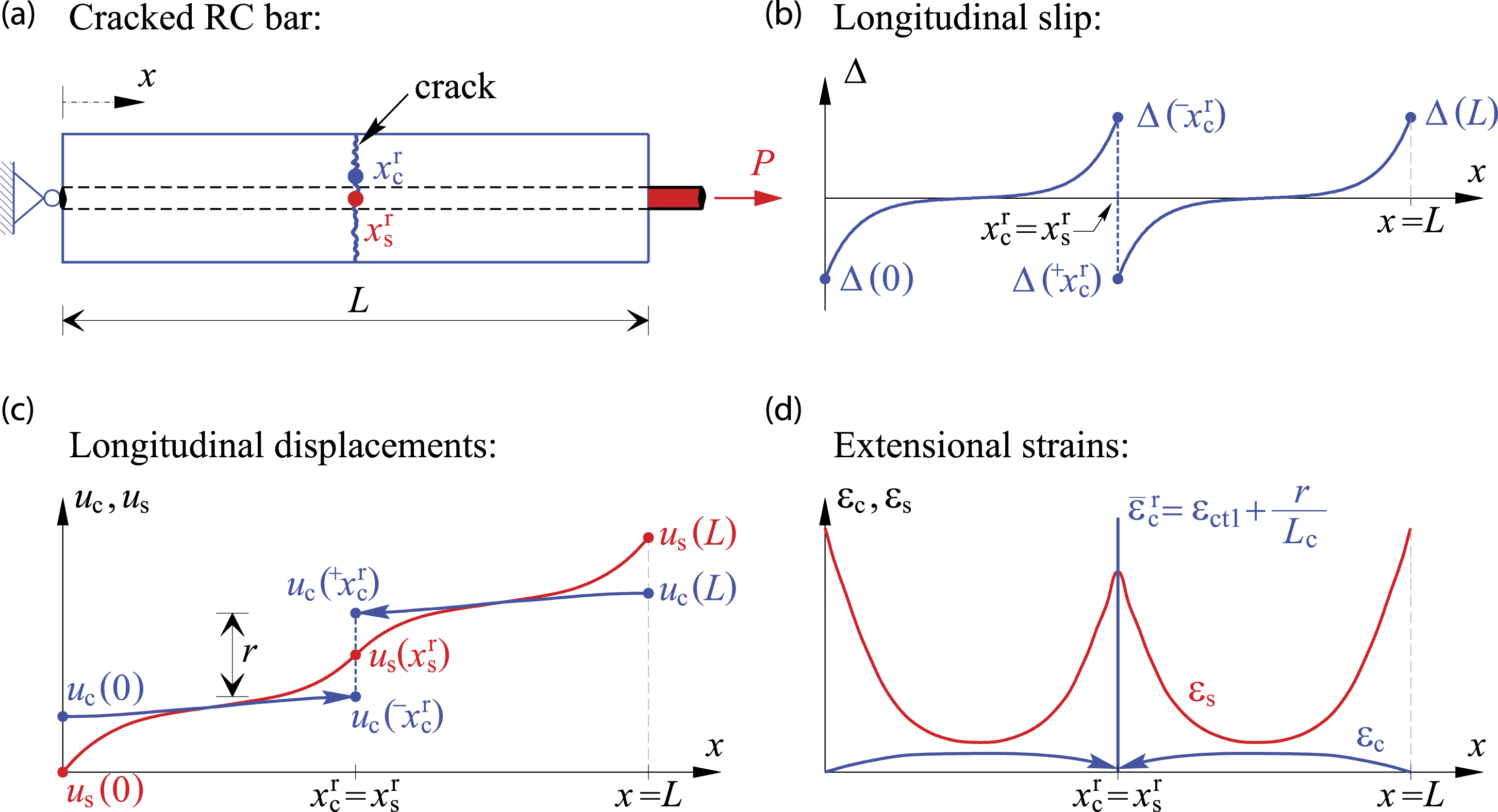


Note, that the characteristic quantities along RC bar after appearance of the first crack in Figure 4 are depicted with respect to the undeformed length of the bar L.
The uncracked concrete cover to the left and right of the crack, that is, at intervals


Finite element formulation
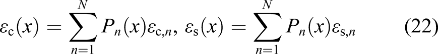
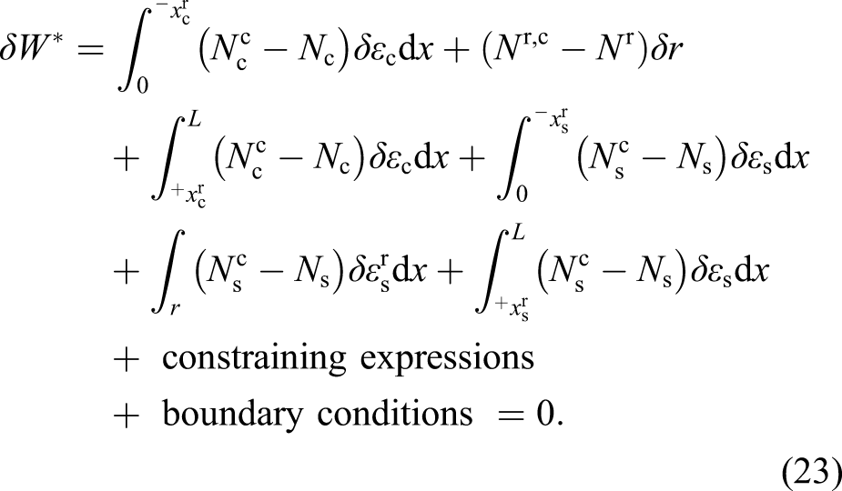
The novel family of strain finite elements is derived hereinafter on a basis of modified principle of virtual work, written for entire RC bar with one crack. Note, that the discrete crack is considered as an ‘excluded’ point of the finite element. However, a system of discrete generalized equilibrium equations of finite element without crack is briefly presented first. This system of equations is applicable in the model of RC bar with discrete crack at ‘excluded’ point previous to cracking, and has already been presented in detail by Bajc et al. (2013, 2018).
RC bar previous to cracking
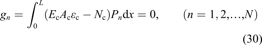
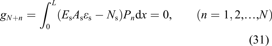
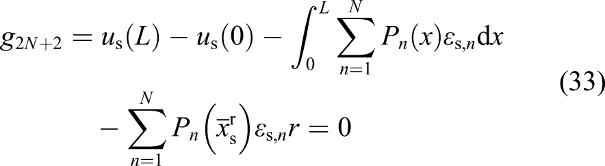
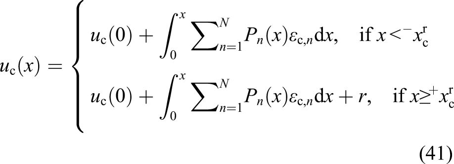
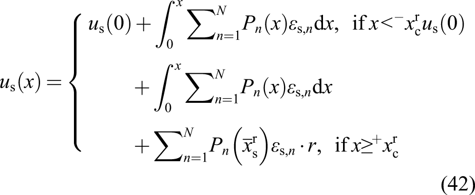
The system of discrete generalized equilibrium equation of uncracked RC bar with tensile load can be found in Bajc et al. (2018). Therefore, the equations themselves are not written down in the present paper, only their most important characteristics are presented. The system consists of 2N + 6 algebraic equations and the same number of unknowns, where 2N + 2 of them are internal degrees of freedom, namely, ɛc,n, ɛs,n, Nc(0), Ns(0), and four of them are external degrees of freedom, namely, uc (0), us (0), uc(L) and us(L). Here, ɛc,n and ɛs,n are strain quantities at nth equidistant points along concrete cover or reinforcing bar (n = 1, 2, …, N). Axial deformation of reference axis of concrete cover, ɛc, and of reinforcing bar, ɛs, are then approximated with Lagrangian polynomials P
n
(x) of N − 1th order
Modified principle of virtual work for a RC bar with one crack
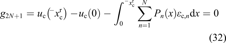
Principle of virtual work states that virtual work of internal forces equals virtual work of external forces. Here, we begin with modified principle as it is given in Bajc et al. (2013, 2018) for RC bar with discrete cracks at nodes of finite element, however, applicable adaptations for RC bar with discrete crack at ‘excluded’ point (at material coordinates 1. Constraining expressions regarding left and right end of concrete cover 2. Constraining expression regarding reinforcing bar
Here,
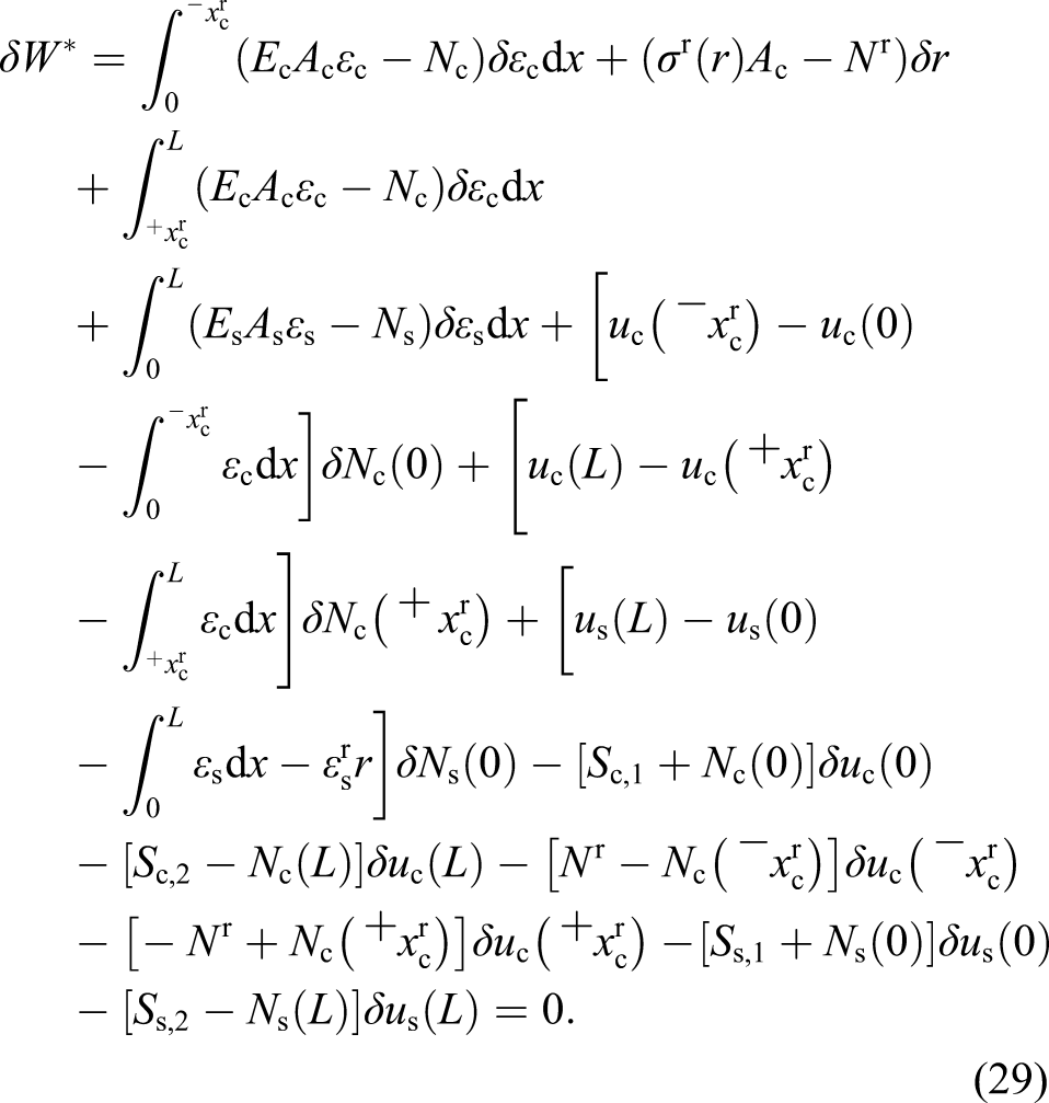
The only two unknown functions in the expression for δW* are axial deformations of concrete cover and of reinforcing bar (ɛc and ɛs). The remaining unknown quantities in equation (29) are represented by their boundary values only. Axial deformations of reference axis of concrete cover, ɛc, and of reinforcing bar, ɛs, are interpolated with Lagrangian polynomials P
n
(x) (n = 1, …, N) of N − 1th order. The same formulation as per finite element prior to crack occurrence applies (see equation (22)). Expressions in equation (22) are used in derivation of expressions for variations of strain quantities δɛc and δɛs, which are then inserted in equation (29). The expression at variation δr is assumed to be identically satisfied, hence, Nr = σr(r)Ac. Furthermore, the expressions at independent variations δɛc,n, δɛs,n, δNc(0), δNs(0),


Again, all integrals in equations of finite elements are evaluated numerically with the Lobatto or Gauss integration scheme.
To sum up, the occurrence of the crack in finite element leads to increase of the system of discrete generalized equilibrium equations from 2N + 6 to 2N + 9 degrees of freedom. At the same time, the forms for interpolation of deformations ɛc and ɛs, as well as the integration schemes, remain unchanged. Since the crack can occur in any of finite elements along the RC bar, with the only criterion for its occurrence being reached tensile strength of concrete cover, we denote all finite elements with unanimous denotation
Solving algorithm
A RC bar is now modelled with arbitrary finite element mesh. Symbol EL stands for the number of finite elements, and symbol NOD = EL + 1 for a number of nodes. In the finite element, where the crack appears during the numerical analysis, the equations for cracked finite element (as presented in previous sections of this paper) are applied. In the remaining finite elements, the equations for un-cracked finite element (as in Bajc et al. (2013; 2018)) are used. All equations are then combined into the equation of system through well established procedures of numerical theory of structures

Appropriate computer programme for analysis of cracked RC bar was developed in software environment Matlab (The MathWorks, Inc. (2016)). Elements of tangent stiffness matrix of finite element both with and without crack were derived analytically and their exactness was checked with software tool Mathematica (Wolfram Research, Inc. (2017)).
Parametric study on accuracy of the introduced strain finite element
Suitability and accuracy of the novel family of strain finite elements are hereinafter presented on example of numerical analysis of tensile failure of RC bar. Characteristics of the bar as well as applied boundary conditions are consistent with experimental data on tensile test from literature (Wollrab et al. (1996)). The same RC bar has already been analysed by Bajc et al. (2018) with their model of discrete cracks in nodes of finite elements.
Geometrical, material and loading data of the analysed reinforced concrete bar
A RC bar with rectangular cross-section b/h = 12.7/5.08 cm and with initial length L = 63.5 cm is analysed. The bar is reinforced with seven reinforcing bars with diameter 6 mm, which are evenly distributed along the middle of the cross-section, as depicted in Figure 5. Experimental results of tensile test were presented by Wollrab et al. (1996). The load on the tested bar was applied to concrete cover through steel fixtures at both ends of the bar. Two notches, each 2 mm wide and 10 mm deep were made at x = L/2 along the shorter sides of the bar, so as to impose the assumed location of the crack. Above each notch, an extensometer with a gauge length le = 1.27 cm was installed, in order to measure relative displacements Geometrical, material and loading data of the analysed RC bar (Wollrab et al., 1996).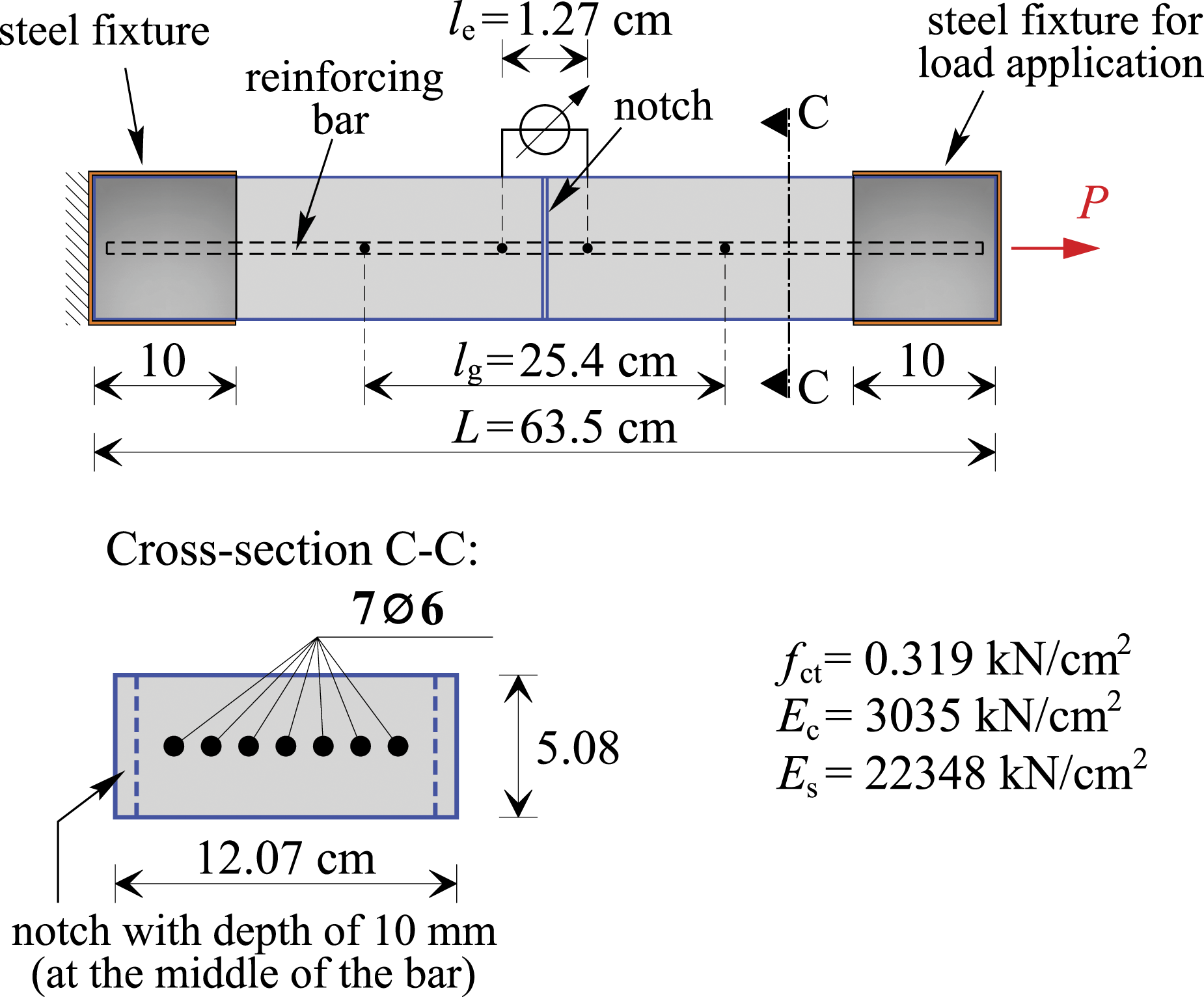
Analysis of concrete cracking of Wollrab RC bar using novel finite element with discrete crack at ‘excluded’ point
For the analysis of cracked RC bar with model of discrete crack (Bajc et al., 2018), where cracks can occur at nodes of finite element mesh only, 48 finite elements were used for modelling of the central part of the bar (i.e. between the steel fixtures), as presented in Figure 6(a). For the present numerical analysis, the central part of the bar is modelled with nine finite elements of type Comparison of the results: (a) numerical model and finite element mesh, (b) computed distribution of cracks in stable state.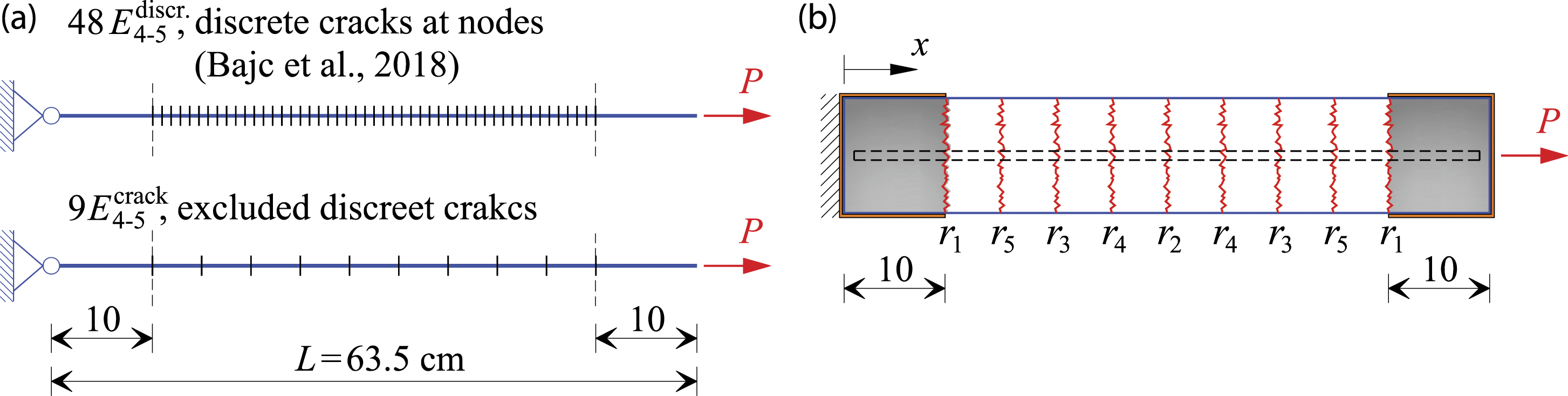
Numerically and experimentally determined elongations of the RC bar in the middle of the bar over the length lg = 25.4 cm in dependence of tensile load P are compared in Figure 7(a). The results of both numerical models are almost identical, which has been expected, since both models employ the same equations but differ importantly in the applied method of calculation. Furthermore, Figure 7(b) depicts comparison of calculated and measured relative displacements of RC bar at the location of the notch in the middle of the bar. Again, very similar results of both numerical models can be observed.The model with discrete crack (Bajc et al., 2018) requires relatively large number of finite elements, depending on the number of cracks and their positions. On the other hand, the novel family of strain finite elements for analysis of tensile failure of RC bar, where the crack can occur at ‘excluded’ point anywhere along the length of the finite element, gives almost identical results with the smallest possible number of the elements (i.e. one element per one crack). The main advantage of the novel family of finite elements, which is independence of numerical results of the prescribed finite element mesh, is thoroughly presented hereinafter. Comparison of the numerical results with experimental results from literature: (a) load–displacement curve on the length lg, (b) load–displacement curve on the length le.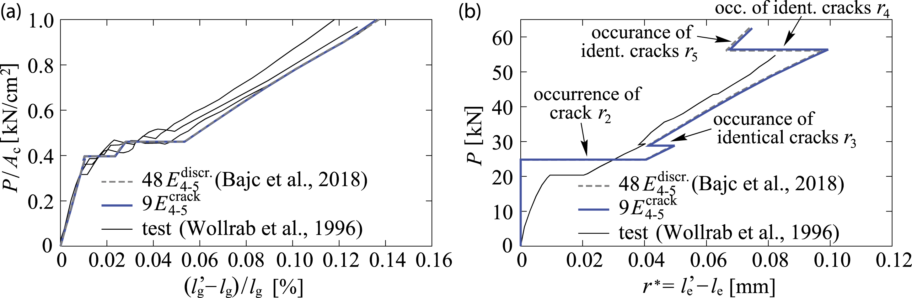
On accuracy of novel family of finite elements
In the parametric study on accuracy of novel family of strain finite elements, the same RC bar as in previous section is analysed. The central part of the bar between the steel fixtures is here modelled with various numbers of finite elements (5, 9, 15, 30, 60 and 100) with equal lengths and of various element types Considered finite element meshes.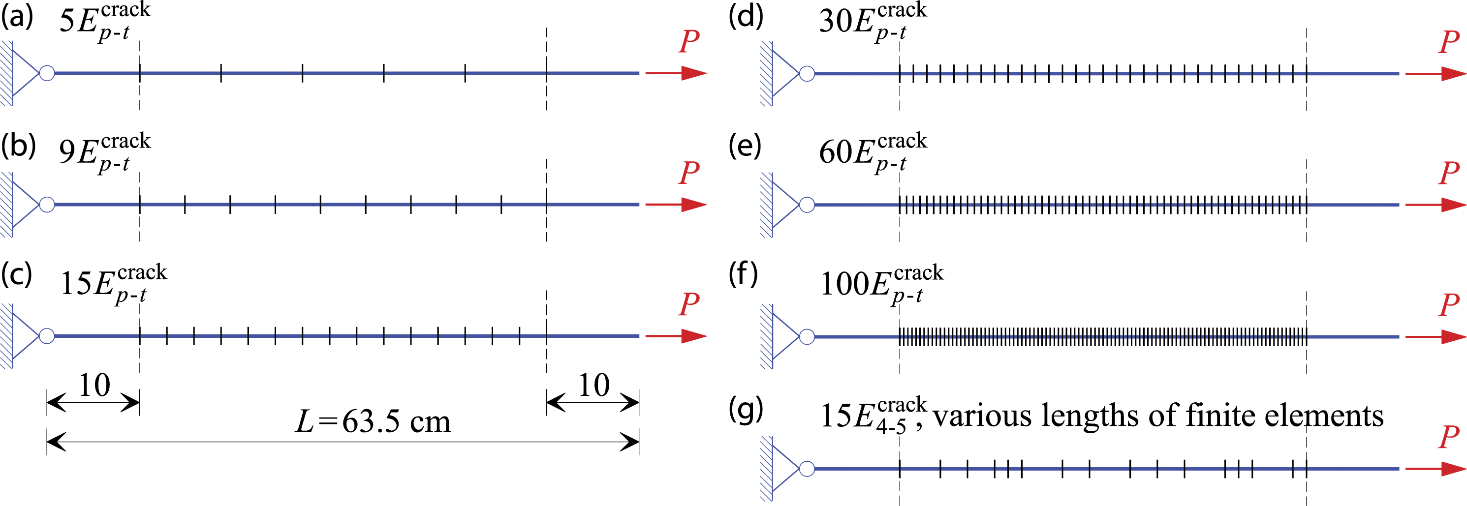
Influence of number of finite elements
First, state of the bar immediately after the occurrence of the crack r2 at the location of the notch in the middle of the RC bar is analysed (see Figure 6(b)). Influence of number and type of the finite elements on elongation of concrete cover of RC bar (Δuc = L′ − L) is presented in Figure 9(a), while Figure 9(b) depicts influence of number and type of the finite elements on the width of the crack r2. The chosen reference values are numerical results obtained with 100 finite elements of type
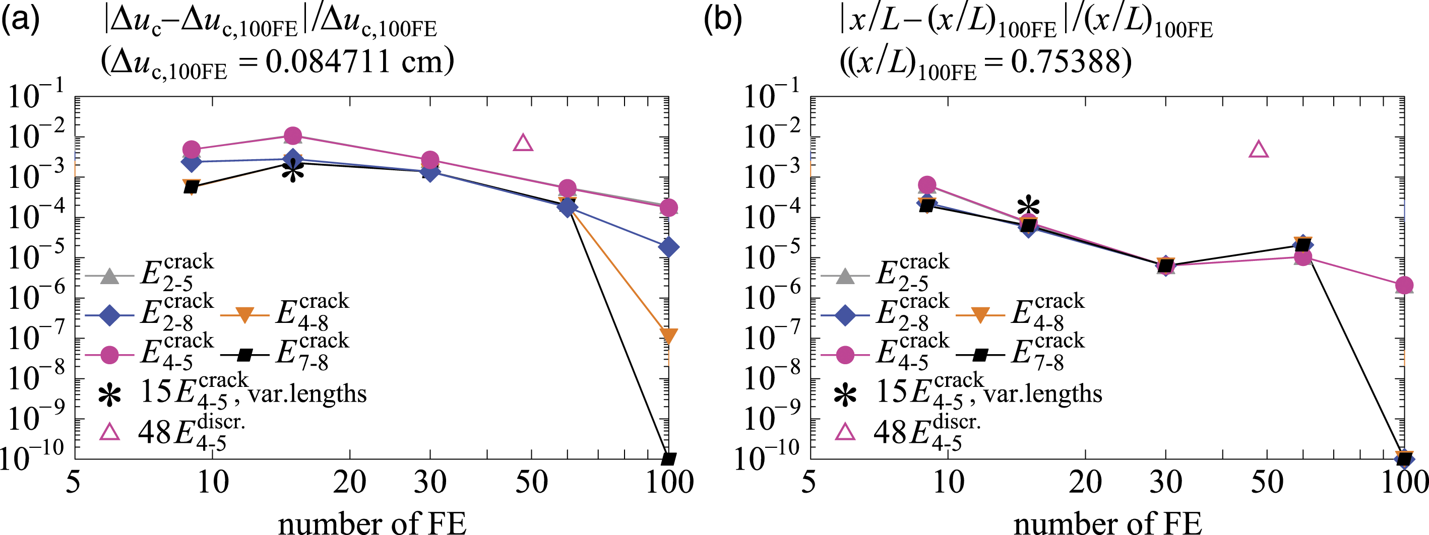
State of the bar immediately after the occurrence of the last crack r5, that is, when the stabilized state of cracks is established (see Figure 6(b)), is analysed next. As before, influence of number and type of the finite elements on elongation of concrete cover of RC bar is presented in Figure 10(a). On the other hand Figure 10(b), now depicts influence of number and type of the finite elements on the location of the crack r5. Again, the chosen reference values are numerical results obtained with 100 finite elements of type Influence of different number of finite elements on: (a) elongation of concrete part of RC bar and (b) crack width r2 at x = L/2; immediately after appearance of crack r2. Influence of different number of finite elements on: (a) elongation of concrete part of RC bar and (b) relative position of crack r5; immediately after appearance of the last crack r5.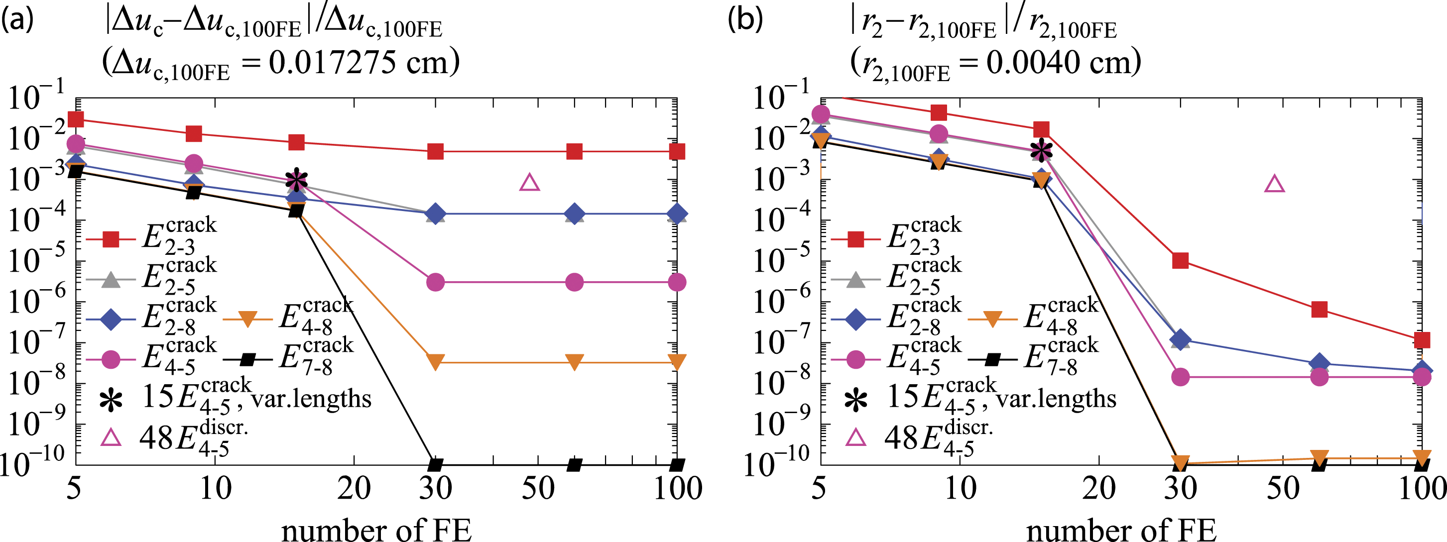
Influence of numerical integration
The second part of parametric study on accuracy of the novel family of strain finite elements is dedicated to analysis of influence of the degree and the scheme of numerical integration over the length of finite elements. As before, state of the RC bar after the appearance of the crack r2 at the notch in the middle of the bar is analysed first. Figure 11(a) depicts influence of degree of numerical integration on the elongation of the concrete cover (Δuc = L′ − L), while in Figure 11(b), its influence on the width of the crack r2 is presented. The results are shown for five different finite element meshes, namely, with 5, 9, 15, 30 and 60 finite elements of equal length, and for two integration schemes, namely, Lobatto and Gauss integration schemes, with indices L and G, respectively. Similar as in previous sections the chosen reference values are numerical results obtained with 100 finite elements of type Influence of order of numerical integration on: (a) elongation of concrete part of RC bar and (b) crack width r2 at x = L/2; immediately after appearance of crack r2.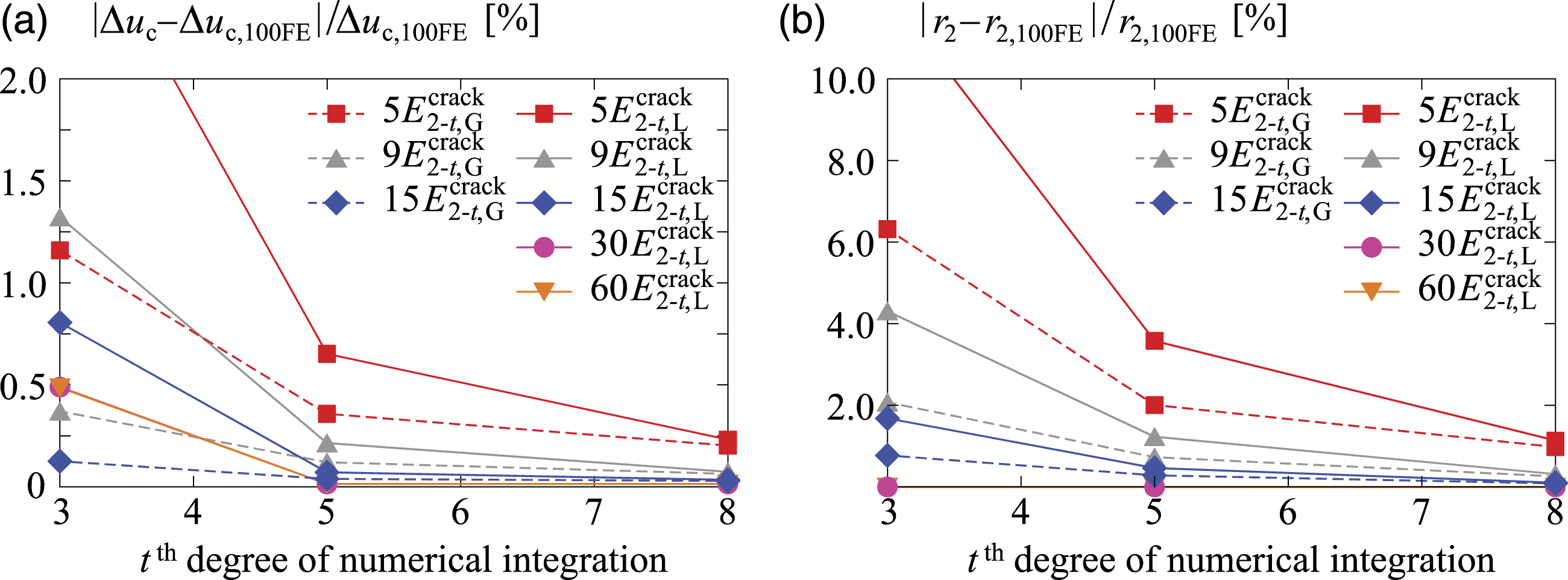
Finally, the state of the bar after the occurrence of the last crack r5 is analysed. Figure 12(a) shows influence of degree of numerical integration on the elongation of the concrete cover and Figure 12(b) depicts its influence on the location of the crack r5. Again, the chosen reference values are numerical results obtained with 100 finite elements of type Influence of order of numerical integration on: (a) elongation of concrete part of RC bar and (b) relative position of crack r5; immediately after appearance of the last crack r5.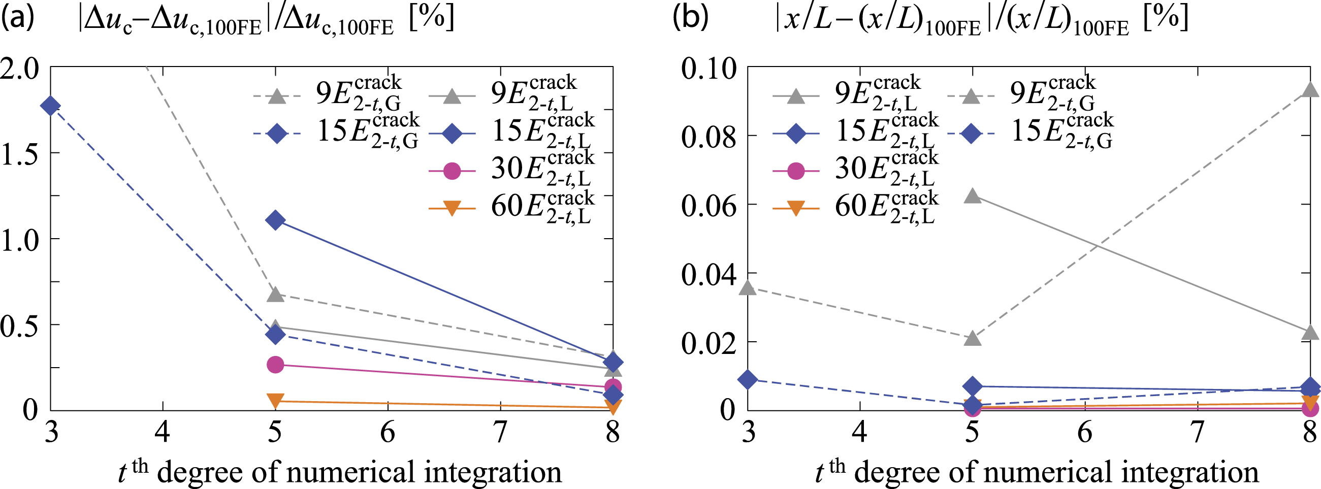
Conclusions
The paper presented a novel family of strain-based beam finite elements for analysis of tensile failure of a composite bar. The latter consists of longitudinal reinforcement surrounded by brittle concrete cover. Cracking of the cover occurs when tensile stress exceeds tensile strength of concrete. In the present model, a crack is considered as a discontinuity in a geometry of the element, while reinforcing bar bridges the crack continuously. Material softening of concrete in tension has also been considered at the crack, due to partial connection of concrete cover. The advantage of presented elements is that the crack can occur anywhere along the finite element and not necessarily at its nodes. Furthermore, the results of analysis are independent on the applied finite element mesh. In order to achieve that independence, the crack is excluded from equations of finite element and additional boundary conditions at the location of the crack are introduced. Parametric study aimed at analysis of crack occurrence and crack propagation in tensile loaded reinforced concrete bar and its results were compared to experimental results from literature. It has been shown that: 1. analysis with the lowest possible number of the novel beam finite elements 2. higher number of novel finite elements 3. in analysis with lower number of novel finite elements 4. results of analysis with finite element mesh of 15 FE with different lengths are perfectly comparable with results of analysis with same number of FE with equal lengths; the conclusion can thus be made that the use of finite element mesh with FE with different lengths for the analysis has no significant influence on the accuracy of the results.
The presented model enables efficient analysis of crack occurrence and crack propagation in RC elements with centric tensile load (such as tensile RC hangers or geotechnical anchors). As such, the model represents conceptual basis for development of the model for analysis of cracking, softening and tensile failure of brittle materials subjected to combined axial and bending load. So far, such problems in beam theory have been approached and more or less efficiently solved through the concept of plastic hinges or through the model of smeared crack (crack band element). An upgrading of the present model for possibility of occurrence of several cracks in one finite element will also be part of our future research.
Footnotes
Declaration of conflicting interests
The author(s) declared no potential conflicts of interest with respect to the research, authorship, and/or publication of this article.
Funding
The author(s) disclosed receipt of the following financial support for the research, authorship, and/or publication of this article: This work was supported by the Slovenian Research Agency [research core funding numbers P2–0158, P2–0260].