
Abstract
The corrosion resistance of the nugget zone (NZ) in two 2519-T87 aluminum alloy joints obtained by conventional friction stir welding (FSW) and tungsten inert gas arc-assisted FSW (TIG-FSW) was evaluated by immersion corrosion tests and electrochemical measurements. The results show that TIG arc significantly enhances the corrosion resistance of the nugget, the maximum corrosion depth is reduced by about 59.6%, and the polarization resistance is increased by about 14.5%. The mechanism was discussed based on microstructural examination. TIG-FSW decreases the area fraction of coarse intermetallic compounds (IMCs) with an equivalent diameter larger than 2.0 μm and increases the number of submicron IMCs, avoids the accumulation of IMCs, leads to low local electrochemical activity, and consequently enhances the corrosion resistance of the NZ.
Keywords
Introduction
2XXX (Al-Cu) aluminum alloys are widely used for the manufacture of welded structural parts such as aircraft skins, rockets, and ships due to their high-strength properties. 1 Friction stir welding (FSW) is a solid-state welding technology that is widely used in the welding of aluminum alloy structural components. Compared with traditional fusion welding, it can avoid the grain coarsening, microscopic segregation, and solidification defects and obtain a joint with high mechanical properties and corrosion resistance. 2 However, there are still some problems for FSW of aluminum alloys with high content of Cu, such as 2519 aluminum alloy. There are often many coarse Al2Cu and Al7Cu2Fe particles in this alloy. Due to the high melting point, high thermal stability, and high hardness of these intermetallic compounds (IMCs), 3 it is often difficult to significantly reduce their size and number by the heat and force generated by the conventional FSW (C-FSW). 4 As a result, micro-galvanic corrosion produced by the high concentrations of these coarse particles in the Al matrix is easy to occur and decrease the corrosion resistance of the joint. 5 Xie et al. 6 reported that the micro-galvanic corrosion of dissimilar 2219/2195 aluminum alloy friction stir welded joints is caused by the potential difference between the IMCs and the adjacent matrix and found that larger IMCs preferentially trigger pitting corrosion than smaller IMCs in corrosive solution. Kang et al. 7 also studied the effect of abnormal agglomerations of Al2Cu particles with a size of about 1–100 μm on the corrosion behaviors of the 2219-T8 friction stir welded joints, and found that Al2Cu particles are cathodic with respect to the Al matrix, leading to corrosion attack at the surrounding Al matrix. This resulted in a strong localized galvanic cell between the large cathode (abnormal Al2Cu particle aggregations) and the anode (Al matrix), triggering a more severe corrosion attack and increasing the localized corrosion density in the nearby regions. Grilli et al. 8 studied the role of IMCs in the pitting corrosion of 2219 aluminum alloy and found that Al-Cu-Fe-Mn particles act as the initiation sites of pitting; these particles are cathodic with respect to the Al matrix, and the pitting attack is concentrated at the Al matrix adjacent to the IMCs. Therefore, improving the size and distribution of IMCs can enhance the corrosion resistance of FSWed joints of aluminum alloy.
Welding parameters and stir tool can be optimized to increase material flow to break IMCs. For instance, Xu et al. 9 investigated the effect of welding parameters on the pitting corrosion of the nugget zone (NZ) in a 2219 aluminum alloy friction stir welded joint and found that pitting resistance was better with increasing traverse speed at the same rotary speed because of the finer IMCs. Kamal Babu et al. 10 investigated the effect of pin tool profiles on 2219 aluminum alloy friction stir welded joint and found that hexagonal pin profile can significantly enhance the corrosion resistance of the joint by dissolving more θ′ and θ″ precipitates and refining the grain structure. However, improving the size and distribution of IMCs through the optimization of welding parameters and stir tool structure requires extensive experimental work, and achieving a high level of reproducibility is a challenge.
Recently, a new tungsten inert gas arc-assisted FSW process (TIG-FSW) was proposed to enhance the plastic flow of materials in the 2519-T87 aluminum alloy FSWed joints by reducing the deformation resistance of the material through the high temperature of TIG arc. 11 Therefore, it may be an effective way to solve the above problems for FSW of 2519 aluminum alloys. In this work, TIG-FSW is reported to improve the size and distribution of IMCs to enhance corrosion resistance of the nugget in the 2519 aluminum alloys joint, and the mechanism has been discussed based on the effect of TIG on the features of the IMCs in the surface layer of the joint. It is of great significance because in practice both high mechanical properties and high corrosion resistance are essential for the joints.
Experimental materials and procedures
Materials and welding processes
FSW was performed using 2.5 mm 2519-T87 aluminum alloy sheets (Al-5.8Cu-0.3Mn-0.2Mg-0.2Fe-0.1Si, wt.%). During C-FSW, the rotation speed was 1600 rpm, the welding speed was 80 mm·min−1, and the stir tool was pressed to a depth of 0.3 mm with a rotation axis inclination angle of 2.5°. To soften the material and reduce the downward pressure of the stir tool, preheating the material to a temperature slightly above room temperature is recommended. 12 Meanwhile, in order to prevent coarsening of strengthening precipitates in the base metal (BM), all weldments were preheated to 75°C before welding. The welding parameters of TIG-FSW were the same as C-FSW, but the direct current electrode positive of TIG arc was applied. The shoulder diameter of the stirring tool is 10 mm; the root diameter, tip diameter, and pin length of the stir pin are 4.0, 2.8, and 2.0 mm, respectively. In TIG-FSW, TIG arc was utilized to generate high temperatures in front of the stir tool, and the TIG arc current and voltage were 8A and 20∼25 V, respectively. Additionally, the protective argon cover (with a flow of 10 L/min) was performed to shield the weldment located behind the TIG welding gun, without any interference with the stability of TIG arc. The detailed TIG-FSW process can be found in Ref. 11 The weldments were cooled to room temperature in the air. To investigate the effect of TIG arc on the features of IMCs, the cross-sectional microstructure of the treated samples was examined.
Microstructural characterization
Specimens were ground and mechanically polished and examined using a Leica DM2700 M optical microscope (OM) and a Zeiss MA 10 scanning electron microscope (SEM) with an energy-dispersive X-ray spectroscopy (EDS). The size and area fraction of IMCs were estimated by Image J software. 13 Foils approximately 0.1 mm in thickness were cut from the region situated approximately 0.2 mm below the joint surface in the NZ. Subsequently, these foils were thinned and punched into circular disks with a diameter of 3 mm and underwent twin-jet polishing in a solution consisting of 30% HNO3 and 70% CH3OH (Vol.) at about −20°C. The precipitates in the NZ of the two joints were examined using a Talos F200X G2 scanning transmission electron microscope (STEM) equipped with a high-angle annular dark field (HAADF) detector operated at 200 kV.
Immersion tests
The corrosion immersion test was performed according to ASTM G34-2001 specification. The specimen size was 50 mm × 20 mm × 2.5 mm. The joint surface was tested and the other five surfaces were sealed. Before test, the specimens were ground and polished to remove the groove-like structure on the surface of the NZ. The specimen was immersed in a solution of 234 g NaCl + 50 g KNO3 + 6.3 ml HNO3 diluted to 1L by deionized water for 96 h. The pH value of the solution was about 0.4. The ratio of the solution volume to the test area of the specimen was 20 ml/cm2. The test temperature was controlled at 25 ± 3°C in a water bath.
In order to better understand the corrosion behavior on the surface of the NZ in the two joints, some specimens were immersed in the solution for different time, taken out, and then cleaned with water and finally dried in air. Subsequently, they were examined by SEM and EDS.
Electrochemical tests
The standard three-electrode system was adopted for the electrochemical test and the test instrument was Metrohm Multi AUTOLAB M204. The working electrode was the surface of the NZ with an area of 1 cm2. The specimen was prepared by the same method as that for the immersion test. The reference electrode was a saturated calomel electrode, and the auxiliary electrode was a platinum electrode. All electrochemical tests were carried out in 3.5 wt.% NaCl solution at room temperature. The open-circuit potential measurement was first performed to ensure that the system was in equilibrium; the frequency range of electrochemical impedance spectroscopy (EIS) measurement was 0.01 Hz to 100 kHz and the excitation voltage was ±10 mV. The test data were fitted by Zsimpwin software.
Results and analysis
Microstructure
Figure 1 shows SEM images of the IMCs in the surface layer of the cross-section of the joints. In the BM (Figure 1(a, a1)), the average composition of the spherical IMCs was 68.0 ± 7.1 at.% Al and 32.0 ± 3.4 at.% Cu, which is presumed to be Al2Cu particles. 14 The equivalent diameter of Al2Cu particles is from about 1.0 to 9.0 μm and the equivalent diameter is the equivalent circle diameter converted from the area. The average composition of the blocky IMCs was 60.6 ± 5.7 at.% Al, 6.4 ± 1.2 at.% Fe and 33.0 ± 2.4 at.% Cu, which is presumed to be Al7Cu2Fe particles. 15 The length and width of Al7Cu2Fe particles are about 1.0∼13.0 μm and 0.5∼1.5 μm, respectively.
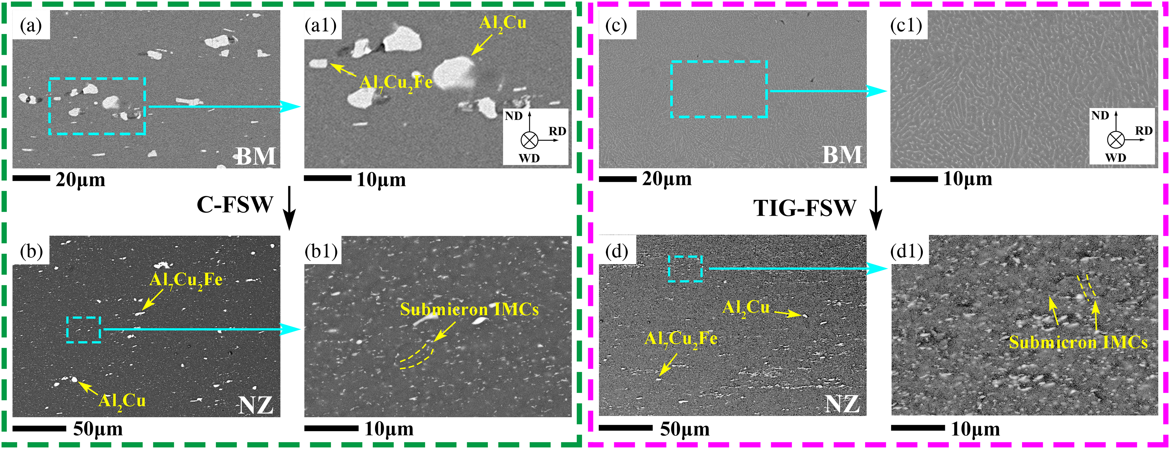
SEM images of the IMCs in the weldment surface layer of the cross-section of the different zone. (a), (a1) and (c), (c1) are the BM without TIG arc treatment and solidified material with TIG arc treatment, respectively; (b), (b1) and (d), (d1) are the NZ in the C-FSW and TIG-FSW joints, respectively. ND and RD are the normal direction and rolling direction of the sheet, respectively. WD is the welding direction.
In the C-FSW joint, a large number of spherical and blocky IMCs with smaller sizes can be observed in the NZ, see Figure 1(b), and the area fraction is about 1.34 ± 0.04%. The size distribution of these IMCs is shown in Figure 2. Their equivalent diameters are mainly in the range of 1.0∼2.7 μm with a frequency of about 85.3%. The largest equivalent diameter of IMCs is about 5.5 μm. In addition, submicron IMCs can be observed at grain boundaries, see Figure 1(b1), and their area fraction is about 2.03 ± 0.04%.
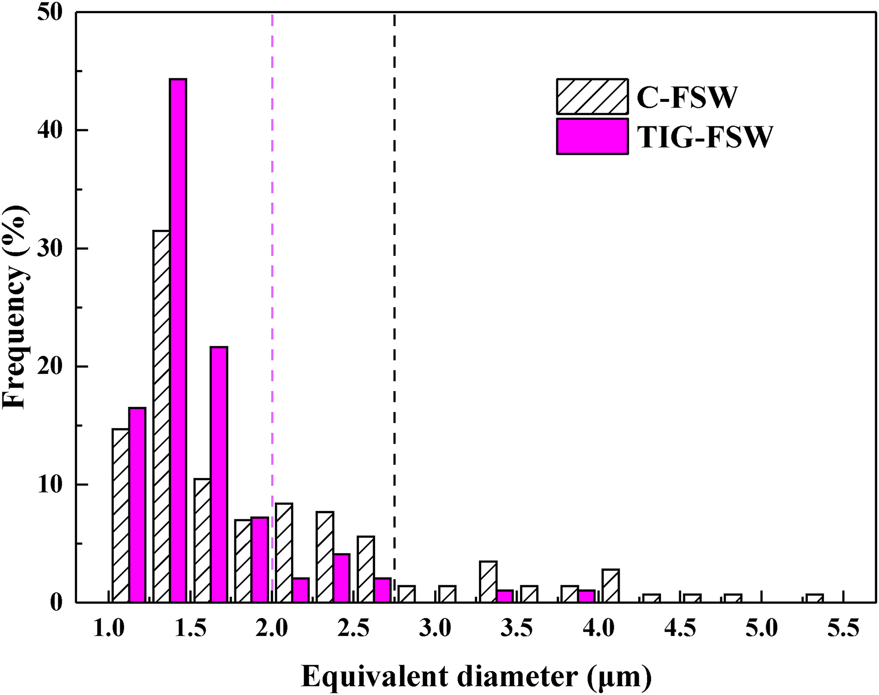
Size distribution of IMCs in the NZ of the two joints.
SEM images of the surface layer of BM treated by TIG arc are shown in Figure 1(c, c1). There are no coarse IMCs but fine unconnected eutectic networks. After further FSW, IMCs in the surface layer become finer and denser, see Figure 1(d), and the area fraction is about 0.80 ± 0.08%, which is smaller than that of C-FSW joint. The equivalent diameter of IMCs in the surface layer is mainly in the range of 1.0∼2.0 μm with a frequency of 89.7%, see Figure 2, and the largest equivalent diameter of IMCs is about 4.0 μm, which is smaller than that of C-FSW joint. A larger number of submicron IMCs can be observed at grain boundaries and in the interior of grains, see Figure 1(d1), with an area fraction of about 4.29 ± 0.07%. Moreover, from Figure 2, the frequency of coarse IMCs with equivalent diameter larger than 2.0 μm is about 36.4% in the NZ of the C-FSW joint, obviously higher than that of 10.3% in the NZ of the TIG-FSW joint, and the area fraction is about 1.01 ± 0.01% and 0.28 ± 0.01%, respectively. As a result, in the NZ surface layer of the TIG-FSW joint, the reduction rate of the area fraction of coarse IMCs is about 72.0%, while the increased rate of submicron IMCs area fraction is about 111.3%. There is a homogeneous distribution of the small IMCs in the NZ of the TIG-FSW joint, and it is difficult to see the cumulation of coarse IMCs as that in the C-FSW joint.
2519 aluminum alloy is a heat-treatable alloy, and high strength comes from the presence of disk-shaped θ′ precipitates. Figure 3 gives typical HAADF-STEM images and selected area electron diffraction (SAED) patterns, captured with the electron beam near the <001 > Al direction, to reveal the features of intragranular and grain boundary precipitates in the NZ of the two joints.
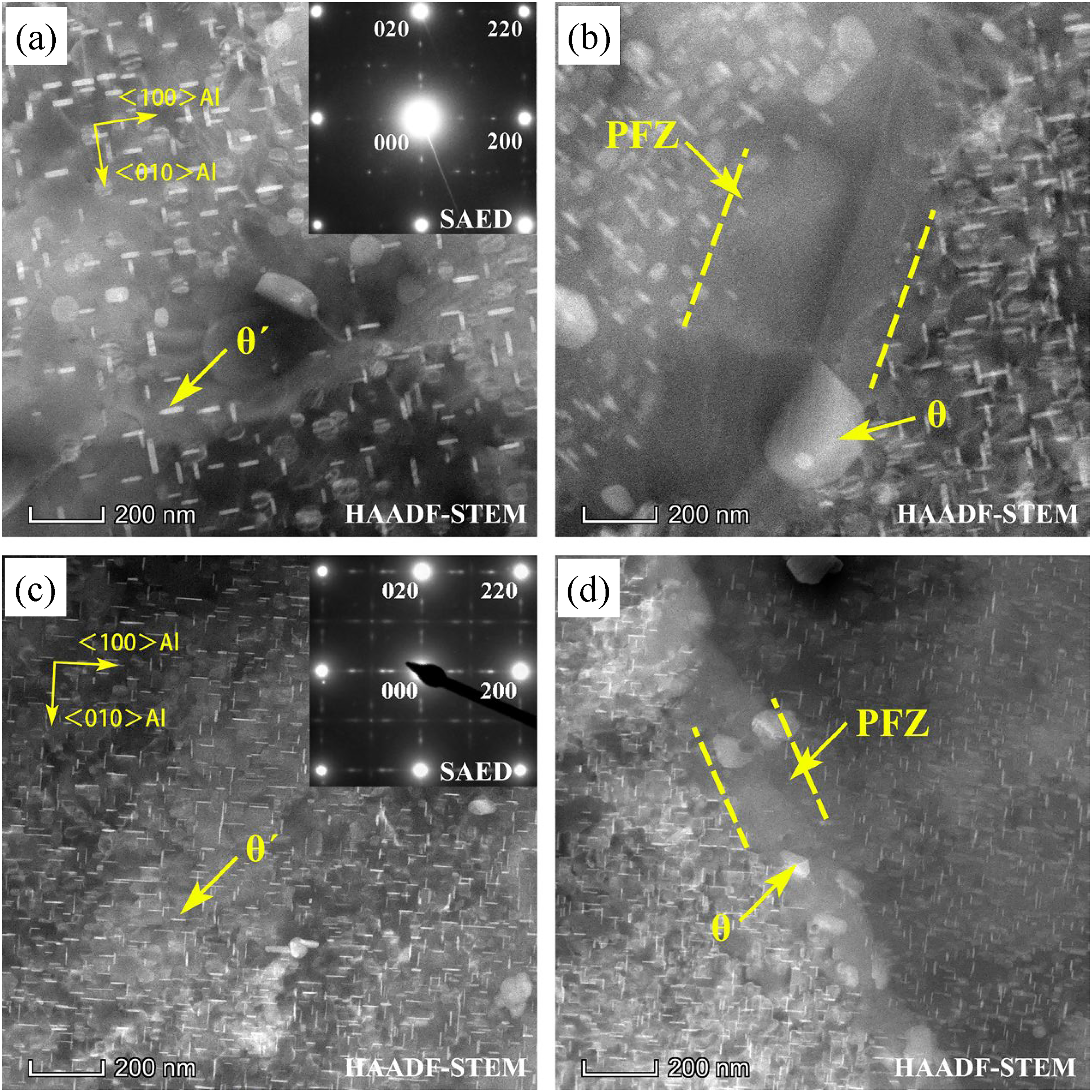
HAADF-STEM images and the corresponding SAED patterns of intragranular and grain boundary precipitates in the NZ of the (a, b) C-FSW and (c, d) TIG-FSW joints. The electron beam is close to <001>Al direction.
In the NZ of the C-FSW joint, there is a uniform distribution of intragranular precipitates with the diameter of 51.0 ± 10.3 nm, the thickness of 10.5 ± 2.7 nm, and the number density of 58 ± 13 μm−2 (Figure 3(a)). Based on the SAED pattern, the distinct diffraction spots at approximately 1/2{200}Al and 1/2{220}Al indicate that the intragranular precipitates are θ′ precipitates. 16 The grain boundary precipitates are the significantly coarsened θ precipitates 17 with the equivalent circle diameter of 203 ± 50.2 nm and exhibit discontinuous distribution with the spacings of 524 ± 83.4 nm. Moreover, there is a large precipitate free zone (PFZ) close to grain boundary with the width of 537.4 ± 22.5 nm, see Figure 3(b).
While in the TIG-FSW joint, finer θ′ precipitates with a higher density are present in the Al matrix of the NZ (Figure 3(c)), and their diameter, thickness and number density are 35.5 ± 9.1 nm, 4.6 ± 1.5 nm and 471 ± 35 μm−2, respectively. θ precipitates at grain boundary did not experience severe coarsening and exhibit smaller spacings, and narrower PFZ near grain boundary can be seen, from Figure 3(d); the diameter and spacing of θ precipitates are 84.2 ± 19.2 nm and 181.3 ± 96.9 nm, respectively, and the width of PFZ is 198.6 ± 30.4 nm.
Corrosion features
In the Al-Cu alloys friction stir welded joints, the corrosion resistance of the NZ is higher than that of the TMAZ, HAZ, and BM. 18 The corrosion behavior of these zones was found to differ from one to another. This work focused on the corrosion behavior of the NZ. Figure 4 shows the corrosion features of the NZ cross-section of the two joints immersed in the corrosive solution for 96 h. In the C-FSW joint, the NZ is mainly dominated by pitting corrosion and intergranular corrosion, see Figure 4(a–a3), and the ratio of the corroded zone (corroded length to NZ length) is 41.7%. The corrosion pits are large and oval in shape and the maximum corrosion depth is about 183 μm. There is obvious intergranular corrosion at the bottom of the corrosion pit. It is worth noting that there are submicron IMCs and coarse IMCs near the corroded grain boundaries, as shown by arrows in Figure 4(a3).
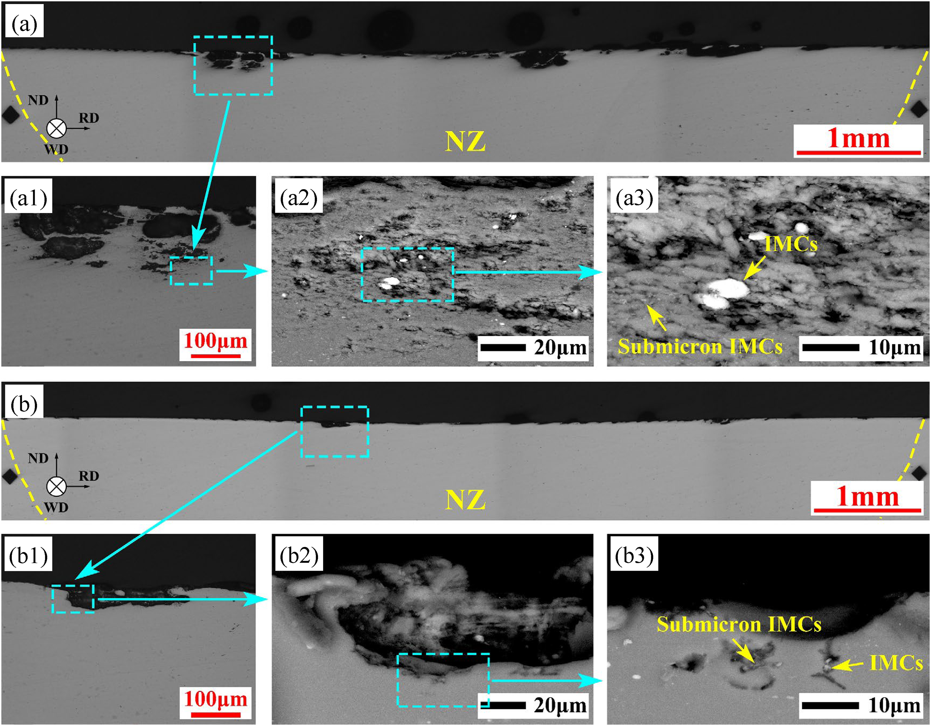
Corrosion features of the cross-section of the NZ in the (a–a3) C-FSW and (b–b3) TIG-FSW joints. (a), (a1), (b), and (b1) are OM images. (a2), (a3), (b2), and (b3) are SEM images.
While in the TIG-FSW joint, mainly pitting corrosion is visible in the NZ, see Figure 4(b–b3), and the ratio of the corroded zone is 15.5%. The corrosion pits are flat and the maximum corrosion depth is about 74 μm. No obvious intergranular corrosion can be found at the bottom of the corrosion pit. Moreover, few coarse IMCs are observed around the corrosion pit. In conclusion, the maximum corrosion depth and the ratio of the corroded zone in the NZ of the TIG-FSW joint are smaller than those in the C-FSW joint.
Figures 5 and 6 present SEM images showing the morphology of the same region in the NZ of the two joints before and after immersion. It can be seen from Figure 5(a) that the NZ of the C-FSW joint contains a large number of coarse IMCs including Al2Cu and Al7Cu2Fe particles. Based on the EDS mapping in Figure 5(a1), the position of Al2Cu and Al7Cu2Fe particles are indicated by blue and purple arrows, respectively. After immersion for 6 h, dissolution of the Al matrix surrounding Al7Cu2Fe particles occurred, leading to pitting corrosion, as indicated by yellow arrows in Figure 5(b), and the diameter and number density of these pits are about 1∼5 μm and 6.62 × 103 mm−2, respectively. Some cracks can be seen between Al7Cu2Fe particles and their adjacent Al matrix, see the yellow dotted frame in Figure 5(b). However, it is difficult to see the same phenomenon for Al2Cu particles, see Figure 5(a) and (b). When the immersion time was prolonged to 12 h, the number density of pits increased rapidly to about 12.57 × 103 mm−2, and some pits evolved into intergranular corrosion, see Figure 5(c).
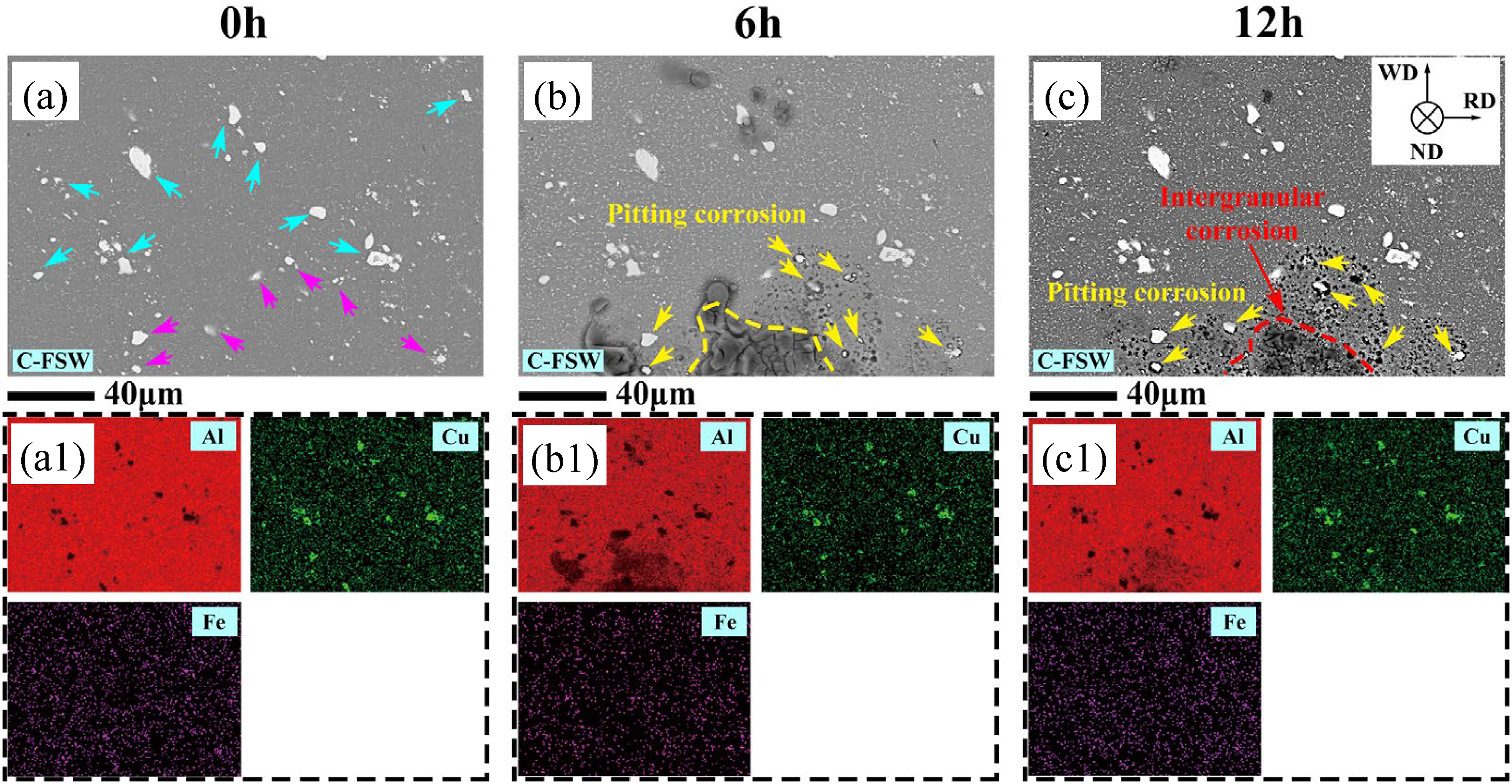
Corrosion morphology on the surface of the NZ in the C-FSW joint after immersion. (a), (b), and (c) are SEM images of the zone immersed for different times; (a1), (b1), and (c1) are the EDS mapping of various elements.
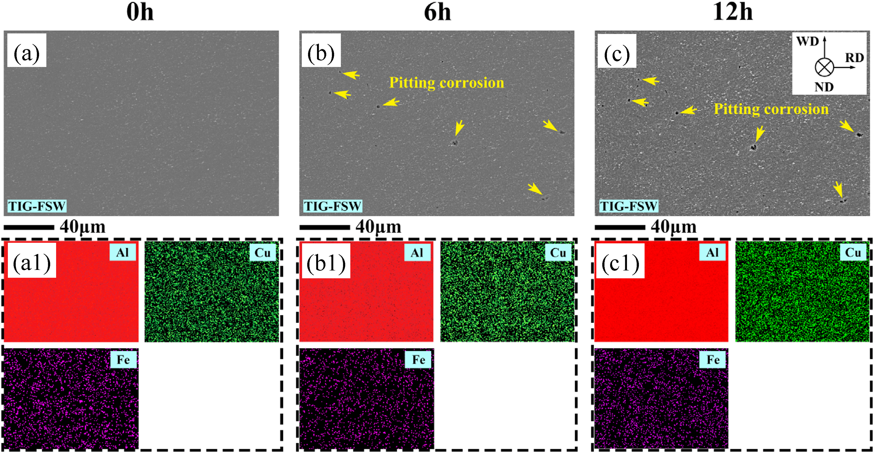
Corrosion morphology on the surface of the NZ in the TIG-FSW joint after immersion. (a), (b), and (c) are SEM images of the zone immersed for different time; (a1), (b1), and (c1) are the EDS mapping of various elements.
While in the TIG-FSW joint, a higher density of finer IMCs can be observed in the NZ (Figure 6(a)), but their position cannot be identified via the EDS mapping. However, these particles are believed to be Al2Cu and Al7Cu2Fe particles. After immersion for 6 h, there is slight pitting corrosion in the NZ, as indicated by yellow arrows in Figure 6(b), and the diameter and number density of these pits are about 1∼3 μm and 0.18 × 103 mm−2, respectively. As the time prolonged to 12 h, the pits exhibited a slight increase in size and number, but did not evolve into intergranular corrosion, as shown in Figure 6(b) and (c). In conclusion, the susceptibility to pitting and intergranular corrosion is higher in the NZ of the C-FSW joint than in the TIG-FSW joint.
Electrochemical impedance spectroscopy
Figure 7 shows the Nyquist plot and equivalent circuit of the NZ in the two joints. Rs is a solution resistance; CPEr is the oxide film capacitance, Rr is the oxide film resistance, CPEdl is the electric double-layer capacitor, Rct is the charge transfer resistance and RP is a polarized resistance (RP = Rr + Rct). A higher value of RP often indicates higher corrosion resistance of the alloy. 19 Moreover, a lower CPEr/CEPdl ratio indicates a lower degree of localized corrosion. 20
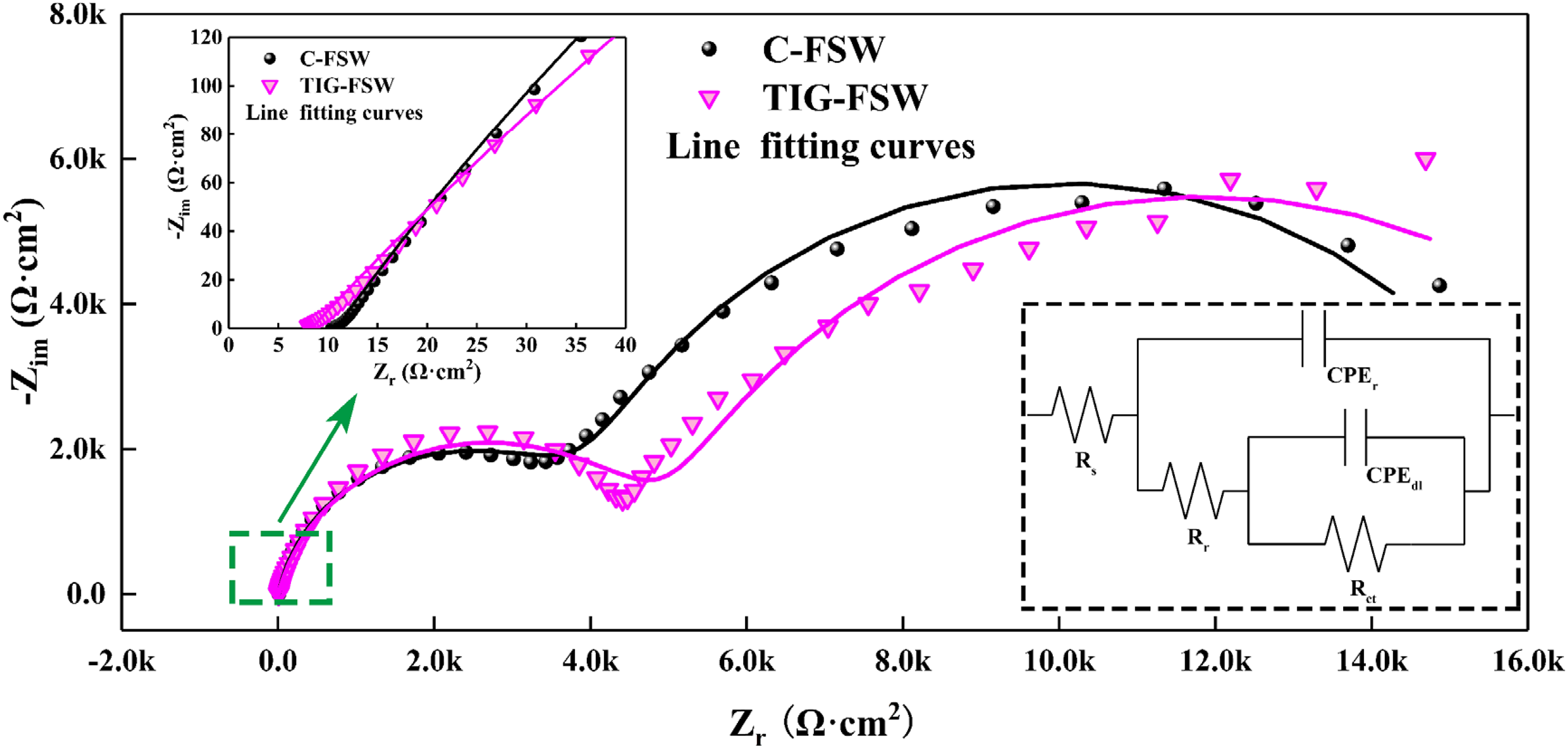
Nyquist plot of electrochemical impedance spectroscopy of the NZ in 3.5wt% NaCl solution.
After the introduction of TIG arc, the Rp of the NZ is increased from 1.66 × 10⁴Ω·cm2 to 1.90 × 10⁴Ω·cm2 with an increased rate of 14.5%; meanwhile, the CPEr/CEPdl ratio of the NZ is reduced from 7.7% to 3.0% with a decreased rate of 61.0%. These results indicate the NZ in the TIG-FSW joint has better corrosion resistance, which is in good accordance with the immersion results shown in the previous section.
Discussion
Based on the above results, it is known that the introduction of TIG arc can effectively break down the coarse IMCs in the joints. During C-FSW, due to mechanical stirring and welding thermal cycles, most coarse IMCs were broken into smaller ones (Figure 1(a) and (b)), but there are still some coarse IMCs survived in the NZ. While during TIG arc treatment, the IMCs in the surface layer of the BM can be melted into the molten pool by the TIG arc with a peak temperature about 3500 K. 21 Fine discontinuous eutectic particles formed and exhibited an unconnected eutectic network during the short cooling period, see Figure 1(c) and (c1). As a result, the number of coarse IMCs in the surface layer (Figure 1(c)) is drastically reduced. Then, the heat and force generated by the further FSW promote the dissolution of these particles into the Al matrix, resulting in a high concentration of solutes in the solid solution. During subsequent cooling, many new submicron IMCs formed at grain boundaries and in the interior of grains, resulting in the precipitation features observed in Figure 1(d1). Consequently, IMCs have higher number density, smaller sizes and distribute more homogeneously in the NZ of the TIG-FSW joint than the C-FSW one, and this can avoid the cumulation of coarse IMCs and enhance the corrosion resistance of the NZ as described schematically in Figure 8.
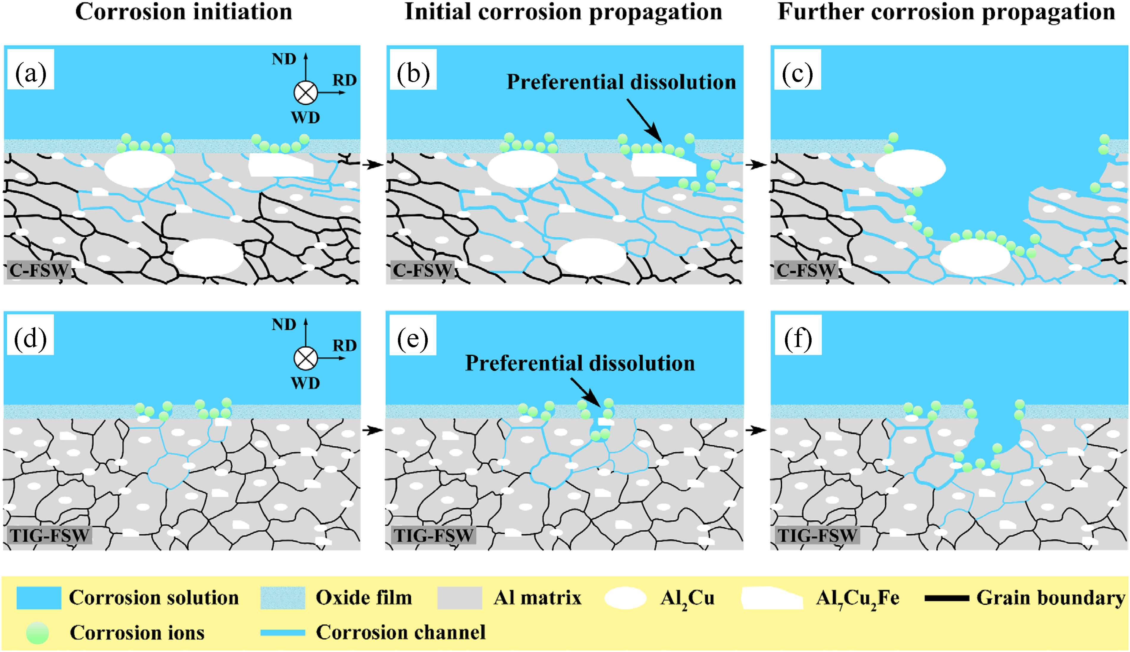
Schematic of corrosion processes on the cross-section in the NZ of the (a–c) C-FSW and (d–f) TIG-FSW joints.
In the C-FSW joint, the coarse IMCs in the NZ surface layer contribute to the formation of oxide film defects, and the corrosive ions (such as Cl−) in the solution preferentially nucleate at the oxide film defects, 22 which accelerates the rupture of the oxide film, as described schematically in Figure 8(a). When the oxide film is broken, Al7Cu2Fe particles act as a cathode and induce the preferential dissolution of the Al matrix in their vicinity; 23 meanwhile, corrosion products accumulate at the pits and form occluded cells, and therefore Fe is dissolved from Al7Cu2Fe particles and Al7Cu2Fe particles are dealloyed, which promotes the occurrence of pitting corrosion, 24 see Figure 5(a) and (b). Moreover, when Al2Cu and Al7Cu2Fe particles are immersed in the solution, Al2Cu particles act as cathode, and Al7Cu2Fe particles act as an anode, which accelerates the dealloying of more Al7Cu2Fe particles and promotes pitting corrosion, 25 as described schematically in Figure 8(a) and (b). Then, with the dissolution of the Al matrix, the physical separation of Al7Cu2Fe particles from the Al matrix results in the formation of pits (Figure 4(a) and (a1)). Meanwhile, the large PFZ of grain boundary (Figure 3(b)) promotes the propagation of intergranular corrosion to the interior of the NZ (Figure 4(a2) and (a3)), as described schematically in Figure 8(c). In addition, the high concentration of cations on the surface of the NZ resulting from the attack in the area of high concentration of Al7Cu2Fe particles leads to high local electrochemical activity, promoting corrosion propagation. This consequently exposes new areas to the corrosive environment, and contributes to the corrosion propagation in a large range, see Figure 5(a-c).
While in the TIG-FSW joint, a more dispersed distribution of finer IMCs in the NZ surface layer (Figure 1(d) and (d1)) contributes to the formation of uniform oxide film, and therefore effectively hinder the nucleation of aggressive ions, as described schematically in Figure 8(d). When the oxide film is broken, the smaller IMCs (Figure 1(d)) can reduce the anodic dissolution of the surrounding matrix, 26 causing a less severe attack in the surrounding matrix than that around the larger IMCs (Figure 6(b)), as described schematically in Figure 8(d). Moreover, a more dispersed distribution of finer Al2Cu and Al7Cu2Fe particles weakens the galvanic corrosion, which hinders pitting corrosion, as described schematically in Figure 8(d) and (e). Then, as the corrosion reaction proceeds, the weakened anodic dissolution of the matrix leads to the less physical separation of IMCs from the matrix, and therefore the number of pits is reduced (Figure 4(b) and (b1)). Meanwhile, the narrower PFZ of grain boundary (Figure 3(d)) hinders the propagation of intergranular corrosion to the interior of the NZ, 27 as described schematically in Figure 8(f). In addition, on the surface of the NZ, the homogeneous distribution of the small particles leads to low local electrochemical activity, preventing corrosion propagation in a large range, see Figure 6(a–c). As a result, the corrosion resistance is enhanced.
Conclusions
After the introduction of TIG arc, the maximum corrosion depth, the ratio of the corroded zone, and the CPEr/CEPdl ratio in the NZ are reduced by about 59.6%, 62.8%, and 7.7% respectively; meanwhile, the Rp of the NZ is increased by about 14.5%. These results indicate that the NZ has better corrosion resistance in the TIG-FSW joint than the C-FSW joint of 2519 aluminum alloy.
TIG-FSW can reduce the area fraction of coarse IMCs with an equivalent diameter larger than 2.0 μm by about 72.0%, and increase the area fraction of submicron IMCs by about 111.3%. Therefore, the homogeneous distribution of the small particles leads to low local electrochemical activity, which contributes to higher corrosion resistance of the NZ.
In the NZ of the FSW joint, Al7Cu2Fe particles are prone to the initiation of pitting corrosion, while Al2Cu particles accelerate the dealloying of Al7Cu2Fe particles, and therefore promote corrosion. Reducing the number of IMCs with an equivalent diameter larger than 2.0 μm may effectively reduce the local electrochemical activity and therefore enhance corrosion resistance.
Footnotes
Acknowledgements
The authors are grateful to the personnel of the National Engineering Research Center of Near-net-shape Forming for Metallic Materials at South China University of Technology and Prof. Datong Zhang for experimental assistance.
Declaration of conflicting interests
The authors declared no potential conflicts of interest with respect to the research, authorship, and/or publication of this article.
Funding
The authors received no financial support for the research, authorship, and/or publication of this article.