
Abstract
Mass timber panels are increasingly used in mass timber and hybrid construction projects for efficient off-site construction. Conventional continuous floating concrete toppings often struggle to achieve an apparent impact insulation class (AIIC) above 55 when tested according to ASTM standards. This study explores the impact sound insulation of raised discrete floating floor assemblies on cross-laminated timber (CLT) and dowel-laminated timber (DLT) floors through experimental testing. The study found that a raised discrete floating floor, constructed using commercially available dry materials such as oriented strand board (OSB), cement board, and gypsum board, significantly improved impact sound isolation and reduced the need for thick concrete layers. Interestingly, increasing the thickness of the floating concrete topping from 38 to 100 mm had minimal effect on sound insulation. Instead, cement boards provided an effective alternative, achieving an AIIC rating of 65 and offering a dry solution for improving sound insulation in timber construction.
Keywords
Introduction
The recent development of mass timber panels (MTPs) and related construction techniques in North America creates opportunities to erect tall wood buildings. MTP is a category of panalized engineered wood products of large dimensions, including cross-laminated timber (CLT), dowel-laminated timber (DLT), glued-laminated timber (GLT), structural composite lumber (SCL) and their hybrid versions. 1 In addition to the widely used CLT, DLT panels are also being subjected to vibration and acoustic tests. DLT is made of wood lamellas and connected with hardwood dowels instead of glue, a more environmentally friendly alternative to CLT. 2 Both CLT and DLT have the advantages of lightweight prefabrication availability 3 and are applicable for rapid dry off-site construction techniques. 4 Their low mass and stiffness make them susceptible to acoustic excitation, presenting challenges for achieving adequate sound insulation. 5 Consequently, their acoustic performance often falls short of adequate occupant comfort. 6 It was reported that bare CLT panels cannot achieve satisfactory sound insulation and ensure occupant comfort, making supplementary solutions essential.7–9 Moreover, low-frequency impact sound should be further enhanced to meet sound insulation expectations, which concludes lower frequency than 100 Hz.10,11
Improving the impact sound insulation performance in mass timber buildings has become an important area of focus in recent years. Continuous floating concrete and raised floor systems are two common approaches for improving impact sound insulation.12–17 The continuous floating concrete floor solutions are adopted for mass timber floors, which have been tested at different laboratories and are being used in mass timber buildings.18–21 They have demonstrated high insulation efficiency in reducing mid- to high-frequency impact noise.12,22 For CLT floors, a lab test with floor mounts from AMC Mecanocaucho, 23 based on ISO 10140-3, 24 demonstrated that isolation techniques significantly improved impact insulation, highlighting its potential for mitigating flanking sound transmission. The report 25 from National Research Council Canada provided the impact sound insulation test resusults of a 175-mm CLT floor with various assemblies. Floating a 38-mm concrete topping on a 10-mm tar board improved the AIIC rating from 26 to 36. As the concrete topping is typically cast in place on the mass timber structural floor, adding to the structure’s dead load and requiring curing time. The floating concrete topping with a continuous elastic interlayer was unable to reach an AIIC rating above 55. 26
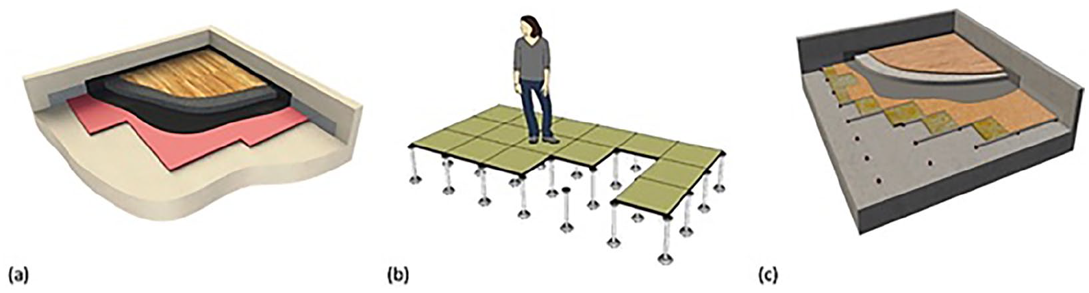
In addition to the acoustic considerations, casting concrete toppings requires additional curing time. These drawbacks limit the advantages of rapid construction offered by MTPs in tall wood buildings, creating a need for high-performance, concrete-free dry floating floor solutions. According to FPInnovations 27 , they designed and tested a raised floor on mass timber slabs with an AIIC rating higher than 55, demonstrating strong potential for further enhancements that could achieve ratings above 60. Another new concept of raised floors with sound insulation components was designed and tested for insulating low-frequency impact noise. 28 This raised floor was modified based on the conventional raised floor (also known as access flooring) by installing rubber mounts at the bottom of the supports to create an additional vibration isolation layer. In comparison, conventional raised floor systems consist of a support structure and upper panel without rubber mounts. Their primary purpose is to provide a flat surface and create space for mechanical and electrical services. In contrast, the recently developed raised discrete floating floor system introduces discrete rubber floor blocks that serve both as mounts and support structures. Unlike traditional systems that use rubber, plastic, or metal mounts primarily for surface elevation and utility concealment, the innovative system specifically integrates vibration isolation mounts for improved vibration and sound insulation between the mass timber structural floor and the upper flooring. While traditional systems prioritize utility space, the discrete system focuses on enhancing acoustic comfort and addressing structural concerns. Additionally, surface finishes can be directly applied to the rubber mounts, and mass toppings can be added to the raised floors, transforming them into an advanced discrete raised floating floor assembly. The difference between types of floors is presented in Figure 1. The recent research on the raised discrete floating floor showed that the block mounts had high vibration isolation performance in the middle to the high frequency on the light wood joist structural floor. 29 Compared with the continuous floating floor system, its acoustic performance was not fully explored, especially on mass timber floors. Furthermore, the assembly of a discrete floating floor might create an enclosed space between the structural and finishing floor, which should also fulfill the fire code considerations for concealed space. 30 Therefore, more research is needed to develop high-performance raised discrete floating floor solutions for mass timber buildings that consider both sound insulation and fire requirements.
In this study, the impact sound insulation performance of the discrete floating floor was tested on CLT and DLT mass timber floors through a mock-up room approach. Three types of discrete floor block mounts were used as point bearings of the raised discrete floating floor, and multiple dry mass topping materials were floated besides pre-cast concrete toppings. Furthermore, impact sound tests were conducted on full-size (5.0 m × 3.6 m) discrete raised floating floor assemblies to compare with test results of small-size assemblies. The impact sound insulation performance of the discrete raised floating floor was compared to that of selected continuous floating concrete assemblies. The apparent normalized impact sound pressure level (ANISPL) spectra according to ASTM E1007-16
34
were measured and discussed. The single number quantities (SNQs), including AIIC single number rating according to ASTM E989-06
33
and
Material and methods
Materials
CLT and DLT panels were selected as the structural floors for mounting acoustic floor blocks and conducting impact sound tests. The tested CLT floor was made of three pieces of 4.0 m × 1.8 m × 0.139 m spruce-pine-fir (SPF) CLT panels (CrossLam CLT 139 V). The panels were spanned in the major strength direction on the mock-up room at 3.8 m on center. The tested floor was made of 2 pieces of DLT panels (StructureCraft, BC, Canada) of dimensions 5.4 m × 4.0 m × 0.140 m, made of spruce-pine-fir (SPF), and covered by 11 mm OSB sheathing panels. The panels were spanned in the major strength direction at 5.2 m on center. Panel-to-panel and panel-to-wall connections were achieved with ϕ8.5 mm × 215 mm fully-thread self-tapping screws with the spacing of 40 cm. All gaps between the floor to wall were sealed with acoustic sealant and tapes.
Discrete floor block mounts, supplied by Getzner (Getzner Werkstoffe GmbH, Austria) and AMC Mecanocaucho (AMC Mecanocaucho, Spain), were used to isolate the floor structure. Getzner named the elastomer floor block material as Sylomer, plus a numeric suffix to indicate the maximum allowable load per mount. It is worth mentioning that AMC Mecanocaucho developed its innovative metal frame as an AMC-patterned floor block mount using Getzner Sylomer blocks. In this study, Sylomer60 (AFB) from Getzner, AMC25 and AMC40 from AMC Mecanocaucho were used as floor block mounts in the raised discrete floating floor assemblies. The AFB had a great capacity of 60 kg load per mount, while AMC25 and AMC40 had a designed capacity of 25 and 40 kg per mount, respectively. The discrete floating floor system was assembled using various elastomeric point-bearing blocks to support the mass toppings, as illustrated in Figure 2. AFB blocks were adhered to the structural floor with 60 cm spacing. Wood sleepers, measuring 19 mm × 64 mm, were then affixed on top of the AFB blocks using polyurethane adhesive. 11 -mm-thick OSB panels were fastened together with a wood sleeper by 38 mm long wood screws, and the remaining cavity was filled with 89 mm mineral wool (Rockwool) insulation. AMC floor block series consisted of a 50 mm × 50 mm × 25 mm elastomer blocks, and a metal mounting frame. AMC floor mounts were secured to the structural floor using 32 mm screws, with a spacing of 50 cm between each mount point. Then, the 50 mm × 50 mm wood sleepers were placed and fixed on the mounts, and 89 mm mineral wool insulation filled the cavity. Finally, an 11 mm OSB panel was placed on the top of the wood sleepers and fastened by 38 mm in length wood screws.
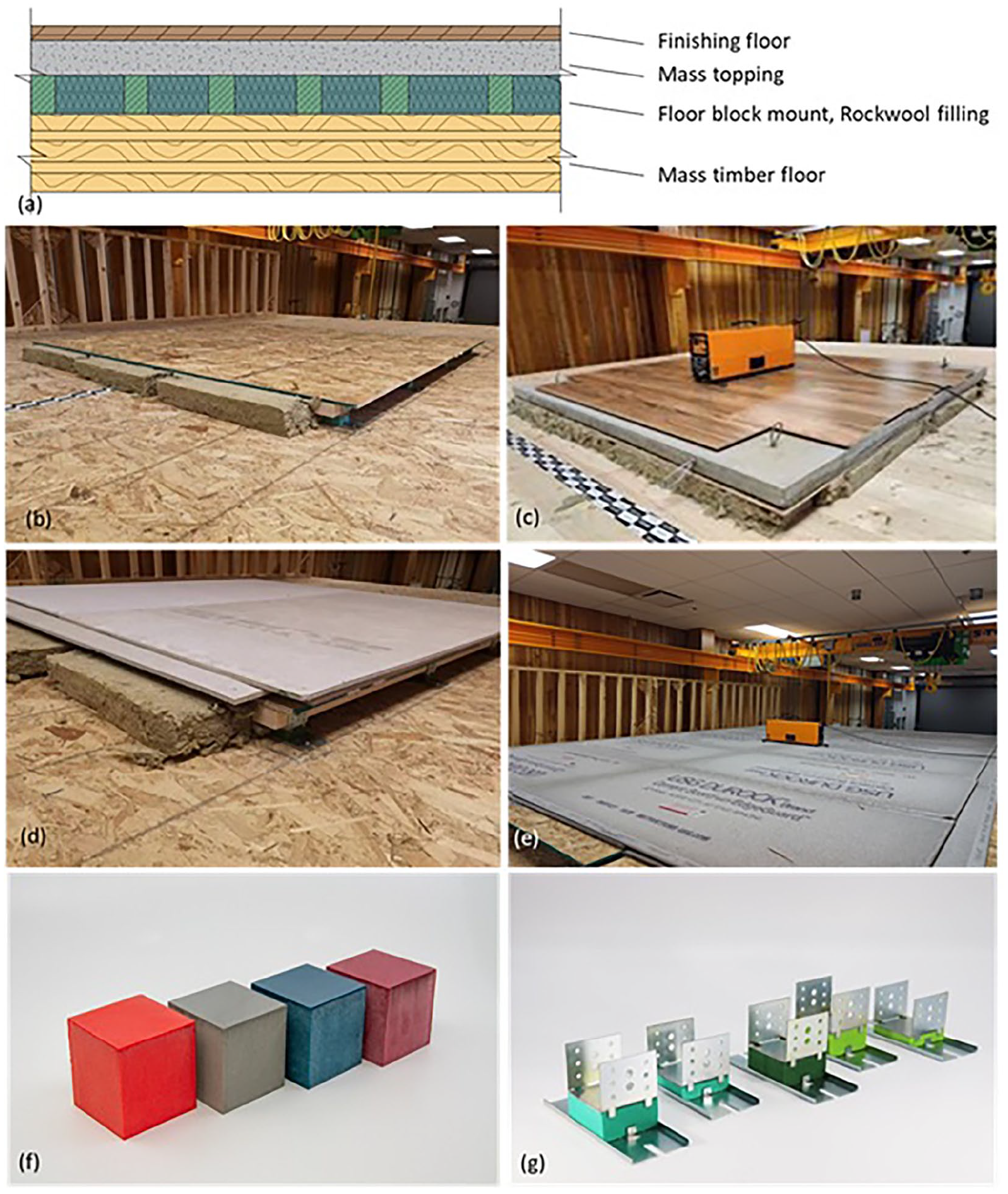
The schematic diagram for: (a) discrete floating floor system, (b) raised discrete floor without mass topping, (c) floating concrete topping, (d) floating triple layer HardieBacker cement boards, (e) full-size setup floating double layer USG cement boards, (f) AFB floor mounts, and (g) AMC25 and AMC40 floor mounts.
Four pre-cast 1.6 m × 1.6 m normal strength (35 MPa) concrete toppings (38, 50, 70, and 100 mm) were floated as mass toppings. The concrete masses were 234, 307, 430, and 614 kg, equivalent to an area density of 91, 120, 168, and 240 kg/m2, respectively. Besides the pre-cast concrete toppings, two types of cement boards and one type of gypsum board were selected as the dry solution for the floating floor. Gypsum board is the most commonly used drywall material in residential construction, and it demonstrates fire-resistance properties to enhance the fire resistance level of a discrete floating floor. Each floated layer of 11 mm cement board (HardieBacker 500), 11-mm USG cement board and 11-mm gypsum board contributed to 13.4, 11.9, and 7.8 kg/m2 area density to the system, respectively. Additionally, combining two layers of any cement boards provided the system with the essential fire resistance capability. 30 All the cement board and gypsum board toppings were connected with the raised discrete floating floor by 38 mm wood screws. In the small-scale tests, the discrete mount assemblies were about to have a dimension of 1.6 m × 1.6 m. Both AMC25 and AMC40 block mounts were assembled as a 5.0 m × 3.6 m floor after the impact sound tests on small-scale assemblies. In the impact sound test of full-size assemblies, double-layer USG cement boards and 12.7 mm gypsum boards (7.8 kg/m2) were installed as mass toppings. Because the raised discrete floating floor has multiple components, each assembly is named as Mass timber_Block type_Insulation_Topping. CLT_AFB_INS_C100 represents that the AFB discrete raised floor with mineral wool insulation in cavity floating 100 mm concrete topping was installed on the CLT structural floor. Moreover, CB and USG represent two types of cement boards, while GYP is the short form of gypsum board. The number after each floating board name indicates the layer of board applied on the discrete raised floor. The full-size assembly had “Full” as suffix after the component name.
Impact sound insulation test
Impact sound insulation tests of all raised discrete floor assemblies were conducted via a mock-up room approach (Figure 3) according to the requirements of field testing in ASTM E1007-16. The mock-up room had a height of 2.4 m, an outer floor size of 5.4 m × 4 m and an internal volume of 44 m3. It was built with staggered wood stud walls (140 mm thick) with orientated strand board (OSB) sheathing panels, two layers of gypsum panels with resilience channels and two layers of Rockwool insulation batts in the cavity. This high-performance wall structure minimizes airborne sound transmission through side walls. The reverberation time was measured to be 2.3 s at 500 Hz, providing a moderate reverberant acoustic field. CLT and DLT floors were constructed on the top of the mock-up room. The AFB raised discrete floor floating concrete assemblies were first tested on CLT and DLT, then the AMC25 and AMC40 raised discrete floating floors were tested on DLT and CLT with floating lightweight dry-solution toppings. The measurement process of sound pressure level (SPL) in the receiving room was according to ASTM E1007-16.
34
An ISO tapping machine (Larson Davis BAS004) was used as the excitation sound source, and a sound level meter (Larson Davis 831) was used to record the real-time SPL. The raw data was imported into Larson Davis DNA4 software and processed together with the reverberation time (RT60) and the ambient background noise. The evaluation of impact sound insulation performance, including the determination of ANISPL and AIIC, was conducted according to ASTM E1007-16.
34
The classification of the measured data was performed in accordance with ASTM E989-06.
33
Additionally, to ensure a comprehensive evaluation of low-frequency performance, the single-number rating (
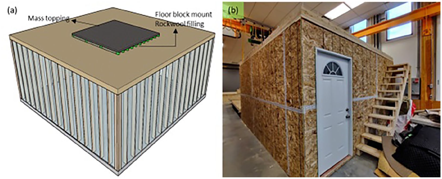
Schematic illustration of mock-up: (a) without showing drywall, insulation materials and sheathing panels and (b) outside view.
Results and discussions
Rasied discrete floating floor with precast concrete toppings
Table 1 summarizes the AIIC single number ratings for AFB raised discrete floating floors as well as three selected continuous floating floor assemblies on mass timber floor previously tested. 36 With only AFB raised discrete floating floor on the bare CLT floor, the AIIC rating increases from 21 to 47. This basic assembly without a mass topping has higher AIIC rating than that of most of the continuous floating concrete assemblies tested on the same CLT floor. 26 The insertion of mineral wool insulation (INS) in the cavity brought AIIC another 3 points higher to 50. The addition of 38 mm concrete topping further improved the AIIC to 58, which was higher than the 55 recommended by the National Building Code of Canada. 37 The increase of concrete thickness from 38 to 100 mm could improve the impact sound insulation in the continuous floating concrete assemblies. 26 Unlike the continuous floating concrete floor method, the increase of concrete topping thickness does not affect much on AIIC rating of the discrete floor assemblies. On the discrete raised floor, four concrete mass toppings each brought up a single number rating 1 or 2 points gradually until reaching 62 with 100 mm concrete topping. The increase of concrete thickness brings additional mass to the floating floor assembly, which lowers down the frequency of the vibration isolator. The 50 mm mass topping with engineered floor finishing was tested as a potential solution for actual construction, which was beyond the minimum fire encapsulation requirements of 38 mm concrete. The AIIC of this assembly is 59 and very close to the high impact sound insulation benchmark research, in which this number was reported to be 60. 36 In addition, the assembly with the engineered floor as surface finishing and Rothoblaas Silent Floor (SF) elastic interlayer underneath the 50 mm concrete topping each contributed an extra 3 points to the previous assembly and had the outcome of 62 as well. As discussed above, a discrete floating floor solution is possible to obtain AIIC with more than 60 on CLT.
Comparison AIIC ratings between AFB discrete floating assemblies and continuous floating concrete floors.
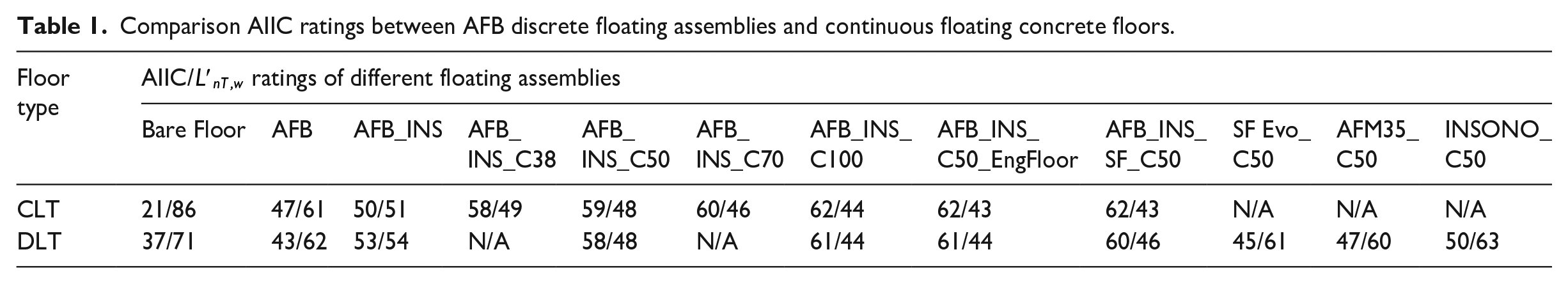
In addition to CLT, the selected assembly was tested on the DLT floor. The bare DLT floor exhibits an AIIC value that is 16 points greater than that of the bare CLT. However, the 16 points advantage of bare DLT floor than bare CLT was not maintained with the basic AFB raised discrete floor assembly. The AFB floor mounts with mineral wool filling cavity provided an AIIC of 53, which is slightly higher than the same assembly on CLT. The 50 mm concrete mass topping thickness increment on DLT brought the single number rating higher by 3 points, the same as that on CLT. The assemblies contributed with DLT and floating 100 mm concrete topping, 50 mm concrete with engineered floor finishing, and Silent Floor interlayer applying under 50 mm concrete all had AIIC rating equal or higher than 60 as well. Similar to the comparison between discrete and continuous floating floor assemblies on CLT, 36 impact sound insulation performance of the discrete and continuous floating floor were compared on DLT as well with selected elastic interlayers floating concrete toppings. These continuous floating concrete assemblies had significantly lower AIIC single number ratings than the discrete raised floor. The overall impact sound insulation performance of AFB raised discrete floating floor assemblies on CLT and DLT structural floors are similar, which means that the type of structural floor does not affect the impact sound insulation performance of the raised discrete floating floor system. Furthermore, the concrete thickness did not significantly affect the performance, indicating that dry construction boards such as cement boards and gypsum boards might be used.
The ANISPL curves of the discrete floating floor system on CLT are summarized in Figure 4(a). As can be seen, the discrete floating floor assemblies contributed significantly to both frequency regions below 315 Hz and higher than 1000 Hz. Using only AFB mounts covered by OSB, middle to high-frequency decreased the SPL for at least 25 on CLT. The Rockwool filling attenuated middle frequency sounds more effectively than extreme low or high regions on CLT. Adding a 50 mm concrete topping reduced the SPL in the low to middle-frequency (100–400 Hz) up to 20 dB. However, it has obvious drawbacks in the region above 400 Hz, as the metal hammer of the ISO tapping machine generates high-frequency noise when it falls onto the concrete surface. As a result, mass topping did not reduce SPL in the medium-to-high frequency (more than 400 Hz) as significantly as it did in the low-frequency range (lower than 400 Hz). A significant peak occurred between 400 and 630 Hz after adding the concrete topping, and that peak was not eliminated with further surface finishing. Still, installing the engineered floor can reduce the negative effect of a hard concrete surface in the frequency range higher than 400 Hz. The above observation finds that the mass topping dominates the SPL curve characteristics. The sound pressure spectra for the assemblies on DLT are shown in Figure 4(b). The bare DLT floor has a much lower peak SPL than bare CLT. The curve for DLT with AFB mounts covered by OSB has a major peak at 160 Hz and then drops linearly. The curve in Figure 4(a) shows a plateau trend in the frequency range below 400 Hz. The filling of Rockwool in the cavity had almost even contribution throughout the entire frequency domain. These differences observed on DLT revealed that the structural floor had a noticeable effect on impact sound insulation according to frequency, although the AIIC single number ratings did not show big differences in between. The curve of floating the 50 mm concrete topping on the DLT assembly demonstrates a similar characteristic to that on CLT, with a generally flatter shape. The ANISPL curve shapes with further layers of toppings beyond the 50 mm concrete are more identical on DLT than CLT. The type of structural floor did not noticeably affect the ANISPL spectra of discrete mounts floating concrete topping. In summary, the AFB discrete raised floating floors had high efficiency on impact sound insulation and demonstrated similar performance on both CLT and DLT. In the 50–100 Hz range, Figure 4(a) shows that the bare CLT floor exhibits the highest ANISPL, indicating poor low-frequency impact sound insulation. The introduction of AFB mounts reduces sound pressure levels; however, adding insulation negates this improvement. The most significant enhancement in this range is achieved with the 50 mm concrete topping, which dramatically improves ANISPL. However, the addition of the SF interlayer slightly reduces its effectiveness. In Figure 4(b), the DLT floor naturally demonstrates lower impact sound levels than CLT, with peaks at 63 Hz due to resonance effects. The discrete raised floor assemblies further improve insulation, though some residual low-frequency energy remains. The 50 mm concrete topping provides additional reduction, reinforcing its effectiveness in mitigating impact sound in this range.
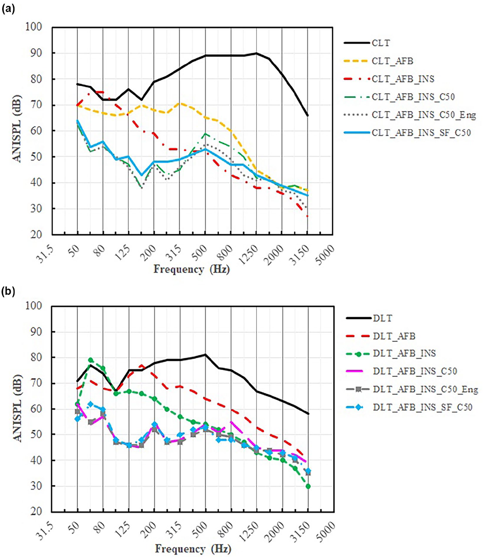
Impact sound insulation performance of discrete floating floor on: (a) CLT and (b) DLT structural floor.
As shown in Figure 5, it is obvious that the ANISPL curves for the small-scale AFB raised discrete floating concrete assembly are lower than the three continuous floating concrete floors in all the regions, while the three continuous floating concrete assemblies have similar performance. This clarifies that the raised discrete floating floor isolates the impact sound more effectively than the elastic interlayers while floating the same mass topping. The apparent dynamic stiffness is a critical quantification for elastic material, and the previous work concludes that the low dynamic stiffness material tended to have better performance on impact sound insulation. 26 With floating the 50 mm concrete topping, the load per mount is about 30 kg on AFB. According to the load versus natural frequency graph from AMC, the natural frequency is approximately 11 Hz. 23 The low natural frequency has much lower corresponding apparent dynamic stiffness than elastic interlayers. 26 Thus, the raised discrete floating floor has a much better impact sound isolation performance than continous elastic interlayers while floating the same mass topping. A peak at 63 Hz appears in the bare DLT and three continuous floating concrete assemblies, increasing ANISPL in the 50–100 Hz range. However, this peak is absent in the raised discrete floor, highlighting its effectiveness in this range. While it performs well, its efficiency is greater at frequencies above 100 Hz, suggesting potential for further optimization below this frequency range.
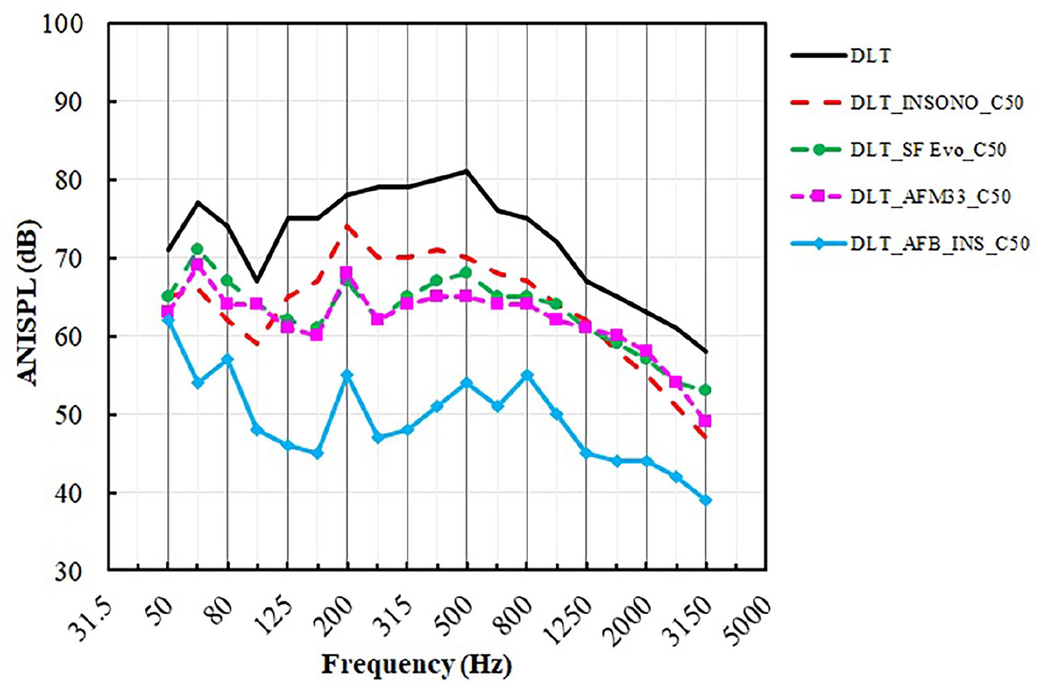
ANISPL curves of selected continuous and discrete floating floor assemblies.
Raised discrete floating floor with dry toppings
As the raised discrete floating concrete toppings have AIIC ratings of more than 60, more types of raised discrete floors with various light-weight dry toppings were tested for pursuing a more environment-friendly and lower mass assembly. The results of impact sound tests on two types of AMC innovated mounts with various low-mass toppings are discussed below. The maximum allowable load for AMC25 is approximately equal to 38 mm of concrete topping, and AMC40 has a maximum load capacity of 50 mm of normal-strength concrete. This is the main reason for only conducting the impact sound test on one concrete topping on each discrete raised floor. The bare DLT floor has an AIIC rating of 36, and the AMC25 floor mounts with OSB surface brought the single number rating higher by 11, slightly lower than AFB. With mineral wool insulation, the single number rating increases to 55. According to Table 2, double layers of cement board (CB2) floating on AMC25 reach the AIIC rating of more than 60. However, the third layer of cement board (CB3) did not contribute much to impact sound insulation performance, which also indicated that the mass increase did not contribute much to the performance. Floating double layers of cement boards would fulfill the fire resistance requirement and provide high-performance impact sound insulation solution. The finishing layer of the engineered wood floor on the AMC25 floating CB2 assembly brought the AIIC of 1 point higher. While this assembly had about only 30% of the mass of the 38 mm concrete topping, the AIIC rating was 62, which was the same as floating a 38 mm concrete topping.
AIIC rating of AMC25 and AMC40 floor block assemblies on DLT.
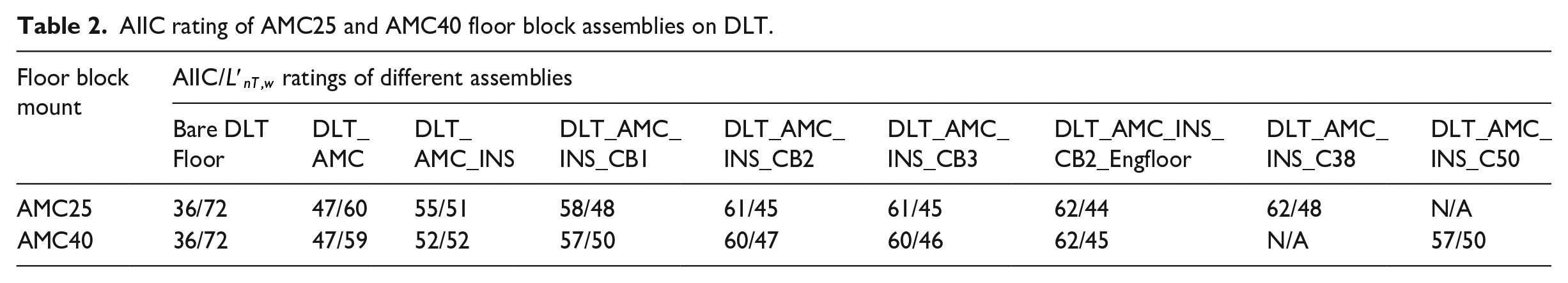
AMC40 has a higher allowable load of 40 kg/mount and can float 50 mm concrete topping. The floating 50 mm concrete topping had the same AIIC rating as a floating single layer of cement board, with the same single number rating of 57. Meanwhile, floating CB2 reached the AIIC rating of 60. Similar to the AMC25 discrete raised floor, the third layer of CB did not contribute to improving impact sound insulation performance. Comparing the impact sound insulation performance between the AMC25 and AMC40 discrete raised floor floating multiple layers of cement boards, the difference between single number ratings was below the 3 dB benchmark. The increment from single to double layer slightly increased on AIIC, and it remained the same when floating the third layer. Floating three layers of CB did not have any noticeable contribution to impact sound insulation. The advantage of higher mass for concrete topping was not favoured in the AMC25 and AMC40 discrete floating floor assemblies. However, the dry solution with cement boards demonstrated a strong impact on sound insulation performance on the discrete raised floor. Choosing an adequate floor mount corresponding to the topping load is essential in practical applications, though the difference was within the 3 dB benchmark.
The ANISPL curves of AMC25 floating 38 mm concrete topping and multiple layers of HardieBacker (CB) cement boards are shown in Figure 6. It can be seen that the AMC25 discrete floating floors are very efficient in reducing higher frequency noise than the noise below the frequency range of 160 Hz. Inserting mineral wool insulation in the cavity changed the spectrum shape and decreased the overall SPL by about 10 dB, except at 100 Hz. These two curve shapes are very similar to that of AFB on DLT in Figure 4(b). In general, with floating more layers of cement boards, the SPL at 100 Hz dropped noticeably. However, the spectra were not affected much in all other frequency bands. It is noticeable that a floating double layer of cement board has a lower SPL than a single layer throughout the frequency range. The curve shape of the floating CB differs from that of the floating 38 mm concrete topping. Although the cement board had limited performance for insulating low-frequency sound, multi-layer cement board toppings demonstrated advantages in the middle to high-frequency region than concrete toppings. Finally, the engineered floor surface finishing on the CB2 brought the curve shape slightly lower in the entire frequency range. In the 50–100 Hz range, due to heavy mass, the 38 mm concrete topping significantly reduces ANISPL but is less effective above 500 Hz due to the tapping sound on the concrete surface. Adding mineral wool insulation slightly increases ANISPL, indicating an altered dynamic response rather than improved low-frequency insulation. While the engineered floor surface finishing on CB2 performs best above 500 Hz, it is less efficient in the 50–100 Hz range. These findings suggest that mass is the key factor for lower frequencies than 100 Hz for impact sound isolation, whereas material composition becomes more critical at higher frequencies.
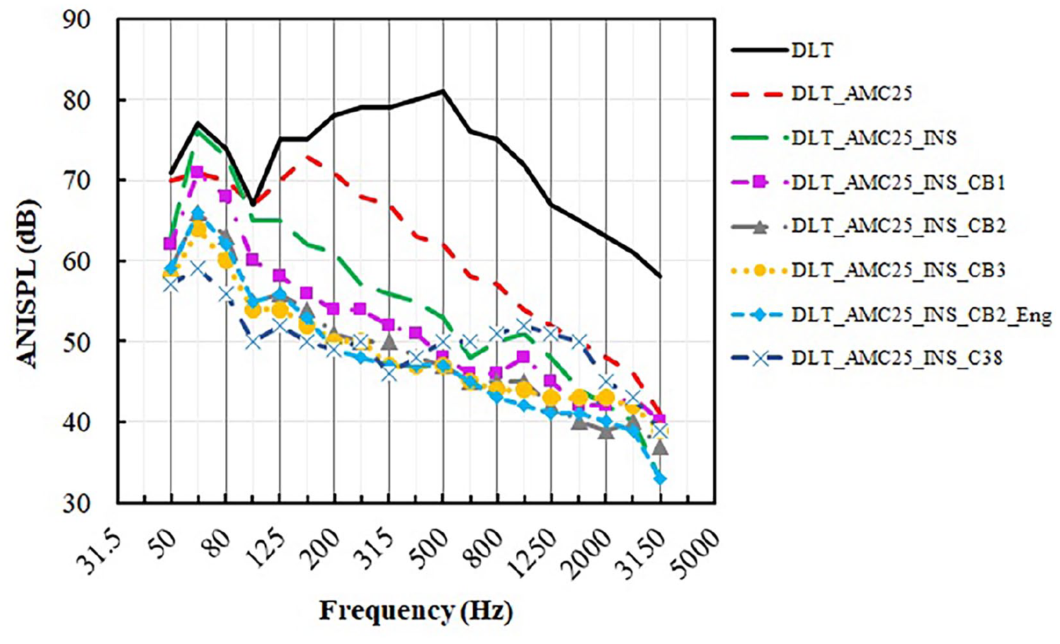
ANISPL curves for AMC25 assemblies.
The ANISPL curves for AMC40 discrete floating floor assemblies are summarized in Figure 7. Similar to AMC25, the AMC40 assemblies show high ANISPL in the 50–100 Hz range. Mineral wool insulation slightly increases ANISPL, while cement board layers provide some reduction but are less effective. The 50 mm concrete topping remains the best performer, confirming that mass is the key factor for improving impact sound insulation below 100 Hz.
In Figure 7, the curves show characteristics and observations similar to those in Figure 6. Similar to a floating 38 mm concrete topping, the curve shape of a floating 50 mm concrete topping differed from that of a floating cement board. With the higher mass from the 50 mm concrete topping, the curve profile became much lower than that of 38 mm in the frequency region lower than 160 Hz, leaving the tapping sound on the concrete surface in the middle to a high frequency not being well isolated. Also, the curve of floating 38 mm concrete on AMC25 is flatter than that of floating 50 mm concrete on AMC40, so the heavier topping changed the natural frequency of the floating floor. The placement of laminated floor as surface finishing had a slightly more positive effect on the overall impact of sound insulation performance, and the sound with a frequency higher than 250 Hz dropped between 3 and 5 dB. In summary, the less stiff CB improved the impact sound insulation performance in the high-frequency range but with the drawback of being less efficient in the low-frequency range. Similar to AMC25 discrete floor assemblies, CB2 seems to be the best dry solution floating on the AMC40 discrete raised floor. The extra mass and thickness from the concrete topping did not obviously contribute to impact sound insulation on the discrete raised floor. Similar to AMC25, the AMC40 assemblies show high ANISPL in the 50–100 Hz range. Mineral wool insulation slightly increases ANISPL, while cement board layers provide some reduction but are less effective. The 50 mm concrete topping remains the best performer, confirming that mass is the key factor for improving impact sound insulation below 100 Hz.
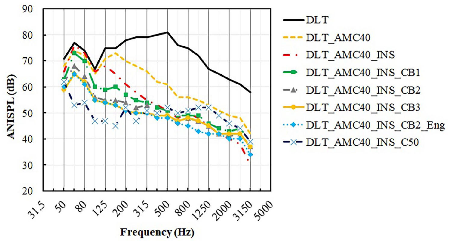
ANISPL curves for AMC40 assemblies.
The small-scale assembly tests provided preliminary results that were conservative compared to full-size assemblies, as observed in previous research on noise control in mass timber 27 constructions. While ASTM E1007-16 34 allows small-scale testing, differences in structural boundary conditions, flanking transmission effects, and load distribution between limited-size and full-size setups can influence the results. To enhance the reliability of findings, full-size impact sound tests were conducted in Table 3. The observed variations indicate that while small-scale tests can serve as an initial screening tool, full-scale measurements provide a more realistic representation of in situ acoustic performance.
AIIC rating for various discrete floating floor assemblies.
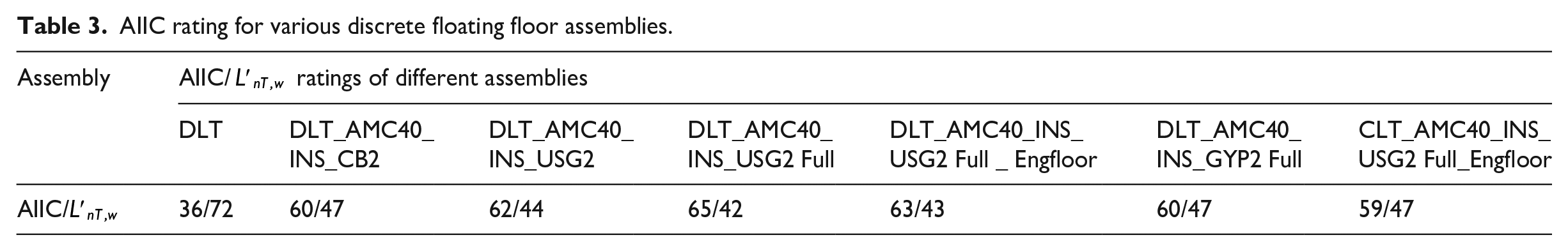
Although the USG cement board is slightly thinner and less dense than the HardieBacker one, the single number rating for a small-scale floating USG2 assembly is 2 dB higher than floating CB2. The full-size discrete floating floor covers the approximately 5.0 m × 3.6 m structural floor surface, and it contributes about 30 kg/m2 of unit load with double-layer USG cement boards or gypsum boards. The full-size raised discrete floating floor assembly reaches an AIIC rating of 65. Full-size USG2 assembly has 3 points higher than its small-scale, possibly because additional mass restrains the structural floor vibration, as well as the assembly covers the entire structural surface, minimizing airborne sound transmission. Compared with USG and CB, GYP has a slightly higher density. Except for providing about 20% less mass than USG, the GYP creates a more solid pathway for impact sound transmission. Floating GYP2 only reaches an AIIC of 60, the same as CB2 assembly. As the USG2 has the highest AIIC single number rating among the three assemblies, the final layer of the 11 mm engineered floor is applied as a surface finishing. As the laminated engineered floor has a stiffer surface, the AIIC rating drops 2 points to 63, but it is still higher than 60.
According to the ANISPL spectrum in Figure 8, floating small-scale USG2 and CB2 cement boards have similar performance below 160 Hz at about 55 dB. With the increase of frequency, the differences between the ANISPL curves of floating USG2 and CB2 grow up to 8 dB at 3150 Hz. USG2 was the dry solution with the highest performance in this study. The double layer of gypsum boards fulfilled the fire resistance requirement in tall wood buildings according to the latest Canadian fire code. 30 The double-layer USG cement board and gypsum board (GYP2) were installed as a mass topping on the full-size AMC40 discrete floating floor. The impact sound curve of the full-size floating USG2 assembly had a lower profile with the increase of frequency band than the small-scale one. Although the total mass on the DLT structural floor increased significantly, the unit mass of the floating floor was not necessarily changed. This supported the finding that heavier unit mass floated, reducing more SPL in low-frequency, based on the discussions on AFB floating concrete toppings.
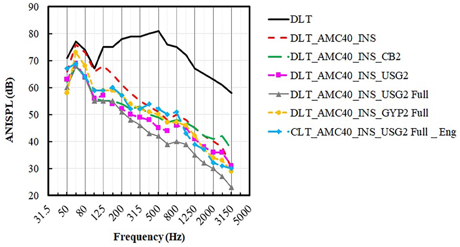
ANISPL curves of multiple full-sized assemblies.
Figure 8 shows that the full-size USG2 has about 8 dB lower SPL than full-size GYP2 in the entire frequency domain. This finding matches the AIIC single number rating in Table 3. The full-size AMC 40 floating USG2 assembly was tested on CLT with an engineered finished floor, yielding an SPL approximately 5 dB higher than that observed on DLT. However, this assembly still had an AIIC of 59. In summary, with increasing frequency, the full-size discrete raised floating floor showed better performance on impact sound insulation. If a background noise level of 40 dB was considered the benchmark of “quiet” in a room, the impact sound with a frequency higher than 630 Hz was considered insulated by the AMC40 discrete raised floor with a double layer of USG cement boards. The impact sound test results with small-scale assemblies allowed by ASTM E1007-16 were considered conservative. The USG2-based configurations exhibit the lowest ANISPL between 63 and 100 Hz, indicating superior impact sound insulation in this range. However, below 63 Hz, the trend shifts, likely due to resonance effects, resulting in GYP2 demonstrating the best performance at 50 Hz. This suggests that while USG2 is more effective in the upper portion of the 50–100 Hz range, GYP2 provides better performance at 50 Hz, highlighting the influence of material properties and system dynamics on low-frequency sound insulation.
Conclusion
This study investigated the impact sound insulation performance of raised discrete floating floor on mass timber floors under ASTM E1007-16 with ISO tapping machine excitations. Multiple dry gypsum and cement boards were floated as a mass topping as an alternative solution to the pre-cast or cast-in-place concrete toppings, and the full-size dry solution assemblies were tested for comparison with the small-scale tests. The major conclusions are listed below:
The raised discrete floating floor is considered an effective method to isolate impact sound on the mass timber floors. The raised discrete floor system with all three types of floor block mounts was able to reach an AIIC of more than 60. The type of structural floor (CLT and DLT) did not have a strong effect on impact sound insulation performance, and the thickness of the concrete topping was not critical in improving the AIIC ratings.
The comparison between AMC25 and AMC40 floor mounts concluded that the load capacity of the floor block mounts had a minor influence on impact sound insulation performance, and the raised discrete floating floors had similar SPL curve characteristics. Floating dry toppings had similar SNQs as floating concrete toppings, and they can isolate middle to high frequency impact sound more effectively.
The small-scale assembly had 3 points lower in single number rating than the full-size assembly on the DLT floor. The small-scale floating floor assembly in the impact sound test was a conservative evaluation process which can be used for preliminary or screening tests.
In the frequency range from 50 to 100 Hz, the behaviour was found to be different from higher frequency ranges, requiring separate improvements. The resonance, peak frequencies, and ANISPL amplitude in this range were highly dependent on the mass of the topping, and the vibration isolation system showed less improvement in this frequency range. This highlights the need for specific design adjustments to enhance impact sound insulation performance within this band. Additionally, further research is suggested for the broader 20–100 Hz range, which includes the peak impact sound levels induced by footfalls and heavy weight excitations.
Footnotes
Acknowledgements
We acknowledge the in-kind contributions from StructureCraft, Structurlam, Getzner, and AMC Mecanocaucho, as well as the technical support from the Wood Innovation Research Lab at UNBC.
Declaration of conflicting interests
The author(s) declared no potential conflicts of interest with respect to the research, authorship, and/or publication of this article.
Funding
The author(s) disclosed receipt of the following financial support for the research, authorship, and/or publication of this article: The financial support from BC Forestry Innovation Investment -Wood First program, the Natural Sciences, and Engineering Research Council of Canada (NSERC) and the University of Northern British Columbia (UNBC) is greatly acknowledged.