
Abstract
Porous materials such a melamine foam are commonly used to absorb noise and to control reverberation time in buildings. However, the ability of a thin porous layer to absorb noise at acoustic wavelengths that is much greater than the layer thickness is limited. This work investigates theoretically and experimentally the influence of a very thin, natural cellulose membrane on the sound absorption coefficient of a melamine foam substrate. The experimental results demonstrate that the presence of a 120 μm cellulose membrane can more than double the sound absorption coefficient of a relatively thin (17.4 mm) layer of melamine foam at frequencies above 600 Hz (577 mm wavelength). The theoretical part of work explains this effect through a careful simulation. The results show that there are analytical models that can accurately predict the acoustical behaviour of the cellulose membrane combined with a layer of melamine foam. The effects of the flow resistivity and thickness of a cellulose fibre membrane on the acoustic absorption coefficient of the melamine foam substrate are also studied through modelling and experiment. It is found that the optimum thickness of the cellulose fibre membrane should be between 75 and 100 µm when laminated on the top of a 20 mm melamine foam substrate. This work suggests that thin layers of sustainable natural materials such as cellulose fibres can be used to significantly improve the ability of traditional porous media to absorb sound.
Keywords
Introduction
In Europe, more than 100 million people are exposed to noise every year with clear evidence for adverse health and well-being effects. 1 Since the 1960s, noise has evolved from a public health matter to a global environmental pollution issue with the development of industrialisation and urbanisation. It has a significant impact on human and animal life activities. Evidence from studies on how noise effects human health at both the sound pressure level and frequency level shows that it causes hearing loss, 2 annoyance, 3 endocrine disorders, 4 insomnia 5 and cardiovascular disease. 6 The use of porous materials is a cost-effective way to control noise in buildings, transportation and industry. 7 In general, a thin layer of porous material has a poor sound absorption when the frequency of sound is low, but their ability to absorb sound improves with the increased material thickness as it becomes comparable to the acoustic wavelength. It is known that the presence of a resistive screen (i.e. thin porous membrane) can increase the sound absorption capacity of a traditional porous layer without increasing its thickness and weight. 8 This effect has significant implications for reducing energy consumption and carbon emissions in the manufacture of efficient acoustic absorbing materials.
A comprehensive review of the research on the effect of a resistive screen composed of sub-micron synthetically produced fibres on the acoustical properties of a porous layer can be found in the PhD thesis by Hurrell.
9
This review suggests that a majority of related research has been into synthetic fibre membranes and relatively little attention has been given to natural material membranes such as those made from natural cellulose fibres. Much of the current research on natural cellulose fibre membranes has been focused on their application in water treatment,10,11 fuel cells
12
and natural gas desulphurisation,
13
and, to the best of our knowledge, no one has yet explored their potential for sound absorption. Furthermore, most previous work has only involved experimental measurements and lacked theoretical or semi-empirical models to predict the measured acoustic properties of fibrous membranes. The work reported in our paper fills the gap through a more systematic study of the acoustical properties of natural cellulose fibre membranes laminated to a melamine foam layer. The novelty of this work is that the sound absorption coefficients of melamine foam substrate and fibre membrane systems were modelled theoretically. The effects of the flow resistivity
Materials and methods
Material preparation
Natural cellulose fibre membranes were supplied by the industrial partner FiberLean® Technologies (https://fiberlean.com/) who is a leading global producer of Microfibrillated Cellulose (MFC). This technique transforms natural cellulose into smaller diameter fibre bundles. The details of this sustainable membrane manufacturing process cannot be disclosed, but it involves dilution, heating, filtration and oven drying. The skeleton density of the natural cellulose fibre is provided directly by FiberLean and is 1.67 g/cm3. Due to the large diameter of the cellulose fibre membrane provided, its sample needed to be cut to fit the impedance tube measurements. The cellulose fibre membrane was cut with scissors to fit the outer diameter of the matting surface of the impedance tube sample holder of 112 mm. Different specifications of cellulose fibre membranes were investigated in this work, as shown in Figure 1. The first, second and third columns in the photograph are for samples of 20, 30 and 80 gsm, respectively (gsm is the unit of grams per square metre).
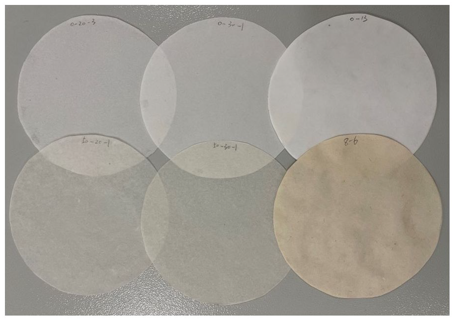
Photograph of natural cellulose fibre membranes, all with a diameter of 112 mm. The material density increases from 20 to 80 gsm from left to right.
Scanning electron microscopy (SEM) was used to study the microstructure of the cellulose fibre membranes. This displays information on fibre diameter and pore size. As the membrane is made of cellulose, it is non-conductive. When running the SEM, the sample will accumulate electrons, and imaging will be abnormal. Therefore, the sample was coated with gold. Gold coating can also prevent the heat from the electron beam during the SEM operation from damaging the fibrous structure. The Edward Sputter Coater S150B was used to coat the surface of the samples with gold around 20 nm thick. The SEM images were obtained through manipulation on a TESCAN VEGA3 electron microscope. During the SEM operation, the accelerating voltage was set to 10 kV for all samples, and the working distance was between 8.84 and 10.94 mm. Figures 2 to 4 present the SEM images of the cellulose fibres of which the membranes studied in this work were composed.
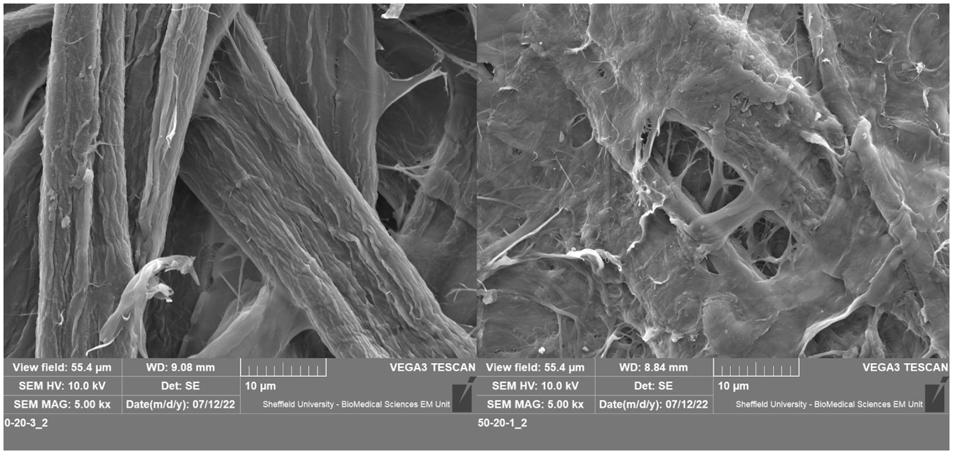
SEM images of 20 gsm membranes at a magnification of 5000. Left: 0-20-3, Right: 50-20-1.
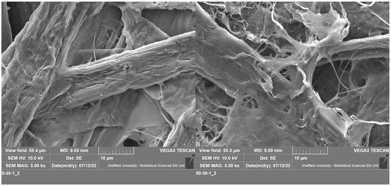
SEM images of 30 gsm membranes at a magnification of 5000. Left: 0-30-1, Right: 50-30-1.
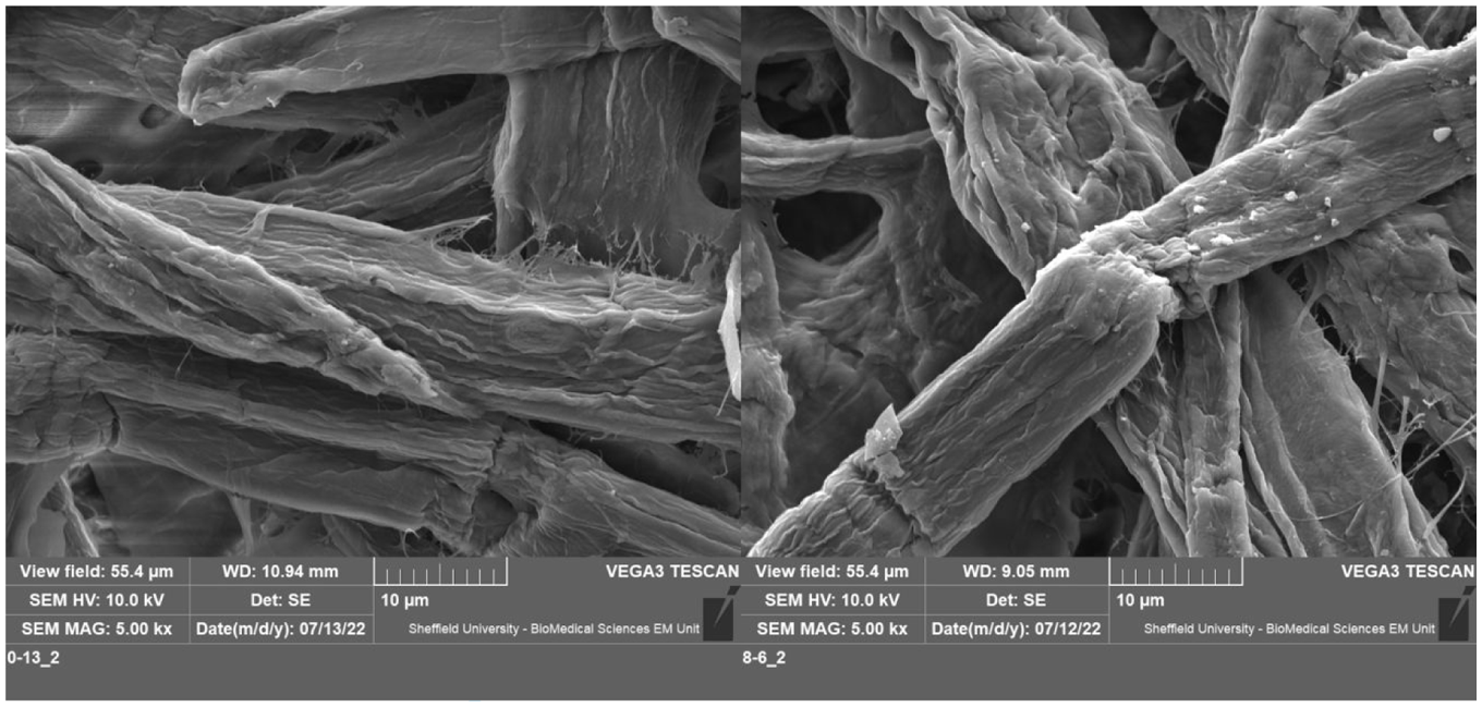
SEM images of 80 gsm membranes at a magnification of 5000. Left: 0-13, Right: 8-6.
The thickness and weight of all six cellulose fibre membranes were measured to calculate their density and porosity. As the cellulose fibre membranes are very thin, their thickness was measured using a DML digital spiral micrometre at 90° intervals along the edge of the material, four times in total. The results were then averaged. The porosity of the cellulose fibre membrane was then calculated as:
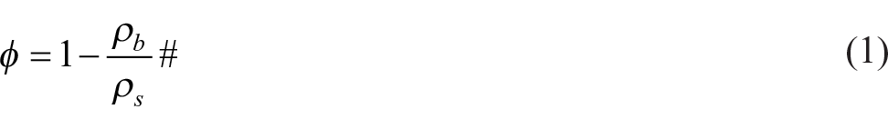
where
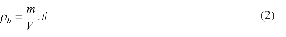
Here m is the mass of the cellulose fibre membrane and V is the volume of the cellulose fibre membrane. The mass of the cut cellulose fibre membrane was weighed on an AND HR-120 balance scale. The volume was determined from:

where r is the radius of the membrane and h is the membrane thickness. Table 1 presents a summary of the measured and calculated values of the membrane thickness, density and porosity. The standard deviation in membrane thickness comes from non-uniformity in thickness and measurement error. This is because the membranes are thin and soft and may be compressed when measured with a spiral micrometre. Except for samples 5-20-1 and 0-13, which had large standard deviations, the measurement errors in the thicknesses of the other samples were minor. The thickness of the cellulose fibre membrane increases from 20 to 80 gsm samples. As the nano-fibres were added, the porosity of the membrane decreases by 3%–16% which is logical.
Measured cellulose fibre membranes thickness and weight and calculated porosity, with standard deviations in parentheses.
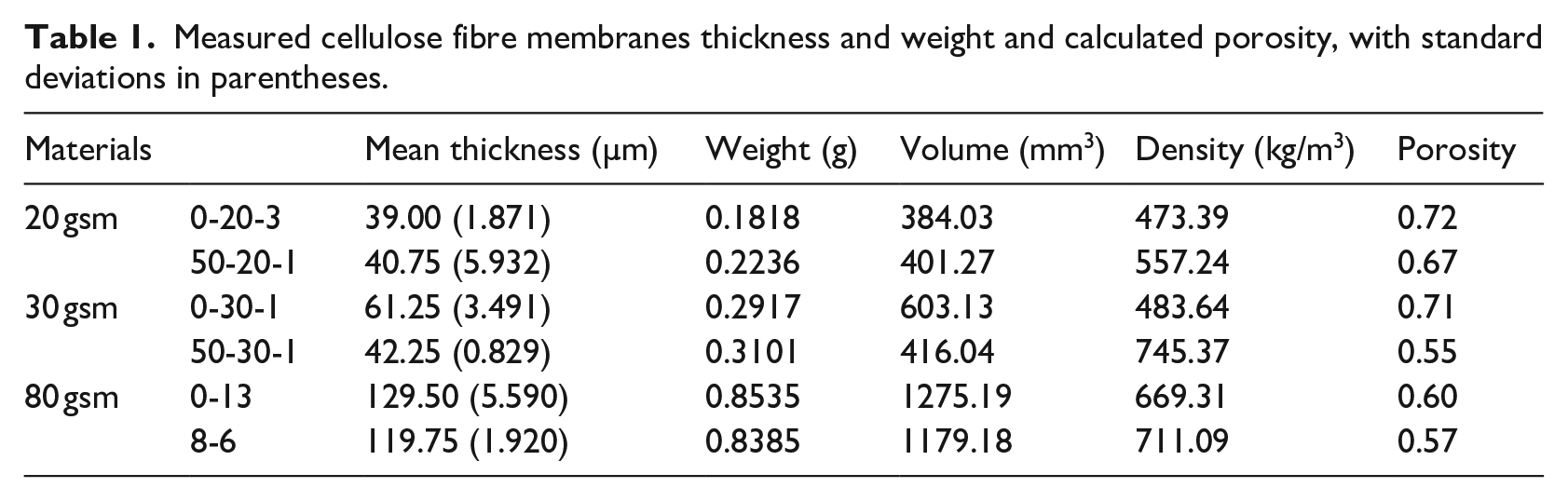
The SEM images of the 20, 30 and 80 gsm cellulose fibre membranes are shown in Figures 2 to 4, respectively. As can be seen from these figures, the cellulose fibre diameter of the 0-20-3, 0-30-1 and 0-13 membranes without added nano-fibres is similar, being approximately 10 µm. Very few sub-micron (nano-sized) fibres were present in these membranes. As the membrane surface density increases, the area occupied by the fibres appearing in the microscope also increases while the porosity decreases, which is consistent with the porosity data shown in Table 1. The porosity of the membranes with added nano-fibre dose is lower than that of the membranes without nano-fibres. It is difficult to see more nano-fibres in the SEM images of the 50-20-1, 50-30-1 and 8-6 membrane images shown in Figures 2 to 4. There are some distinct nano-fibre connections between the micron-scale fibre bundles. If examined closely, the surface of the membrane with the added nano-fibres is covered with several bonded nano-fibres, which are bonded together to form an impermeable web. The bonding of the nano-fibres is due to the formation of hydrogen bonds between the nano-fibres by water on the surface of the cellulose during oven drying, resulting in agglomeration.
Sound absorption coefficient measurement
The acoustical properties of the materials studied in this work were measured using a 100 mm impedance tube manufactured by Materiacustica (http://www.materiacustica.it/) to the standard ISO 10534-2. 14 The schematic diagram of the tube is shown in Figure 5. The frequency range of this tube was 100–1600 Hz. Each measurement was repeated three times and results were averaged.
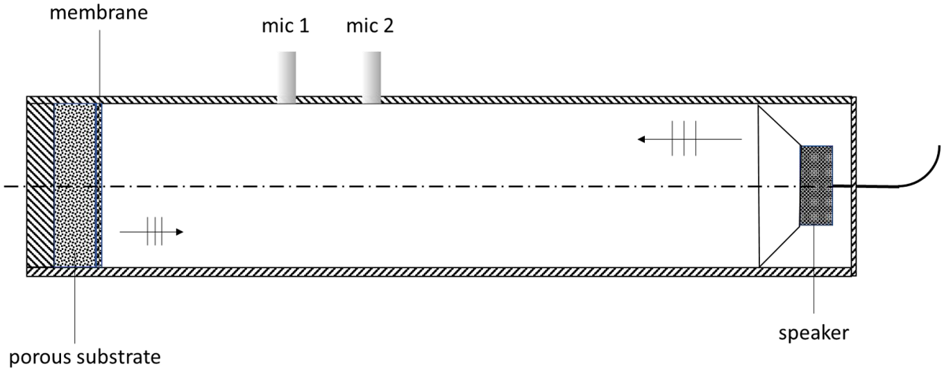
A sketch of the impedance tube setup based on the transfer function method.
Mounting of cellulose fibre membranes in the impedance tube is challenging. Cellulose fibre membranes are thin and soft enough that they can only be measured by being laminated on a porous material substrate that is self-supporting as shown schematically in Figure 5. The method of mounting must not disrupt the membrane structure and properties, therefore adhesive bonding of the membrane and melamine foam was not used because the glue could have affected the membrane’s acoustical properties. Other mounting methods, such as attaching the membrane with pins or wrapping it around the substrate can reduce the flow resistivity and overall acoustical absorption performance of this system. 15 In our work, the membrane was cut to the size of the inner diameter of the sample holder and secured with a sticky tape to the wall of the impedance tube in front of a 17.4 mm thick sample of melamine foam as shown in Figure 6. The melamine foam sample was hard-backed against the back wall of the impedance tube as schematically shown in Figure 5. Inevitably, a small air gap existed between the foam layer and cellulose membrane. Another air gap was between the wall of the impedance tube and membrane edge. These air gaps were very small, but impossible to avoid. Their effects are modelled as detailed in the following section.
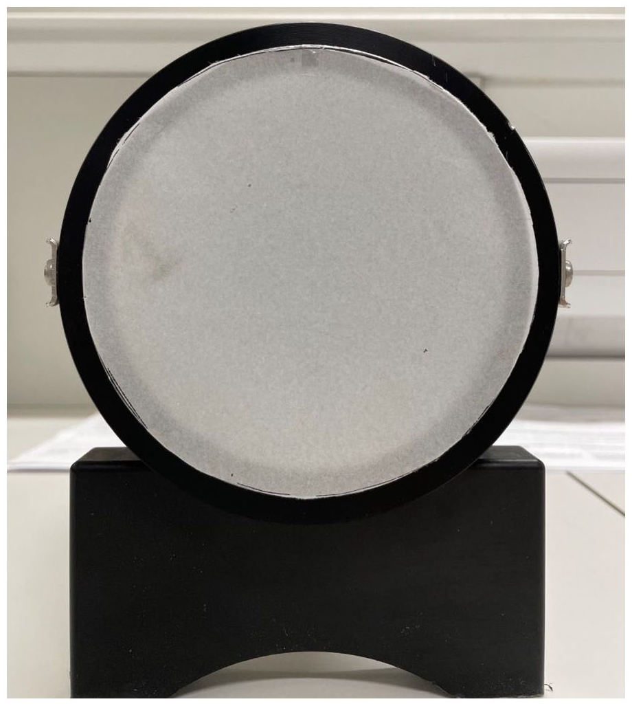
A membrane is cut to 112 mm diameter and placed on a substrate in the tube. Tape is applied to the edges of the membrane to hold it in position.
Modelling
In order to simulate the experimentally measured sound absorption coefficients of cellulose fibre membranes laminated to melamine foam (porous substrate in Figure 5), the right models need to be selected. In addition, because the sound absorption coefficient was measured in the impedance tube using small material specimens, the results are likely to be affected by the air gap between the membrane and porous substrate and circumferential air gap between the membrane edge and impedance tube. Therefore, the effects of these air gaps were studied through simulations. The effect of the air gap between the porous substrate and membrane was found relatively small in comparison of that from the circumferential air gap so that it was not simulated.
Simulation of melamine foam substrate
There are many models available to simulate the sound absorption coefficient of melamine foam. In this work we applied a three-parameter model proposed by Horoshenkov et al. 16 This model relates the porosity, median pore size and standard deviation in the pore size distribution to the characteristic acoustic impedance and complex wavenumber for sound propagation in a porous medium. The three-parameter model is attractive, especially to non-acoustic experts, as it is based on these directly measurable non-acoustical properties of porous media and incorporated in commercially available AlphaCell software 17 under the name of Arbitrary Psd model. This model is also attractive for the robust inversion of the non-acoustic parameters from the measured impedance tube data because it relies on a limited number of non-acoustical parameters. Figure 7 shows a screenshot from AlphaCell software that was used to predict the acoustical properties of the 17.4 mm thick layer of melamine foam with the adopted analytical model. 16
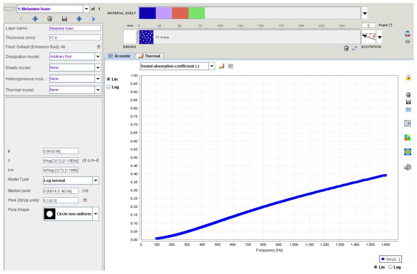
An example of the AlphaCell interface. The top left panel is for adding materials to the impedance tube and material shelf and selecting the acoustic model. The bottom left panel is for model input. In the middle is the simulation graph of the sound absorption coefficient. The right panel is for exporting the simulation data.
Simulation of cellulose fibre membranes
Cellulose fibre membrane is a screen type material with very high flow resistance. Therefore, any acoustical model for resistive screens also applies to cellulose fibre membranes. In this work a modified resistive screen model proposed by Atalla and Sgard 18 was used to simulate the acoustic response of the cellulose fibre membrane. In this model the key parameters are the membrane’s flow resistivity, density and thickness. The general screen model defined the equivalent tortuosity of the screen in terms of corrected length and dynamic tortuosity overcoming the problem when classical models do not work for materials with high flow resistivity. The flow resistivity of cellulose membranes could not be measured directly and it was estimated as the best fit parameter between the predicted and measured absorption coefficient spectra.
Furthermore, the effect of the inevitable circumferential air gap was considered by treating the membrane as a porous layer with the model proposed by Chevillotte et al. 19 The porous composite model considers viscous thermal and pressure diffusion effects and can simulate composites containing inclusions of different shapes with high permeability contrasts. In this work the only parameter in the composite model was the width of the circumferential gap between the cellulose membrane and wall of the impedance tube. It was estimated as a membrane’s thickness.
Results and discussions
Melamine foam
Figure 8 shows the measured and predicted absorption coefficient of the 17.4 mm melamine foam substrate. The values of the three parameters used in this simulation were fitted using the minimisation procedure described in AlphaCell software.
17
The inverted porosity of melamine foam was
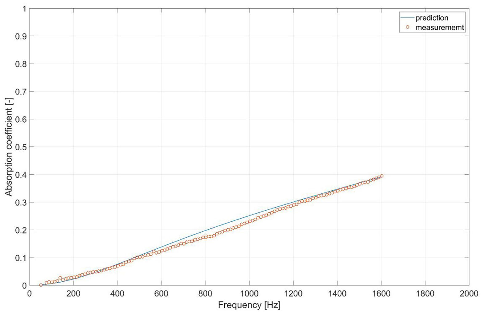
The absorption coefficient spectra of the 17.4 mm layer of melamine foam measured in the 100 mm impedance tube and predicted with the three-parameter model. 17
Melamine foam with cellulose fibre membrane
The measured sound absorption coefficients of six cellulose fibre membranes laminated to melamine foam are presented in Figure 9. It also presents the absorption coefficient of the melamine foam layer without any membrane as a comparison. As the thickness of the 20 and 30 gsm membranes is comparable with the standard deviation in the melamine foam thickness, this results in the inevitable air gap between the membrane and the substrate. Under the acoustic excitation the membrane vibrates. Furthermore, as the position of the melamine foam in the sample holder was controlled manually by adjusting of the scale-free piston at the rear end of the sample holder, this resulted in a different degree of fitting the foam substrate to the fibre membrane for each experiment. The mounting conditions of the membrane, air gap between the membrane and substrate, and circumferential air gap caused the measured data for the cellulose fibre membranes to fluctuate. This is shown with the error bars in Figure 9 that correspond to the standard deviation in the measured absorption coefficient spectra.
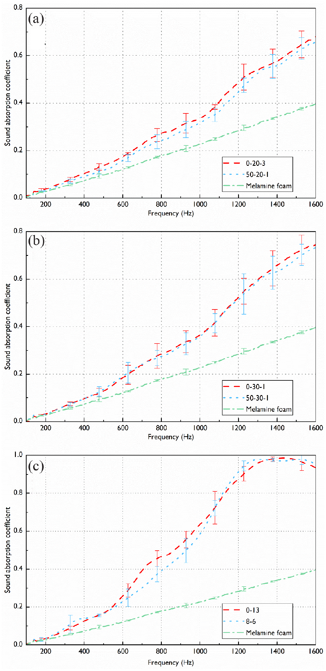
The measured sound absorption coefficient of the 17.4 mm layer of melamine foam without (green dash-dot lines) and with the following cellulose fibre membranes (red and blue dashed lines): (a) 20 gsm, (b) 30 gsm, and (c) 80 gsm.
The results shown in Figure 9 suggest that the presence of the cellulose fibre membranes significantly improves the sound absorption of the layer of melamine foam. The addition of the 20 and 30 gsm cellulose fibre membranes results in a more than two-fold increase in the acoustic absorption coefficient at frequencies above 1200 Hz. These membranes are only 40–60 μm thick. The addition of the 80 gsm membranes to the melamine foam substrate increases its absorption coefficient by a factor of 2 at frequencies above 600 Hz. At frequencies above 1400 Hz this effect is three-fold. This increase in absorption is substantial given the fact that these membranes are only 120–130 μm thick. The physics behind this effect is explained in Hurrell et al. 15 Here, the addition of a thin, highly resistive membrane increases the real part of the acoustic surface impedance of the melamine foam substrate proving a better acoustic match for the incident sound wave. These composite materials are well suited for noise control in buildings and on transport where the typical noise level spectra peak around 500−1000 Hz and where space for installing thick layers is limited.
It is difficult to determine from Figure 9 whether the increase in the proportion of nano-fibres has improved the sound absorption of the membrane/melamine foam system. The reasons for this phenomenon are twofold. Firstly, the addition of nano-fibres to the membrane does not actually form a distinct nano-fibre patten that is substantial enough to alter the acoustical properties of the network of pores formed by cellulose. This is illustrated by the SEM images in Figures 2 to 4. The nano-fibres are bonded into an impermeable web that covers the surface of the membrane and that is too thin to make a measurable effect. Secondly, the thickness of the same samples with different nano-fibre proportions (e.g. 0-30-1 and 50-30-1) varies and thickness is one of the factors affecting the sound absorption of the membrane/melamine foam system.
Simulation fitting of cellulose fibre membranes
The simulation was carried out for membranes 0-20-3, 0-30-1 and 0-13 placed on the top of the layer of melamine foam. AlphaCell software was used to predict the absorption spectra of these three material systems. The values of the parameters used to model the acoustical properties of the melamine foam layer backing the membrane were taken as quoted in the previous section. The membrane density, porosity and thickness were measured and taken from Table 1. The membrane flow resistivity was fitted to minimise the difference between the measured absorption coefficient spectra and those predicted using the models adopted from Horoshenkov et al. 16 and Atalla and Sgard. 18 The effect of circumferential air gap was small in the case of membranes 0-20-3 and 0-30-1 to influence noticeably the acoustical properties of the melamine foam/cellulose membrane system. In the case of membrane 0-13 this effect was noticeable and modelled using the method proposed in Chevillotte et al. 19 for a 65 μm thick circumferential air gap (one-half of the membrane thickness). Table 2 displays the parameters used to model the acoustic absorption coefficient of the three membrane systems. The simulation suggests that the flow resistivity of the membranes becomes progressively higher as the membrane density increases. This makes physical sense and it was reported in Hurrell et al. 15 Figure 10 shows a comparison between the measured and predicted absorption coefficient spectra for the three melamine foam/membrane systems.
The input parameter values of membranes used to predict the absorption coefficient of the membrane/melamine foam system.
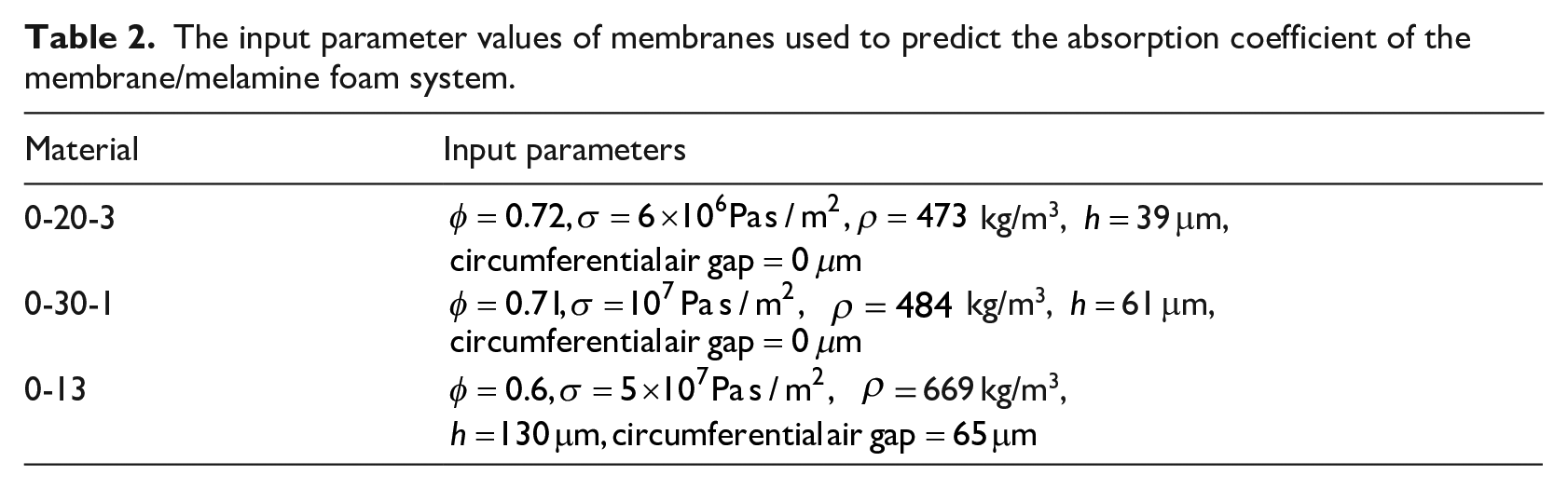
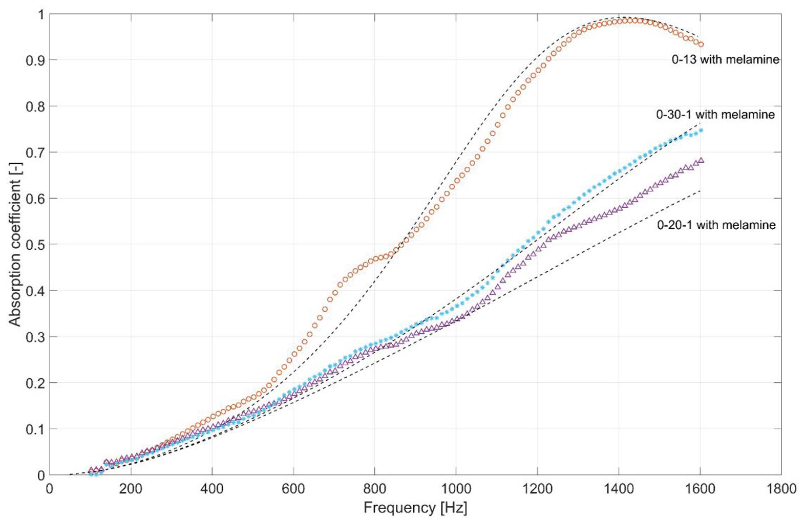
The measured (marker) and predicted (dashed line) absorption coefficient spectra of the melamine foam layer with a cellulose membrane.
Several observations can be made from these results. Firstly, as the flow resistivity of the membrane and its thickness becomes greater, the absorption coefficient of the melamine foam/cellulose membrane system becomes higher. In this case the effects of the circumferential air gap becomes more pronounced and it needs to be accounted for. This enables to predict the acoustic absorption coefficient with the mean error of better than 1%. Secondly, there is little difference between the absorption coefficient spectra of membrane 0-30-1 and 0-20-3 acoustic systems. This can be explained by their relatively close value of the non-acoustical parameters such as density, thickness and flow resistivity. Thirdly, as the membrane thickness reduces, it makes more difficult to predict accurately the acoustic absorption coefficient of this system. Therefore, there is a stronger discrepancy between the measured and predicted absorption coefficient spectra for membrane 0-20-3. The mean error between the predicted and measured absorption coefficient spectrum for the 0-20-3 membrane on the melamine foam layer is 3% with the maximum error being 6% at 1600 Hz. This discrepancy cannot be reduced by changing the flow resistivity value or adding any circumferential air gap. The prediction can only be made more accurate by increasing the membrane thickness by 20%. It was reported in Hurrell et al. 15 that it is rather difficult to estimate accurately the true thickness of thin membranes that got compacted when a micrometre device is used on fibrous membranes with a relatively low stiffness. Also, the classical model 18 may no longer work accurately when the membrane’s thickness become comparable with the viscous boundary layer thickness. 15 There is a need for a better model to predict the acoustical properties of thin, highly resistive screens.
Parameter effects on sound absorption of cellulose fibre membranes
It is of interest to simulate the effect of key non-acoustical parameters on the ability of cellulose fibre membrane in combination with a porous substrate to absorb sound. This part presents the results of such a simulation carried out with AlphaCell software.
Figure 11 illustrates the effect of the flow resistivity of a 50 μm thick cellulose fibre membrane on the acoustic properties of the membrane laminated to a 20 mm melamine foam substrate. The simulations used classic melamine foam with a thickness of 20 mm, mean pore size of 140 µm and pore size standard deviation of 0.3. The simulations excluded the effects of the air gap and circumferential air gap. It is obviously that an increase in the flow resistivity of the membrane increases the sound absorption coefficient of the cellulose fibre membrane and melamine foam layer. However, as flow resistivity increases, the benefit of the improved sound absorption coefficient reduces eventually. This indicates there is an upper limit to the flow resistivity above which there will be no effect on the sound absorption of the membrane. This is consistent with the findings of Cao et al. 20 who found that the increase in the flow resistivity of nano-fibre aerogels with a layered labyrinth structure significantly enhanced sound absorption up to a point.
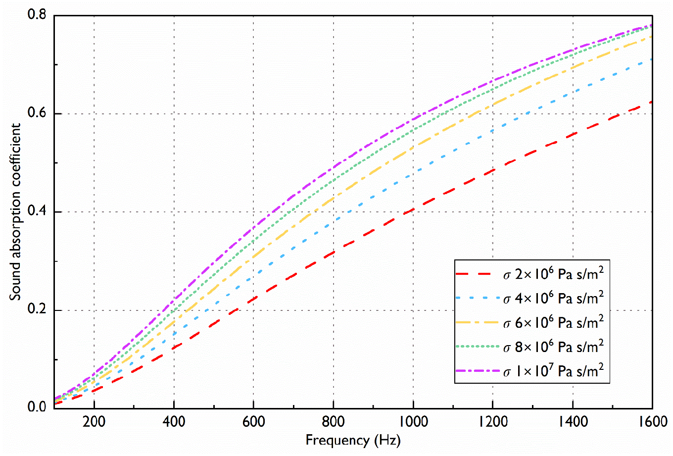
The effect of the membrane flow resistivity on the sound absorption coefficient of a 50 µm membrane laminated to a 20 mm melamine foam layer.
The effect of thickness of the cellulose fibre membrane on its sound absorption coefficient is presented in Figure 12. As can be seen from the figure, the most significant improvement in sound absorption is obtained by increasing the thickness of the cellulose fibre membrane from 25 to 50 µm. The best sound absorption is achieved at membrane thicknesses of 75–100 µm. As the membrane thickness is increased to 150 µm, sound absorption below 800 Hz continues to improve, but decreases from 850 Hz onwards. A resonance peak in the absorption spectrum is expected to occur with any further increases in membrane thickness.
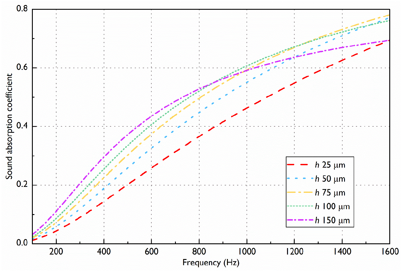
The effect of the membrane thickness on the sound absorption coefficient of a membrane with a flow resistivity of 7 × 10⁶ Pa·s/m2 laminated to a 20 mm melamine foam layer.
Conclusions
To the best of our knowledge there has been no or limited work on the acoustic properties of natural cellulose fibre membranes. In response to this, a study of the acoustical properties of natural cellulose membranes attached to a layer of melamine foam has been carried out. These materials have been carefully characterised in the laboratory at the University of Sheffield to determine the values of key parameters that affect their acoustical properties. Some parameters have been measured directly. An impedance tube has been used to measure the acoustical properties of a layer of melamine foam with and without membrane attached to its front surface. The parameter inversion procedure suggested in Horoshenkov et al. 16 has been used to estimate the values of those non-acoustical parameters of melamine foam and cellulose membranes that are difficult or impossible to measure directly. In the case of melamine foam these parameters are the median pore size and pore size standard deviation. In the case of cellulose membrane this parameter is the flow resistivity. The parameter inversion provides a quick and easy way to estimate key non-acoustic parameters of a material.
A natural cellulose fibre membrane attached to a melamine foam substrate can significantly improve the acoustic absorption coefficient of the melamine foam layer. In particular, a 120 µm thick cellulose fibre membrane laminated to a 17.4 mm thick melamine foam layer can increase the acoustic absorption coefficient by a factor of 3 at 1600 Hz. Cellulose fibre membranes are very light, for example, less than 90 g/m2, and thin, for example, less than 120 μm, so that they do not add much mass or thickness to the layer of substrate, but improve its acoustic absorption capability significantly.
An acoustic simulation has been carried out to predict the measured acoustic absorption spectra. The acoustical properties of melamine foam have been predicted using the three-parameter model. 16 The acoustical properties of the resistive membrane made of cellulose fibres have been predicted using the screen and porous composite models.17,18 It has been shown that these models can accurately predict the acoustic absorption coefficients of 30 and 80 gsm cellulose fibre membranes. In the case of the 20 gsm (material 0-20-3) membrane the model has slightly underpredicted the measured absorption coefficient spectrum. It has been impossible to fit this model without increasing the membrane thickness. The 20 gsm membrane is very thin (39 μm) and relatively light (473 kg/m3). As a result, measuring its thickness accurately can be problematic as noted in the work by Horoshenkov et al. 15
The effects of the flow resistivity and thickness of the cellulose fibre membrane on its sound absorption have been investigated further through a parametric study. Increasing the flow resistivity and thickness of cellulose fibre membranes leads to an increase in sound absorption. However, there are upper limits for these two parameters above which there seems no improvement in sound absorption. For a 20 mm melamine foam substrate the optimum thickness of a cellulose fibre membrane should be between 75 and 100 µm, and further increases in thickness will shift the sound absorption curve towards lower frequencies or even create a resonance peak. This is a valuable reference for the development of cellulose fibre membranes to be used in noise control applications. In the future, the drying process of cellulose fibre membranes with added nano-fibre doses needs to be improved to ensure that the nano-fibres make a positive contribution to sound absorption.
Cellulose fibre materials are natural, so that they can be resourced sustainably to use for sound insulation in cars, buildings or industry. In this way the volume of the porous materials required to achieve a particular acoustic performance in a limited space can be significantly reduced. Furthermore, natural cellulose fibre membranes are environmentally friendly, biodegradable and relatively inexpensive making them attractive alternatives to more traditionally used man-made resistive screens.
The data presented in this paper, Matlab code used, SEM photos and copes of the graphs are available through this Google folder depository: https://drive.google.com/drive/folders/1kaoCsyzC_oVKX7AEpNTQMonv19LaZM-r?usp=share_link.
Footnotes
Acknowledgements
The authors would like to thank our industrial partner FiberLean technologies and Yun Jin for providing information about natural cellulose fibre membranes. We extend our thanks to Dr. Hasina Begum, Mathew Hall and Chris Hill for laboratory assistance. We also grateful to Prof. Abigail L. Bristow for her helpful comments on the manuscript. For the purpose of open access, the author has applied a ‘Creative Commons Attribution (CC BY) licence to any Author Accepted Manuscript version arising’.
Declaration of conflicting interests
The author(s) declared no potential conflicts of interest with respect to the research, authorship, and/or publication of this article.
Funding
The author(s) received no financial support for the research, authorship, and/or publication of this article.