
Abstract
Dry sump lubrication is a key feature in transmission systems of high-performance racing applications. While it provides adequate oil for gears contact, it reduces churning losses. Moreover, provision of continuous oil for gear contacts under harsh conditions during a race, makes dry sump lubrication systems more reliable. One of the most important aspects of any dry sump system is the assessment of its thermo-tribological performance and its capability to remove the generated heat from highly loaded high-shear gear contacts. In this paper, a multi-physics integrated numerical method of a dry sump transmission, considering a system approach is presented. The method provides a validated predictive tool to assess thermal functioning of dry sump lubrication systems.
Introduction
Ultra-high-speed gears are frequently utilized in a variety of gear systems. Several studies have investigated such gear applications. Matsumoto et al. 1 conducted an experimental study to measure the temperature field of ultra-high-speed gears (around 24,000 r/min). They also developed a numerical method to predict the temperature field. 2 Recently, Dobiáš et al. 3 investigated the temperature and stress field of high-speed helical gears numerically. The developed numerical model can evaluate gear contacts at a speed of 40,000 r/min.
Racing cars’ transmission is another example of relatively ultra-high-speed gear application. Lubrication of the transmission system in high-performance racing application is a complex matter. Gears are rotating at speeds around 11,000 r/min, and the vehicle repeatedly experiences high centrifugal acceleration. Considering these concerns, a dry sump lubrication system can be utilised as a reliable and efficient lubrication method for transmissions of high-performance racing cars. The oil jets are designed to continuously feed the lubricant into the highly loaded high-shear contacts. This is particularly important when racing vehicles corner under high centrifugal acceleration (e.g. up to 6g).
From the efficiency point of view, it reduces or eliminates oil churning as the main source of load-independent losses, which contributes to around 10% of total system losses. 4 A considerable amount of literature has been published on churning losses.5–7 Changenet and Velex 5 developed a method to predict churning losses in gear systems. The model was validated by a large number of experimental measurements. Koffel et al. 6 developed a method called the thermal network method, which takes into account the effect of load-dependent (contact losses) and no-load-dependent (churning losses) to evaluate temperature distribution in a geared transmission. Neurouth et al. 7 conducted an experimental study to investigate the feasibility of utilizing a splash lubrication system in ultra-high-speed gear systems. They introduced moveable walls (flanges) around the rotating gear in a test rig which can reduce churning losses significantly at higher speeds.
Unlike a wet (or splash) lubrication system, the oil is scavenged from the sump and returned to the oil galleries in a dry sump lubrication system. Thus, it prevents splashing the oil within the transmission system and consequently reduces churning losses. Moss et al. 8 conducted an experimental study to investigate the effect of different lubrication methods on power loss and durability of gear contacts. They concluded that the jet-lubricated method can reduce churning losses by up to 55% while resulting in similar contact losses to the wet lubrication method. Contact fatigue measurements also did not show a considerable difference between the two lubrication methods. A similar experimental study was performed by Andersson et al. 9 to compare the efficiency and temperature of gears in spray (dry) and dip (wet) lubrication systems. They concluded that a spray lubrication system results in remarkably higher total gearbox efficiency at higher speeds. Higher tooth temperature was measured using spray lubrication. However, the similarly measured surface roughness of the tooth surface after the test indicates that the durability of transmission is not affected by the lubrication system.
A considerable amount of literature has been published on oil jet impingement phenomena in gear contacts. Akin and Townsend10–14 presented pioneering studies in this field. They have conducted a series of experimental and analytical works to investigate different parameters and their effects on oil penetration depth into gear tooth space. The studied parameters were oil jet pressure and velocity, gear speed and gear tooth modifications considering jet impingement out-of-mesh or into-mesh conditions. Recently, more sophisticated numerical studies have been done on oil jet impingement flow on rotating gear. Fondelli et al. 15 developed a computational fluid dynamics (CFD) model using the volume of fluid (VOF) method to investigate the oil flow of oil jet impingement to a rotating gear tooth. Similar studies were conducted by Ambrose et al. 16 and Keller et al. 17 using the lattice Boltzmann method and smoothed particle hydrodynamics simulation models, respectively.
To date, several studies have investigated the thermal behaviour of oil jet lubricated gear contacts. Early studies in this field were done by DeWinter and Blok. 18 They developed an analytical method to predict the heat dissipation rate through an impinging jet from the surface of the gears. Their formulation overestimates the film thickness in contact that resulted in a higher heat dissipation rate. Following DeWinter and Blok's analytical method, Patir and Cheng 19 introduced a finite-element method to determine the temperature distribution of spur gears, lubricated in an oil jet system. In their model, convection heat transfer was determined based on empirical equations for a heat transfer coefficient at different parts of the gear tooth. A similar approach was developed by Long et al. 20 to investigate the effects of geometrical and operational conditions as well as lubrication conditions on the surface temperature of high-speed gear teeth. Later, Fatourehchi et al. 21 determined these heat transfer coefficients more accurately using a transient multiphase CFD model.
A system approach in thermal analysis of oil jet lubricated transmissions was considered in recent studies. Renjith et al. 22 developed a CFD model to study critical parameters (i.e. oil jet flow and gear speed and temperature) effects on the thermal performance of a jet lubricated transmission system. Deshpande et al. 23 investigated different oil jet lubrication methods (i.e. impingement of oil jet into-mesh or out-of-mesh) with a CFD approach. The experimentally validated model indicated that out-of-mesh lubrication direction results in better cooling performance.
The accuracy of such thermal analyses highly depends on the method used in the determination of heat generation in contact (i.e. contact power loss) as the result of generated contact friction of meshing gear pairs. This is also known as load-dependent losses. Contact losses of different gearing systems have been investigated in several numerical and experimental studies considering the effect of gear tooth modifications (e.g. tip relief, crowning, etc.), noise, vibration and harshness and fatigue performance.24–28
The review of the available literature on the thermal analysis of jet-lubricated gears necessitates the development of more accurate computational methods. Particularly, periodic heat generation in gear contact was not considered in previous studies. Therefore, the fact that at every revolution of a gear tooth the duration of the meshing period (i.e. time period for heat generation) of the tooth is a small fraction of the time period of the rest of the revolution is neglected. This indicates that heat dissipation through convection to ambient and conduction to the adjacent gear teeth as well as the connecting shaft is the only heat transfer mechanism during the rest of tooth rotation. Considering such concerns, Fatourehchi et al. 29 recently developed a transient finite-element model of a gear tooth with a single oil jet to predict the real-time temperature distribution of the tooth under a race condition. Modelling a single gear tooth does not take into account the heat dissipation through adjacent jet-lubricated unloaded gears which required a system approach. This paper aims to investigate the effect of multiple oil jets on both loaded and unloaded gear pairs on the thermal functioning of dry sump systems. This modelling approach enables studying heat dissipation through conduction to unloaded gears. Such a system level approach of thermal analysis of dry sump lubrication has not been reported in the literature hitherto. Validation of the developed model against experimental data shows a good agreement.
Methodology
An integrated multi-physics and multi-scale method was developed to predict thermal functioning of jet lubricated high-performance transmission systems. For a meshing cycle of spur gear contact, the instantaneous radii of curvature, as well as contact surface velocities and the orthogonal meshing contact loads, are determined utilizing a finite-element-based tooth contact analysis (TCA) method.30,31 The calculated contact parameters are then inputted to a mixed-elastohydrodynamic model to evaluate meshing power loss (or generated heat) considering both viscous and boundary frictions as well as the contact temperature rise. Based on the evaluated contact temperature rise, the heat transfer coefficient in different parts of the gear tooth is obtained using a transient multiphase CFD model. Having the heat transfer coefficients and generated heat in the contact, real-time temperature distribution on the gear tooth is determined through a developed transient finite-element model.
Tooth contact analysis
Due to efficiency and durability concerns in gearing systems of high-performance transmissions, it is essential to have various micro-geometrical tooth modifications. It was shown that tooth modifications have a considerable effect on the generated heat in contact. 25 This necessitates the use of an accurate TCA in thermal analysis of such gear systems. In this study, a finite-element-based software, CALYX, based on the method developed by Vijayakar 31 and Xu and Kahraman 32 is used to perform TCA.
Determination of the generated heat in contact
Gears in high-performance transmission applications experience extreme contact load (over 20 kN). This leads to high contact pressure and consequently thin elastohydrodynamic films, which are of the same order of asperity heights on the contacting surface.
33
Operating under mixed regimes of lubrication indicates that both viscous and boundary frictions are generated. Hence, the instantaneous power loss can be calculated as follows:

Viscous friction
The viscous friction due to shear in the lubricant film is calculated as follows: The value of α, the pressure viscosity coefficient, is assumed constant. The viscosity–pressure relationship of the lubricant under the operating condition is based on the Roelands equation.
36
The same approach was used in Chittenden et al.
35
numerical method that resulted in equation (4). The density–pressure relationship is based on Dowson and Higginson
37
formulation, which was also taken into account in equation (4).
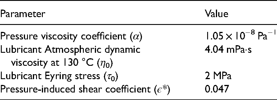
A fully synthetic transmission oil is utilized. Table 1 shows the lubricant properties obtained from the transmission oil.

Lubricant properties.
Boundary friction
A mixed regime of lubrication is dominant if the Stribeck oil film parameter, λ, is in the region:
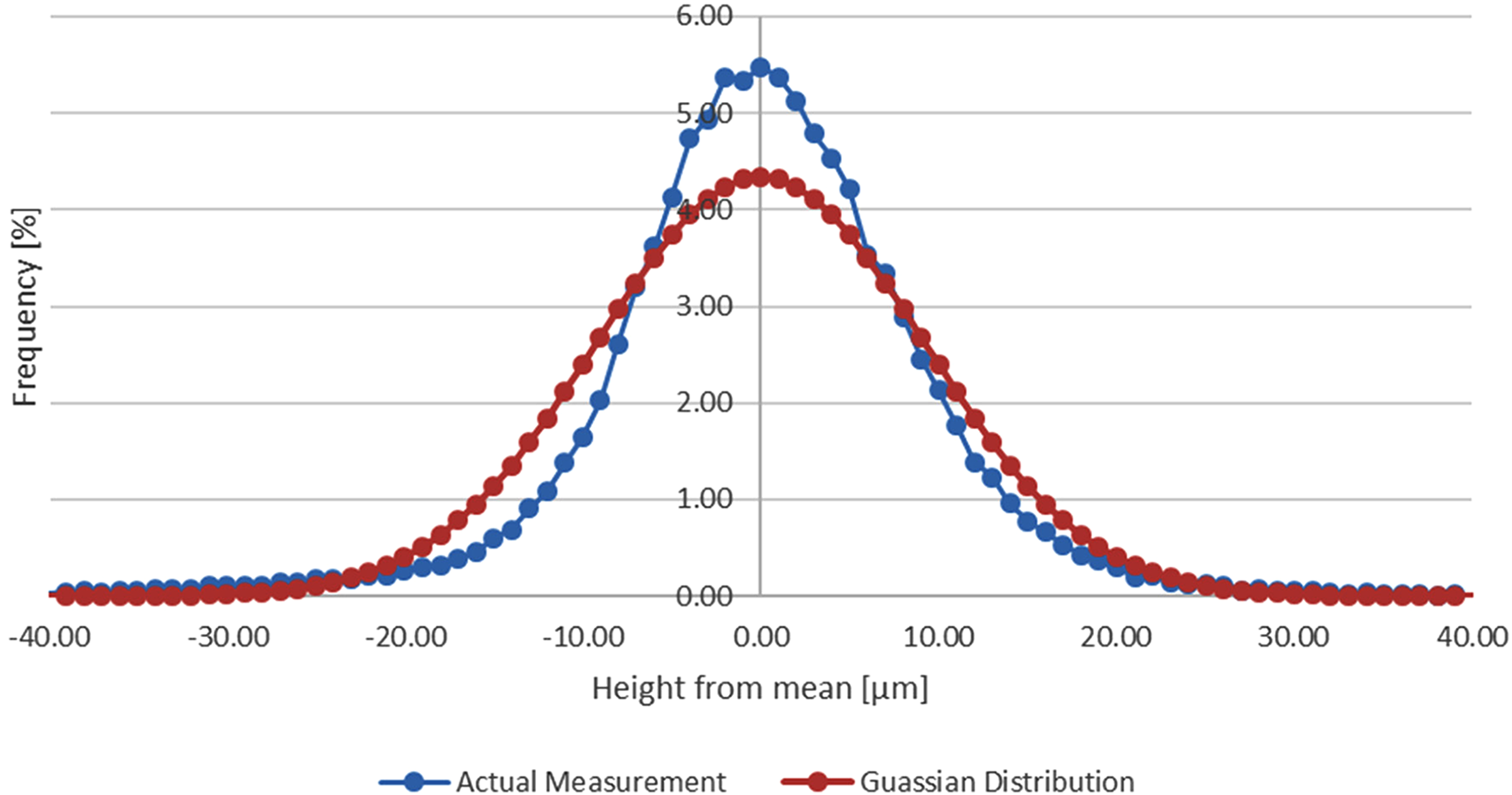
Distribution of asperity heights versus Gaussian distribution.
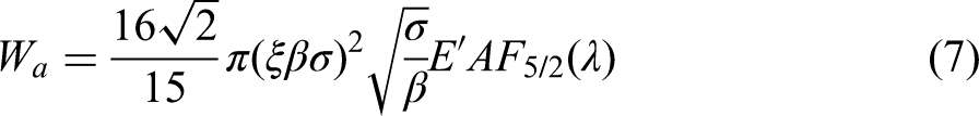
The area occupied by asperities can be obtained as follows
38
:


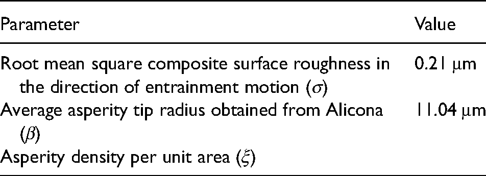
Gear surface roughness parameters.
An ultra-thin lubricant film is absorbed in the tip of asperities in contact. The thin oil film is subject to non-Newtonian shear. Therefore, the boundary friction at asperity contacts can be calculated as follows
40
:

As the result of generated heat in the contact, the temperature of teeth surfaces increases. The temperature rise at contacting tooth flank is considered as a heat source in the CFD model. The meshing of a cylindrical spur gear teeth pair yields a finite line rectangular contact of width 2b.
34
Therefore, friction per unit length is obtained as follows:
In this study, the simplified method introduced by Crook
42
is utilized. According to Crook,
42
the generated heat at gear mesh is divided equally across the gear pair, and derived the following equation to calculate the average surface temperature rise:
Computational model of impinging oil flow
A CFD model using the VOF method is used to calculate the heat transfer coefficient in different parts of the rotating gear. The CFD model was developed by Fatourehchi et al. 21 and was validated against DeWinter and Blok 12 work.
The conservation of mass and momenta governing equations for each phase in a three-dimensional (3D) Newtonian and incompressible turbulent flow are based on Hou and Zou’s 43 approach as outlined below:
Flow continuity condition:
The interface between the immiscible liquid lubricant and the liberated vapour phase is monitored using the VOF method.
47
A volume fraction function 
The CFD model equations are solved in the finite volume environment of ANSYS Fluent 16.2 software. To determine the heat transfer coefficient on different parts of a rotating gear, a 3D CFD model is developed.
21
In the developed CFD model:
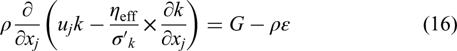
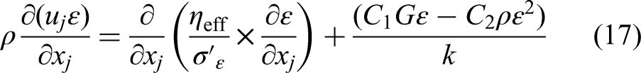
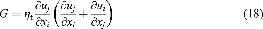
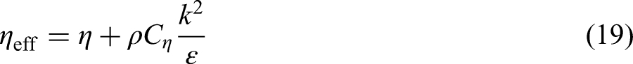
The analysis is performed based on a pressure-based VOF model. The coupled algorithm is selected to treat the velocity–pressure coupling. The fluid flow turbulence is evaluated based on the standard k–ε turbulence model.
Gears in a racing vehicle are rotating at a relatively ultra-high speed (around 11,000 r/min). To avoid the complexity of modelling a complete gear pair at such high speed, it is assumed that the effects of change in flow pattern around the contact zone induced by the mating gear pair on the gear surface heat transfer coefficient are negligible. Therefore, the CFD model is developed for a single gear. Figure 2 presents a schematic of the CFD model, demonstrating boundary conditions of different parts of the model.
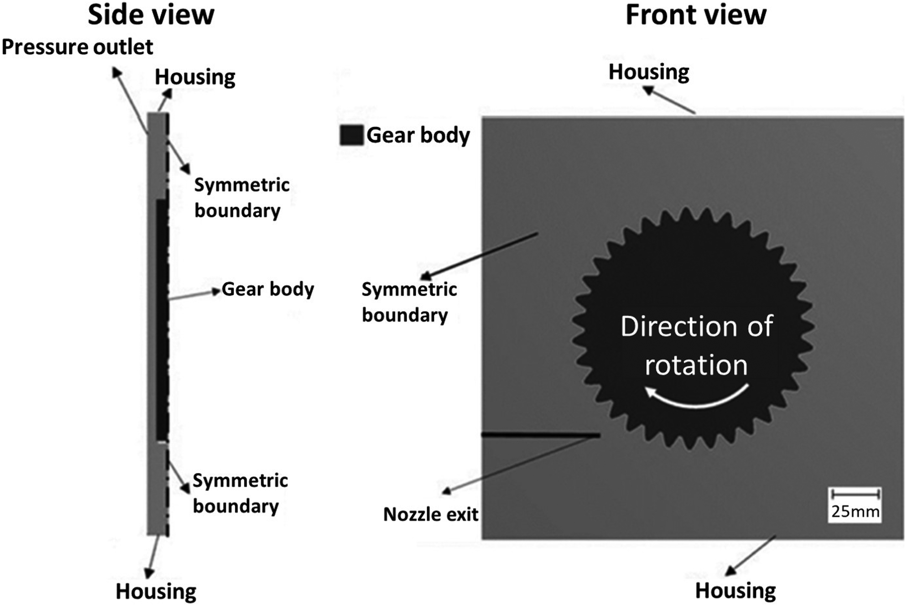
Schematic representation of the computational fluid dynamics (CFD) model.
The oil jet is directed at the out-of-mesh position to give a better cooling performance. 23 According to Figure 2, a large box is considered for the rotating gear. This is to minimise the impact of the computational boundary upon the results. The oil jet mass flow rate at the nozzle exit is 0.0168 kg/s at 100 °C. The atmospheric pressure is assumed at the outlet boundary.
Loaded gear rotates at a very high speed. Therefore, its teeth temperature drop is neglected during the time of exiting the contact and going into the contact in the next revolution in the CFD model. Based on this assumption, the average temperature rise during the gear contact is applied to all teeth in the CFD model (i.e. as the heat source). The average temperature rise is determined based on the method introduced in the previous tribology section.
The cooling oil is impinged at the rotating high-temperature gear teeth. The area-weighted average heat transfer coefficient on the rotating teeth surfaces is monitored. The CFD model is run until the rate of change of the average heat transfer coefficient steadies.
Transient thermal model of heat conduction
A finite-element method is used to evaluate heat conduction of a gear pair in a dry sump environment. In this study, the introduced transient model of one gear tooth with a single oil jet 29 is further developed. Another gear with a connecting shaft is added to the model. The gears are mounted directly to the shaft (i.e. no bearing is used). The second gear is lubricated through a separate nozzle. Only one of the gears is loaded during the entire simulation. Based on this modelling approach, the effect of having simultaneous oil jets on loaded and unloaded gear pairs on the thermal functioning of dry sump systems is investigated. Moreover, the contribution of conduction heat transfer to unloaded gears on the total heat dissipation is studied.
Every single gear tooth undergoes the same heating (i.e. meshing period) and cooling conditions at every gear revolution. Thus, the resulting temperature distribution is identical for all gear teeth. Consequently, the thermal analysis can be performed on a single tooth segment.13,20 Figure 3 shows boundary conditions of the developed finite-element model of two teeth segments and the connecting shaft.
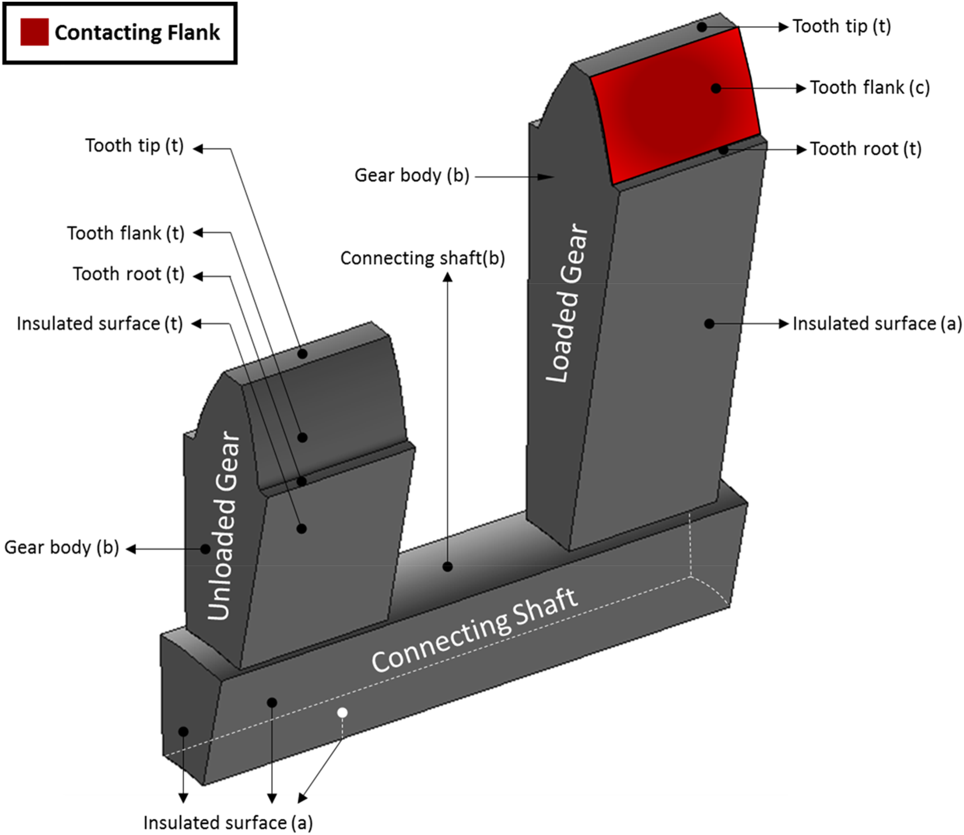
Boundary conditions of the finite-element model.
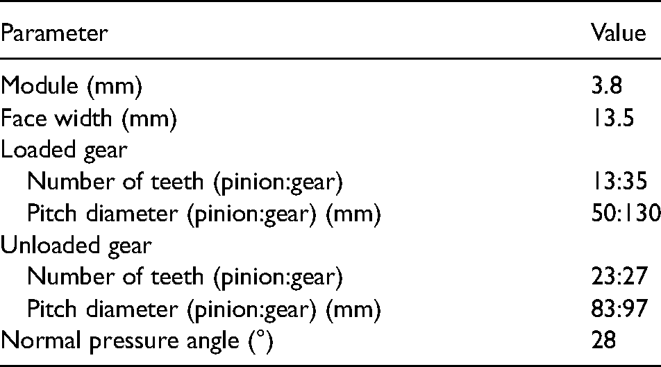
Table 3 provides the geometrical properties of the gears.
Gears geometrical properties.
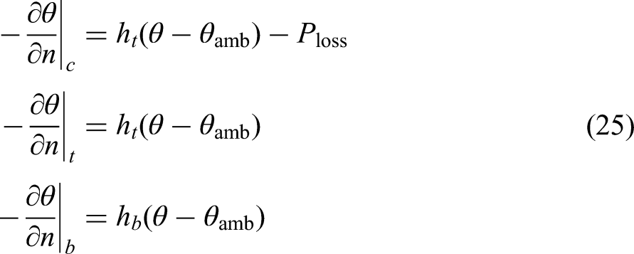
At every revolution of the gear, the generated heat due to the contact power loss is applied as heat flux to the contacting flank (Figure 3) during the meshing cycle. The temperature distribution in gears is determined based on the Fourier heat conduction equation: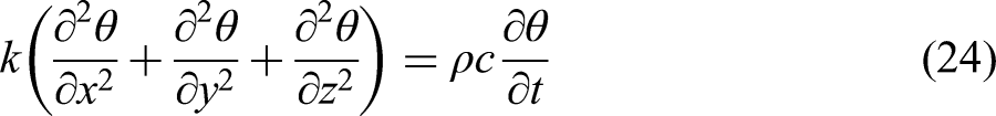
Method of solution
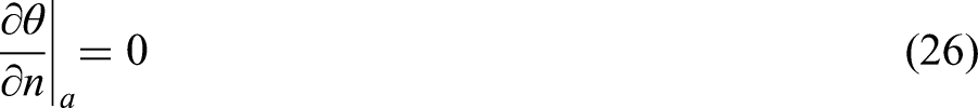
The developed integrated multi-scale and multi-physics method is run based on experimental input data. The experimental test is performed on a high-performance transmission operating under the dry sump lubrication system. The input speed and torque are altered during the test and the oil temperature is measured at the scavenging point. The test was carried out in about 400 s where the average input speed was around 11,000 r/min. This requires very fine time steps in the finite-element model to capture the meshing period at each gear revolution. A Matlab script is developed to integrate all the above-mentioned models including tribology for estimation of heat generation as well as CFD and finite-element models to estimate the heat dissipation. A flowchart of the iterative solution procedure is presented in Figure 4.
Solution procedure of tooth thermal analysis.
It should be noted that the contact power loss determination does not affect the transient temperature rise of the gear surface.
Results and discussion
The test is carried out on a transmission system comprising eight spur gear pairs with 64 individual oil jet nozzles injecting the oil on different parts of the transmission. After oil hits rotating gears teeth, it flows to the sump area of transmission housing where it is scavenged and pumped again to the oil galleries. Only one of the gears is loaded in the entire test time.
The variation of speed and torque measured from the experiment forms the input to the simulation. The variation of measured torque was 50 Nm. Therefore, the average measured torque of 500 Nm is utilized in the simulation. Simulation results are then compared with the measured oil temperature at the oil scavenging point of the transmission system. This is to compare and validate the qualitative behaviour of the simulation results against measurements. It is important to emphasise that measuring the transient surface temperature of the running gears at such high speeds (i.e. around 11,000 r/min) is not feasible.
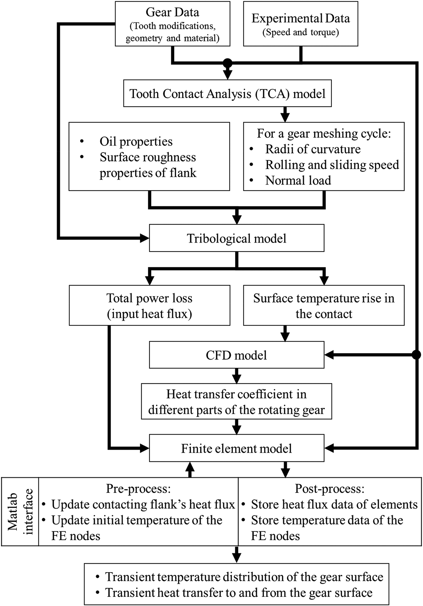
Figure 5 shows the speed variation during test time and the measured oil temperature at the scavenging point of the transmission system. An eighth degree Fourier function is fitted to the measured data to eliminate the measurement noise.
Variation of the input speed to the transmission system and the oil out measured temperature at the scavenging point.
The thermal analysis is performed using the integrated multi-physics model. Both the system model (multiple gears) and the component model (single gear as reported by Fatourehchi et al. 29 ) are conducted. This is to investigate the effect of multiple oil jets on the convection heat dissipation rate. Moreover, the effect of an adjacent unloaded gear on conduction heat transfer is studied. Figure 6 illustrates temperature distribution on selected points I–IV on the cycle, which are shown in Figure 5.
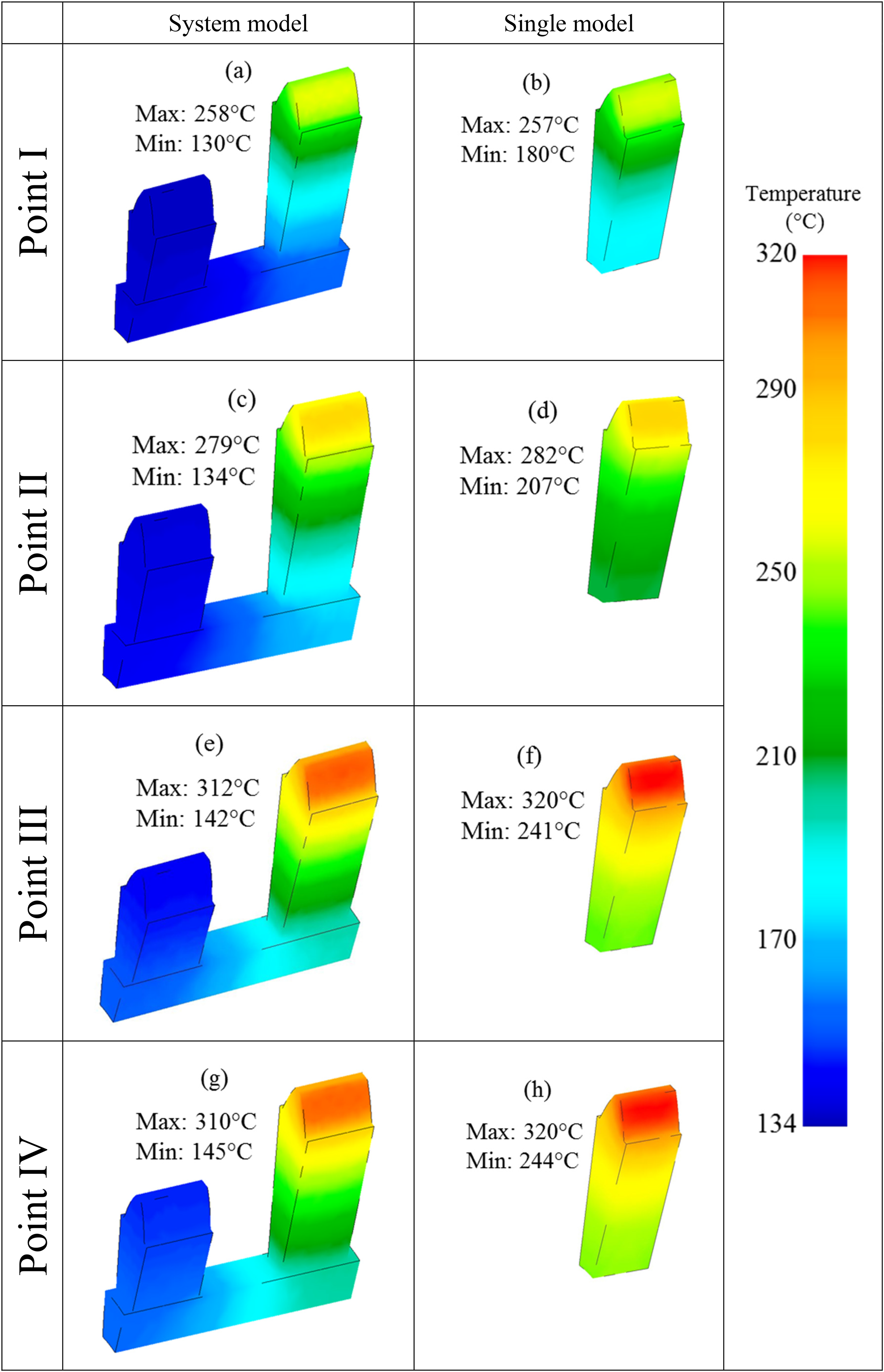
Temperature distribution on selected points along the test cycle.
According to Figure 6, the loaded gear in the system model has a similar temperature distribution with a single model at the beginning of the cycle (Figure 6(a) vs. Figure 6(b)). However, as time passes heat flow to the unloaded gear increases (Figure 7). Therefore, the loaded gear in the system model has a relatively lower temperature compared with the gear in a single model. The estimated maximum temperature of the loaded gear in the system model is about 10 °C lower than the single model (point IV; Figure 6(g) vs. Figure 6(h)) approaching the end of the test cycle. Deducting the amount of convection heat transfer to ambient, Figure 7 depicts contours of heat flux at the beginning and end of the test cycle. The maximum heat flux in the colour bar is limited to 200 mW/mm2. Thus, the variation of heat flux becomes more visible.
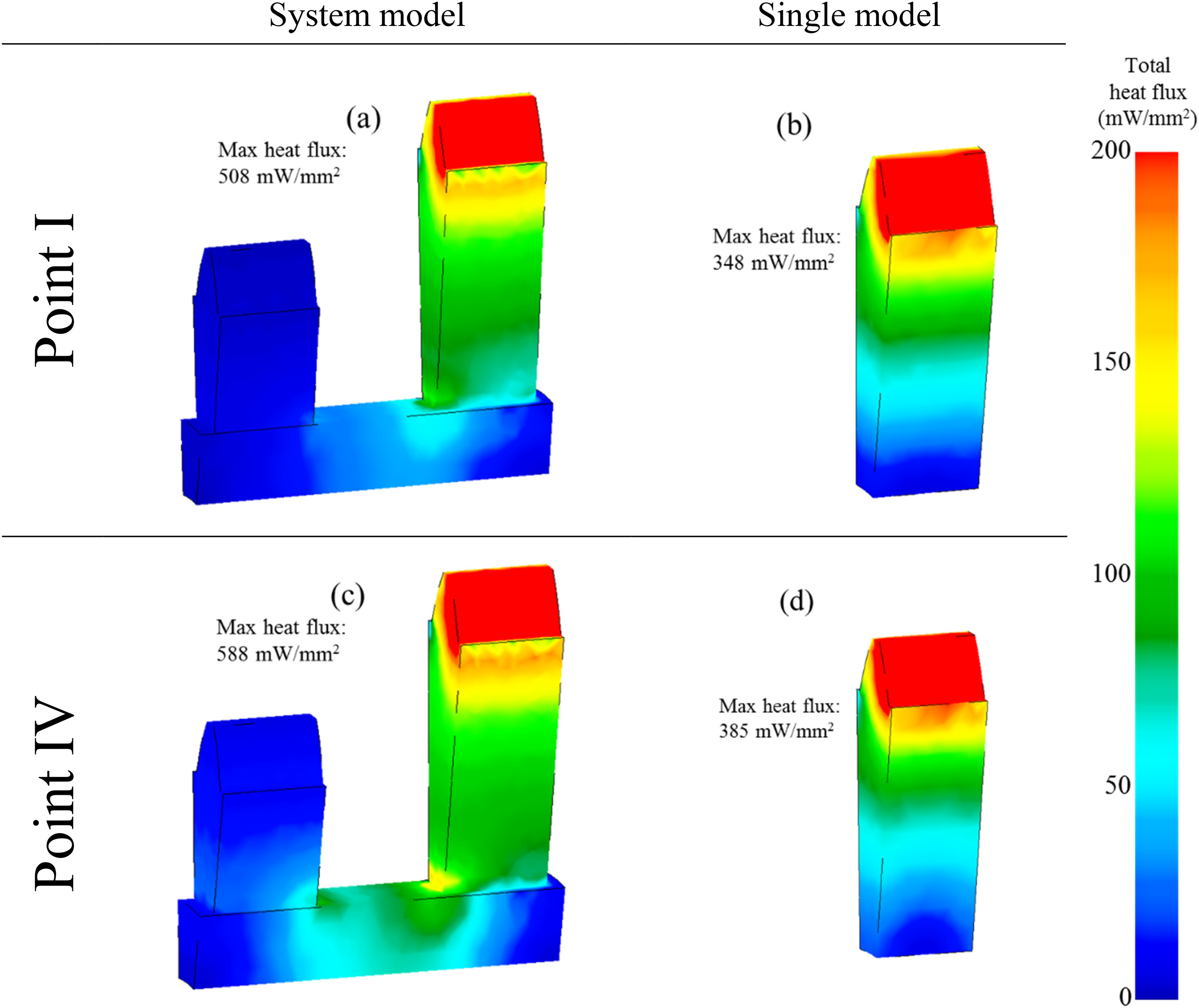
Contours of total heat flux at the beginning and end of the test cycle.
According to Figure 7, the highest heat flux is associated with the contacting flank where the generated heat in contact flows to the body of the gears. It should be noted that there is no heat generation mechanism in the unloaded gear in the system model. Therefore, heat transfer within the unloaded gear and its temperature variation remain low. The low temperature of unloaded gear in the system model causes a higher temperature gradient and consequently, a higher heat flux happens in the system model. However, the higher temperature in a single model results in a higher rate of convection heat transfer to the ambient. This is shown in Figures 8 and 9 as convection heat flux and the absolute amount of convection to ambient, respectively.
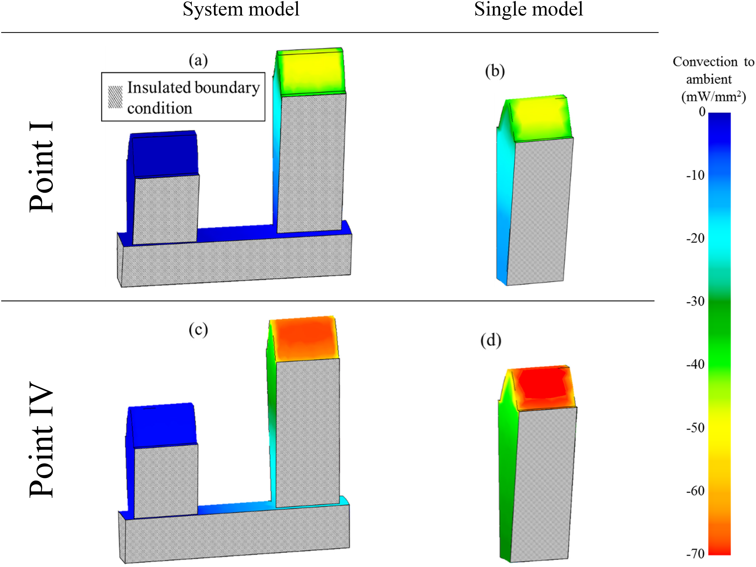
Contours of convection heat flux to ambient at the beginning and end of the test cycle.
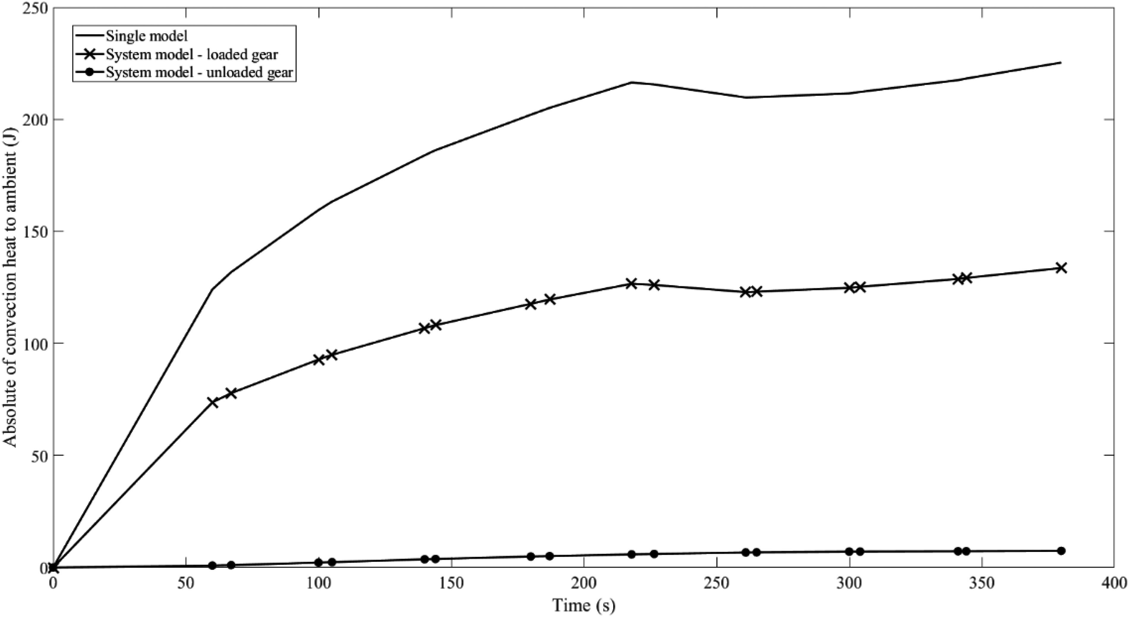
Absolute amount of convection to ambient along the test cycle.
Due to the low-temperature change of the unloaded gear in the system model, its temperature difference with ambient remains low. Therefore, heat convection through the unloaded gear in the system model is significantly lower during the entire test cycle (Figures 7(a), (c) and 8). This fact can potentially help to optimise dry sump transmission systems. For instance, low gears are not engaged during an entire racing lap. 23 Hence, oil jet flows on those can be minimised to improve the overall efficiency of the system.
Figure 10 shows a qualitative comparison between the simulation results and those measured in the test rig. The lubricant temperature measured at the outlet of the gearbox under variable load and speed and is shown in Figure 5. In Figure 10, the corresponding temperature values of measurement data are shown on the right-hand side vertical axis, and temperature values of simulation results are shown with respect to the left-hand side vertical axis. The simulated flank temperature is the operating gear surface temperatures, while the measured data are for the oil temperature at the outlet of the gearbox. Results show that the trend of temperature rise in simulation closely follows the one from the experiment. The heat is convected from the gear surface to the lubricant. However, due to the high-speed gear operation, the lubricant leaves the domain with a small increase in its temperature. 21 Before reaching the scavenging point of the gearbox, the heated lubricant is cooled down through convection heat transfer with low temperature impinging oil jet in the gearbox casing (up to 64 jets). Therefore, as is shown in Figure 10, the measured oil temperature at the gearbox outlet is lower than that predicted for the contacting flank temperature.
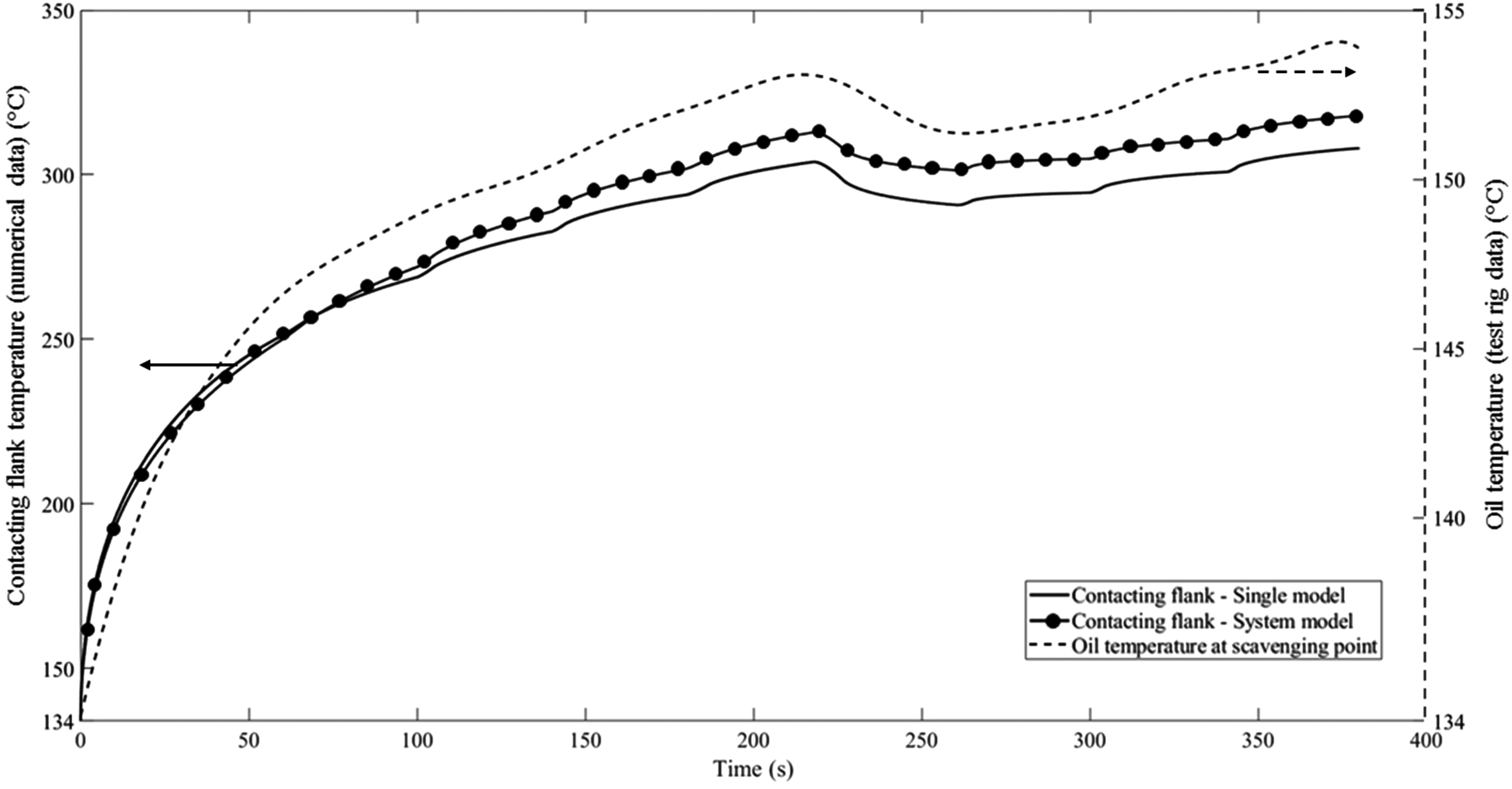
Qualitative validation of the analysis results against measurement.
Figure 11 compares the contacting flank temperature with the average tooth temperature in both single gear and system models. The tooth temperature in Figure 11 corresponds to the average temperature of all finite-element nodes of the tooth at all time steps. The generated contact heat first reaches the meshing flank temperature. Therefore, in Figure 11, the variation in frictional heat generation as a result of changes in the operational conditions is more sensitive to the meshing flank. The average temperature of the tooth segment, on the other hand, increases gradually as the conduction heat transfer through the gear body takes more time. Moreover, the temperature difference between contacting flank and the tooth is higher in the system model. This is due to the higher rate of heat dissipation through conduction to the unloaded gear.

Comparison of contacting flank temperature with the average tooth temperature.
Conclusions
In this paper, an integrated multi-physics and multi-scale numerical method of a dry sump transmission is presented. The method incorporates a component level tribological heat generation model and a CFD heat convection model into a system-level transient thermal finite-element model of solid boundaries. The proposed model is capable of simulating the transient behaviour of high-performance transmission systems for a wide range of operational conditions. This approach enables the determination of the quantity of generated heat in lubricated gear pair contacts, as well as the transient heat transfer and temperature distribution within multiple gears. Thus, the thermal functionality of a dry sump transmission can be optimized.
The following conclusions are drawn:
Qualitative validation of results shows a very good agreement between simulation results and measurements data. The temperature of the unloaded gear remains low. This causes a higher temperature gradient in the system model compared with the single gear model. Consequently, higher heat flux from the contacting flank (heat generation boundary) to the rest of the system is observed in the system model. The unloaded gear temperature difference with ambient is low. Therefore, the convection heat dissipation rate from the unloaded gear remains low. As a result, the oil jet flow rate on the unloaded gear does not necessarily require to be equal to the oil jet flow rate on the loaded gear pair. The integrated model provides a prediction tool for design optimization of dry sump lubrication systems by ensuring the availability of sufficient, but not excessive oil flow rates through oil jet nozzles on loaded and unloaded gear pairs. The methodology can be used over a driving cycle with a variable load and speed, in which the amount of generated heat in contact and consequently the temperature gradient at contacting flank will change according to the variable conditions. The provided methodology in this paper strived to present the concept of multi-physics thermal modelling for a jet lubricated geared system which can be efficiently performed. Hence, a small system comprising two gear pairs is considered. This methodology can be further expanded to a bigger system with more gear pairs and higher complexity. The presented methodology is provided for specific spur gears. However, it is applicable for other types of gears such as helical and other applications such as high-speed electric drives. However, TCA, CFD and finite-element models should be modified based on the appropriate gear geometry.
Footnotes
Acknowledgement
The authors thank the ANSOL company for supplying the CALYX software, which was utilized for TCA analysis in this study.
Declaration of Conflicting Interests
The authors declared no potential conflicts of interest with respect to the research, authorship and/or publication of this article.
Funding
The authors received no financial support for the research, authorship and/or publication of this article.