
Abstract
In this work, a finite element-based model is presented that simulates elastohydrodynamic lubrication in coated finite line contacts. Using this model, the film thickness and pressure distributions, between a straight roller with rounded edges on a plate, were analyzed. The model was successfully validated against representative results reported in literature. Parameter studies were conducted to study the influence of varying operating conditions, axial surface profile parameters and coating mechanical properties on the overall elastohydrodynamic lubrication behavior of the contact. It was found that in contrast with typical elastohydrodynamic lubrication behavior, the maximum pressure and minimum film thickness, which are located at the rear of the contact, are largely influenced by variations in load. Results also reveal that axial surface profile parameters and coating mechanical properties may act as amplifiers to the effect of load on pressure and film thickness distribution and can thus, if smartly chosen, significantly enhance lubrication performance.
Introduction
From past literature, dedicated to elastohydrodynamic lubrication (EHL), one may retrieve that a lot of work has been done on elliptical point and infinite line contact problems. In the latter, a uniform pressure distribution in axial direction is assumed. However, significantly less work has been done on finite line contact problems despite the high importance of the topic. Due to the finite lengths of components, high stresses are generated towards the extremities of the contact, often referred as edge loading. Typical examples include cam-roller followers pairs, rolling element bearings, gear teeth, etc. Axial surface profiling of components is therefore often utilized to minimize edge loading.
Depending on the type of surface profiling, the pressure and film thickness distribution may deviate significantly from that predicted using the infinitely long line contact assumption. The foundation of these observations was laid by experiments performed in 1967–1974 by Gohar and Cameron 1 and Wymer and Cameron. 2 In the latter, they measured the film thickness distribution for tapered rollers on a glass plate using optical interferometry. They were able to show that film shapes near the ends were very different from those at the central plane. Moreover, the absolute minimum film thickness always occurred near the extremities of the roller. The minimum film thickness and maximum pressure are crucial design parameters as they significantly affect wear and fatigue and thus ultimately the service life of the component.
Mostofi and Gohar 3 were one of the first to present a numerical solution to the finite line contact EHL problem. The type of rollers used was those with a straight length and rounded edges. However, the numerical results near the position were profiling starts were physically inconsistent. Using the same profiled rollers as in Mostofi and Gohar, 3 Park and Kim 4 obtained improved contour plots for the pressure and film thickness distribution using an improved numerical scheme as described in Park and Kim. 5 They also concluded that the maximum pressure and minimum film thickness always occur near the position were the profiling starts. The aforementioned numerical studies were rather limited to low or moderate loads. Extension to higher loads was made by Kushuwaha et al. 6
Shirzadegan et al. 7 recently presented a finite element-based model applicable to finite line contacts. The model developed by Shirzadegan et al. 7 is an extension of the pioneering work of Habchi et al. 8 and can easily cope with highly loaded situations by means of numerical stabilization. In Shirzadegan et al. 7 , different types of axial profiling were considered, i.e. rounded edges, logarithmic and crowing, and their influence on lubricant performance.
The aforementioned studies serve sufficient knowledge to perform more in-depth investigations in order to gain a fundamental understanding into the design limits of finite line contact problems. In most practical engineering applications operating conditions, such as entrainment velocity, radii of curvature and load vary with time. It is therefore important that the axial surface profile shape should suffice over the full range of operating conditions. Moreover, nowadays an increasing trend in the use of surface coatings in lubricated contacts is observed, and from past studies,9–12 one may conclude that smart use of surface coatings can significantly enhance lubrication performance. However, according to the authors’ knowledge past studies, concerning lubricated-coated contacts, are rather limited to infinite line contacts and circular contacts.
Therefore, this paper presents a finite element method (FEM)-based finite line contact model that includes the possibility of having a coating on interacting solids. In this work, the lubricated conjunction of an axially surface profiled roller on a plate is analyzed. The numerical predictions are first quantitatively validated with benchmark results found in literature. Furthermore, the influence of operating conditions, roller profiling and coating mechanical properties on the tribological behavior of the contact is investigated.
Mathematical model
The model presented herein is similar to the circular coated contact model presented by Habchi, 12 but then slightly modified in order to simulate finite line contacts. Furthermore, isothermal conditions are assumed to simplify the analysis. The model relies on a full system finite element resolution of the EHL governing equations, which are the Reynolds, linear elasticity and the load balance equations.
The equivalent computational domain Ω, for the EHL problem, is presented in Figure 1 where above the substrate a coating is present with a unit dimensionless thickness. Furthermore, both coating and substrate share a dimensionless axial length of two. The aforementioned geometrical dimensions, for both coating and substrate, are irrespective of the actual coating thickness Equivalent geometry for EHL analysis of the finite line coated contact problem. Note that the dimensions are exaggerated for the sake of clarity.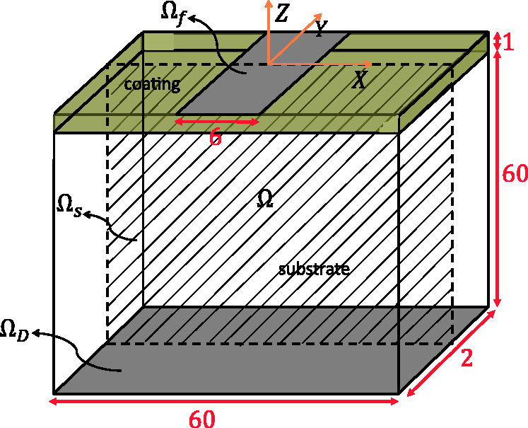
The Reynolds equation, which is a convection-diffusion type equation, is strongly convection dominated in highly loaded situations and will thus exhibit superious oscillations in the solution when solved using a typical Galerkin formulation. 13
The inconsistent (non-residual based) artificial diffusion method is one of the oldest and simplest methods as it directly adds an artificial diffusion term to the Reynolds equation in regions where the solution is strongly convection dominated. In Habchi et al.,
8
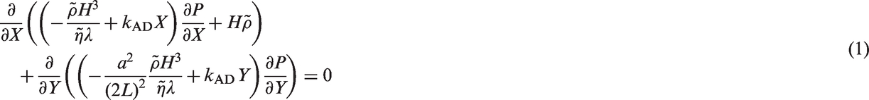
it was shown that the solution was not significantly affected with the use of isotropic artificial diffusion. Hence, in this work the inconsistent artificial diffusion stabilization technique is used. The slightly modified Reynolds equation can now be written as follows
The free boundary cavitation problem that arises at the exit of the lubricated contact is treated according to the penalty formulation of Wu.
16
This method adds an additional (penalty) term to the Reynolds equation that only acts in the negative pressure zones. The penalty term enforces the arising negative pressure in the solution towards zero. It is important to note that the equivalent diffusion tensor


As can be extracted from equation (2), the only difference between the definitions of
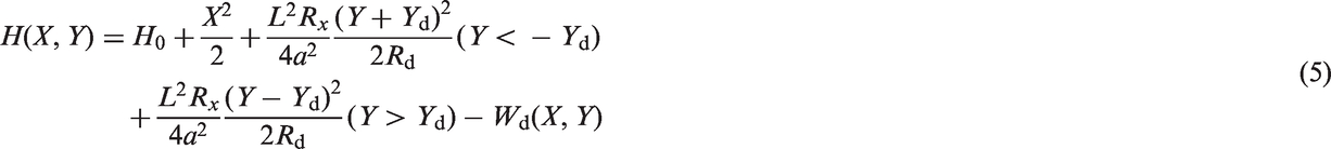
The EHL film thickness expression H for a straight cylindrical roller with axial dub-off profiling (see Figure 2) can simply be written as Park and Kim
4
Schematic of considered roller axial profile.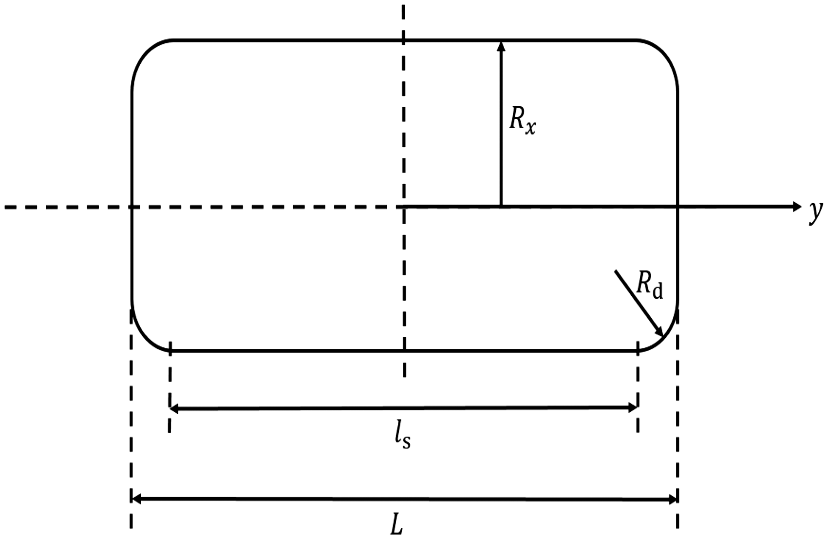
The conservation law states that the applied load should be balanced by the hydrodynamically generated force. Assuming that acceleration forces are negligible, the following load equation should hold for the contact

Note that equation (6) already takes into account symmetrical boundary conditions at plane
For the elasticity problem three assumptions are made, namely:
both substrates are coated the substrates of both interacting bodies share similar mechanical properties, i.e. the coating materials on both substrates also share similar mechanical properties, i.e. i.e.
where subscripts “s” and “c” denote substrate and coating, respectively. Note that the aforementioned assumptions are purely made here to simplify the analysis. Extension to other problems, such as usage of different coating and/or substrate materials, can straightforwardly be taken in to account.
For the elastic deformation calculation, we again make use of an equivalent elastic model, see Habchi et al.
8
for more details. In the equivalent elastic model, one of the interacting bodies, thus substrate with coating, is rigid while the other body has equivalent material properties to compensate for the total elastic deformation. As both substrates and coatings share similar mechanical properties, the equivalent dimensionless material properties for substrate (


In the current case, since the two substrates and coatings are made of the same material it means that the use of the equivalent material properties defined in equation (7) leads to a total elastic deflection that is twice that of each solid body (substrate + coating) taken individually.
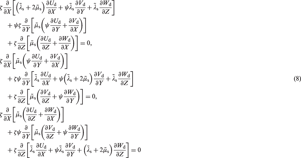
In fact, now two interdependent sets of the system of 3D elasticity equations need to be solved to calculate the elastic displacement field in both coating and substrate. The 3D elasticity equations are applied to dimensionless domain Ω to compute the total elastic deformation. The sets of equations described by eqns.8 and 9 describe the elastic deformation of substrate and coating, respectively. For the substrate we get
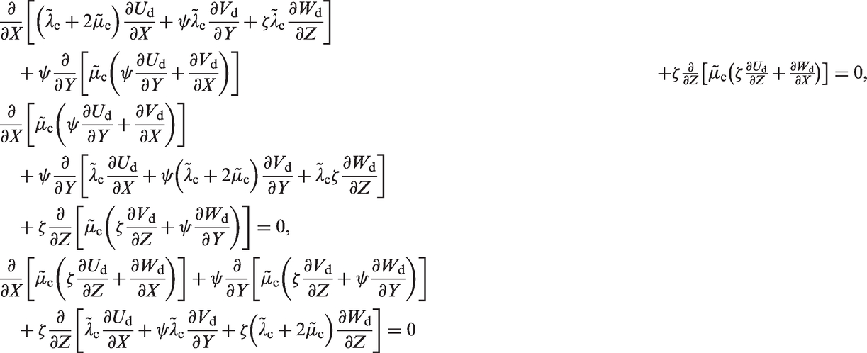
And for the coating


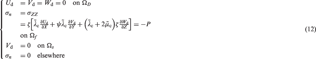
In order to obtain a unique solution for the EHL problem, proper boundary conditions (BCs) need to be imposed. These are summarized as follows:
For the Reynolds equation

For the elastic model
Additionally, a continuity BC on the common boundary of coating and substrate is imposed.
Results
Summarizing, the complete model consists of the modified Reynolds equation (1), the load balance equation (6), two sets of interdependent elasticity equations for substrate and coating equations (8) and (9), and their respective boundary conditions equations (11) and (12).
The dry dimensionless Hertzian pressure profile was taken as initial guess for the pressure distribution, while for the elastic displacement field the solution corresponding to the dry Hertzian contact was taken as initial guess. The load balance equation (6), which is associated with the unknown H0, is added to the complete system of equations formed by equations (1), (8) and (9).
The developed model is solved using the FEM with a general purpose finite element analysis software.
18
The resulting system of non-linear equations is solved using a monolithic approach where all the dependent variables
Lagrange quintic elements were used for the hydrodynamic part, while quadratic elements were used for the elastic part. A custom-tailored mesh, similar to that detailed in Habchi,
12
was deployed to reach an optimum combination between accuracy and calculation speed. The maximum element size in the contact zone in X-direction was chosen smaller than 0.06 while for Y-direction the maximum element size was chosen to be smaller than 0.03. This is because steeper gradients are expected in Y-direction. The element size was allowed to increase gradually as the distance from the contact boundary increased. The aforementioned corresponds to the usage of approximately 350,000 degrees of freedom for the uncoated case and approximately 400,000 degrees of freedom for the coated case. Converged solutions to relative errors ranging between
The results herein are presented in twofold. The first part of the results corresponds to uncoated contacts, while the second part discusses results corresponding to coated contacts. Note that the particular case when the Young’s moduli of coating and substrate are identical, i.e.
Uncoated case
Influence of numerical stabilization on overall solution
The tuning factors
It is widely known, for infinite line and point contacts, that with increasing loads the Petrusevich pressure spike(s) shift more towards the exit of the lubricated contact and becomes smaller in magnitude at the same time. The maximum pressure then occurs at the center of the contact and is approximately the same as the maximum dry Hertzian contact pressure
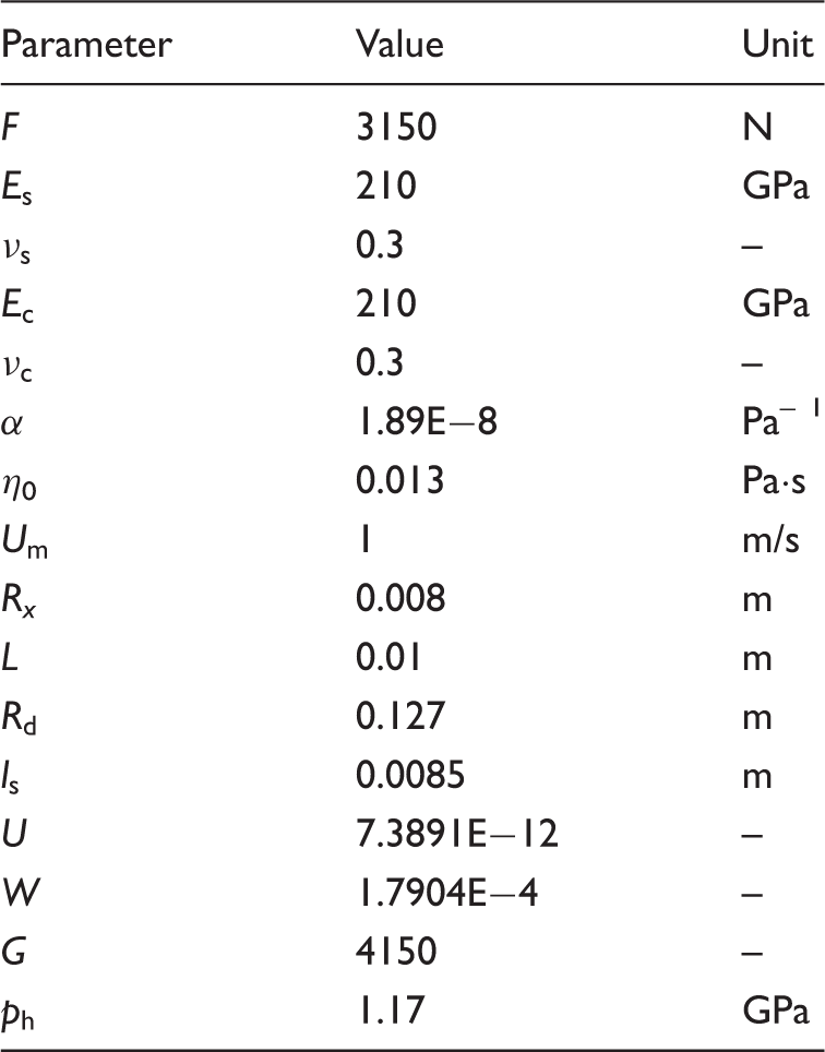
Figure 3 shows the pressure distribution for a straight roller with rounded edges with and without stabilization. The operating conditions and roller profiling geometrical parameters are given in Table 1. Note that the Young’s moduli of coating and substrate are identical, i.e. Height expressions for the pressure distribution (a) with crosswind stabilization and (b) without crosswind stabilization. Reference operating conditions and geometrical parameters for a straight roller with rounded edges.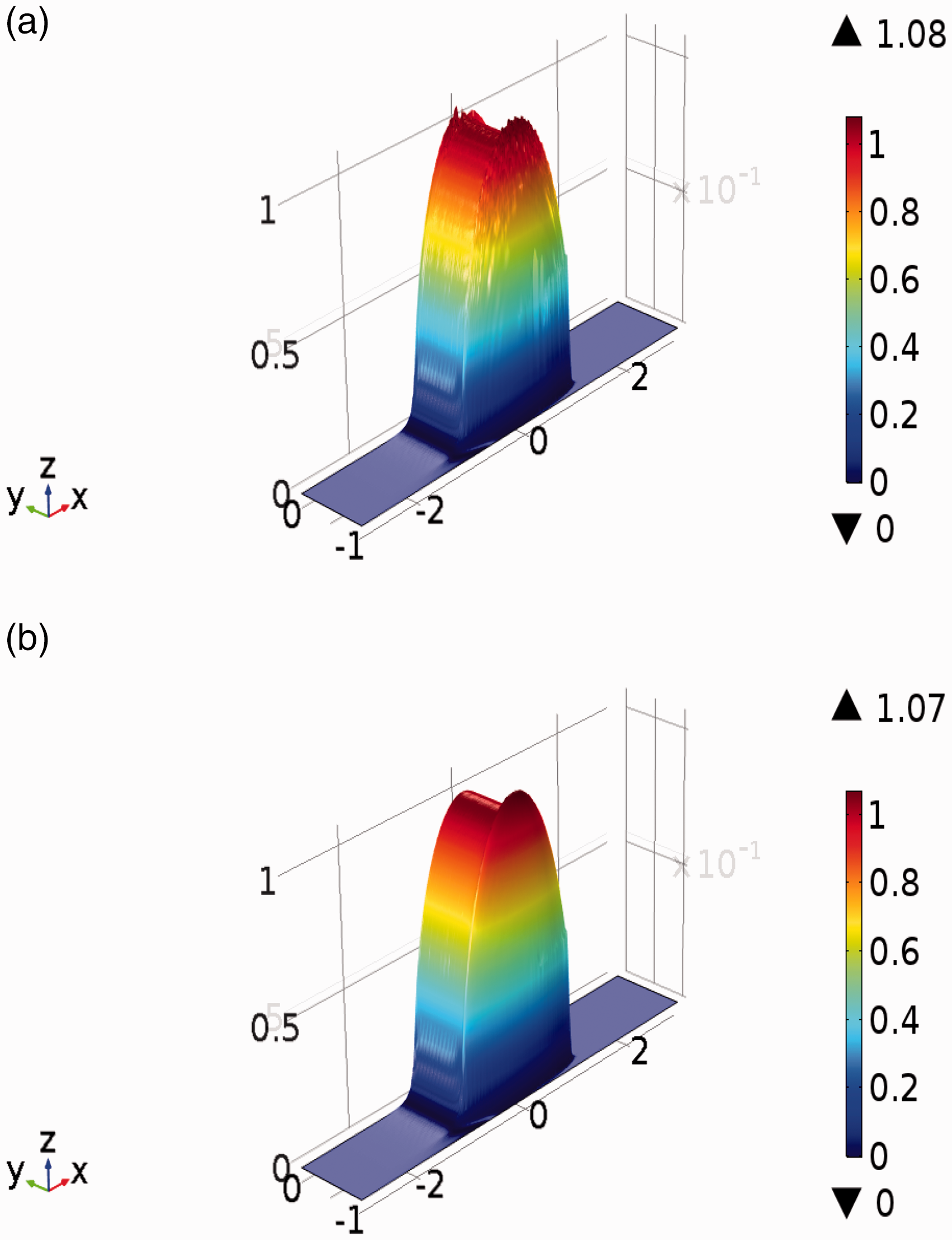
From “numerical experiments” we ascertained that the influence of crosswind artificial diffusion on the absolute minimum film thickness is much more amplified when compared to the influence of streamline artificial diffusion. This is mainly due to the fact that axial pressure gradients Influence of crosswind stabilization on (a) minima film thicknesses and (b) on axial pressure and film thickness distributions and (c) maxima pressures.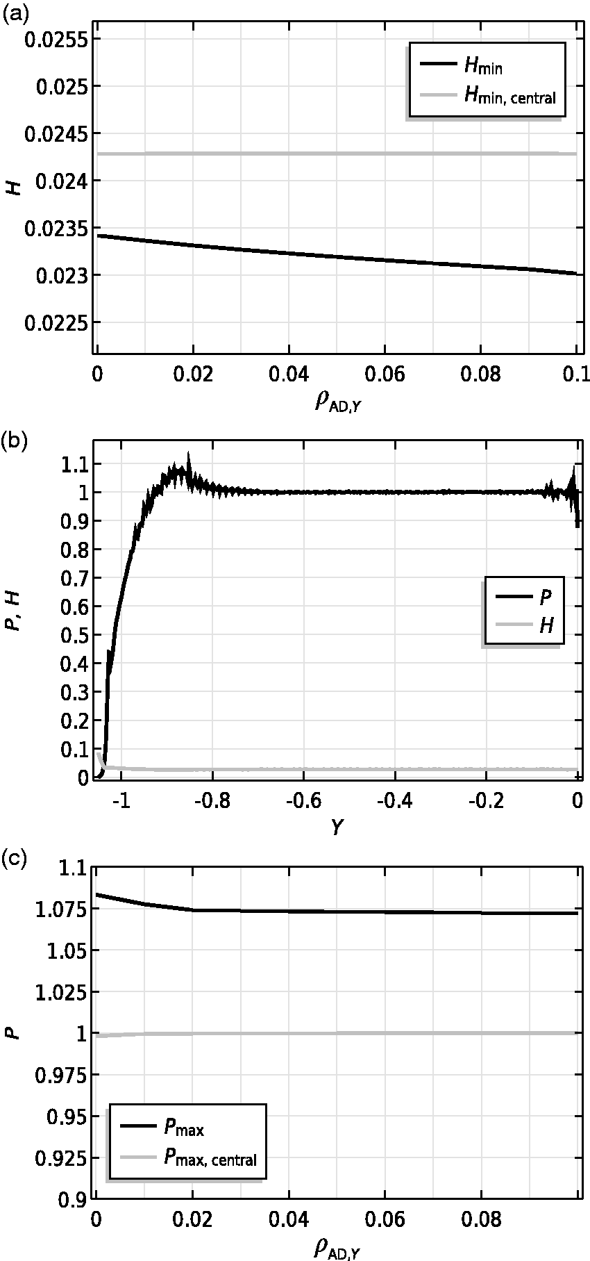
The present authors also attempted to implement more consistent (residual based) stabilizing methods, such as described in Codina 19 and Do Carmo and Galeão, 20 to stabilize the solution in crosswind direction. These include shock-capturing techniques which aim to eliminate effects such as overshoots and undershoots close to discontinuities. Unfortunately, these techniques make the system of equations more non-linear and consequently induce convergence issues. This is of course an incentive for more detailed investigation into the implementation of more consistent techniques for the “anisotropic convection-dominated convection diffusion problem.”
Quantitative validation
Operating conditions for reference case. Partly adapted from Park and Kim. 4
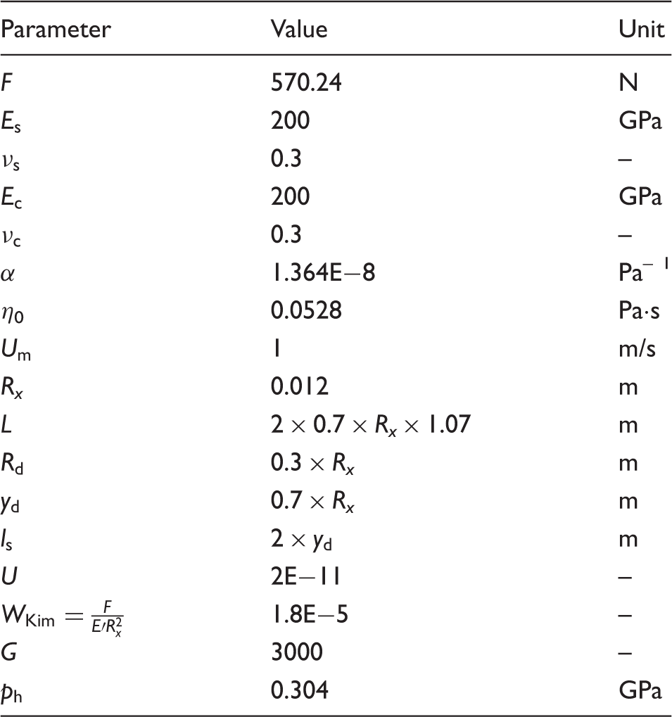
Note that the presented coated finite line contact model herein can be numerically validated with the results presented in Park and Kim 4 if the material properties of coating and substrate are set to be the same (see Table 2).
In Park and Kim
4
a slightly different definition for the load parameter (
Comparisons are made according to different sections of the contact. These correspond to the streamline and axial sections through the maximum pressure and absolute minimum film thickness. The sections are defined as shown in Figure 5.
Definition of sections through lubricated contact. Reproduced from reference Park and Kim.
4
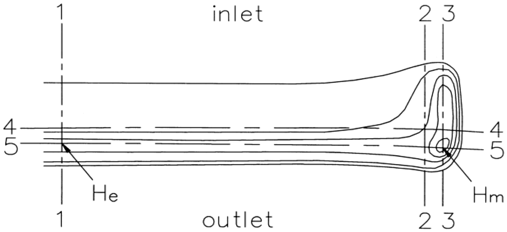
Section 1-1 is the central line in streamline direction (plotted against Y = 0) where the minimum film thickness
Figure 6 presents the zoomed-in contour plots for pressure and film thickness. Note that different dimensionless variables are used for the sake of comparison. It is clear that the maximum pressure and minimum film thickness occur near the region where profiling starts (thus near a dimensionless position of Zoomed-in contour plots of (a) the film thickness and (b) pressure distribution at the rear of the contact. Note that different dimensionless variables have been used for the sake of comparison.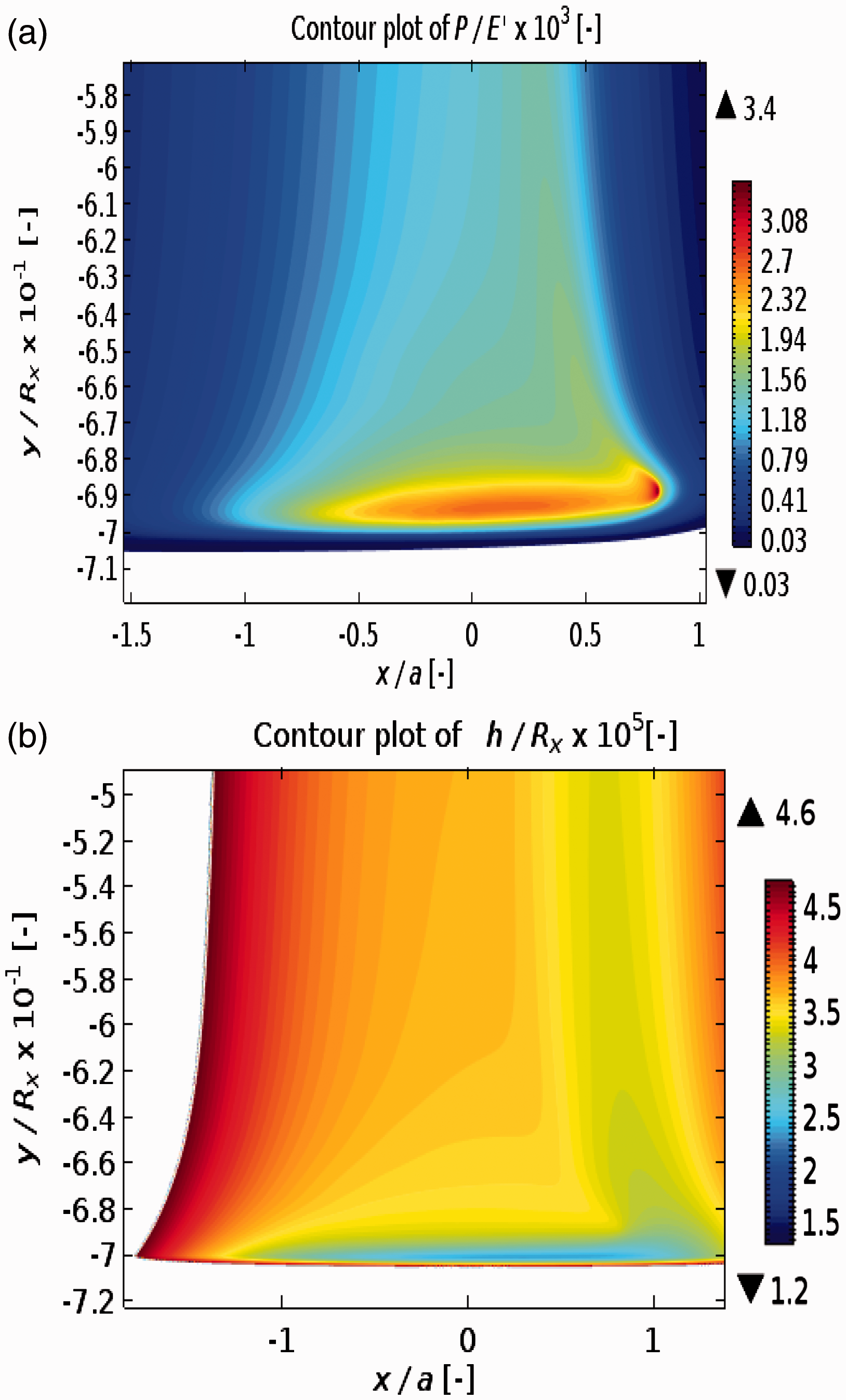
It can readily be concluded from the figures that traditional EHL infinite line contact solutions do not reveal the tribological behavior at the extremities of the contact in terms of pressure and film thickness distributions. These findings are in line with previous studies.4,6,23
In Figure 7, the results for pressure and film thickness distributions are presented according to the defined sections in Figure 5. The results are to be compared with those reported in Park and Kim.
4
Overall, good agreement is obtained for the results obtained using the current approach. The minimum film thickness and maximum pressure and their positions are accurately predicted. In Figure 7(e), there is some minor difference in obtained axial pressure distribution for Section 4-4, although the maximum pressure is accurately predicted. This is mainly due to the assumed axial length as earlier discussed. The assumed axial length might shift the location of maximum pressure a little, which in turn may lead to this discrepancy.
Results for pressure and film thickness profiles, for the different sections, using the current approach (left column). Note that here 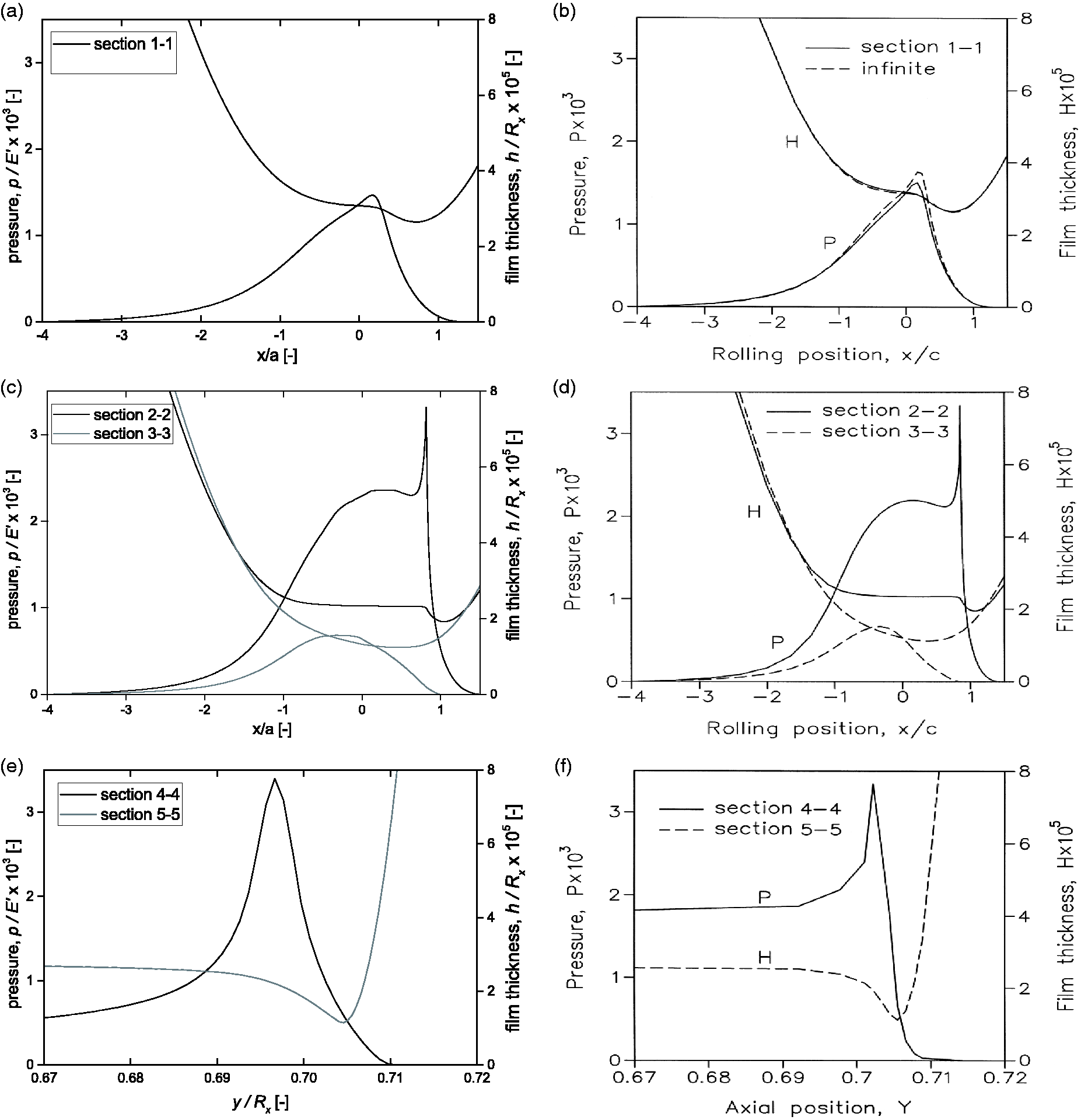
Parameter study
It is of interest to see how the finite line contact responds to varying operating conditions such as load, speed and material properties. The dimensionless parameters of the aforementioned operating conditions are represented by the load parameter W, speed parameter U and material property parameter G. The operating conditions for the current cases are detailed in Table 1.
Figure 8 shows how the pressure and film thickness distribution (plotted along X = 0 and Y = 0) vary as a function of these three parameters, while keeping two constant at a time. Variation of W, U and G all result to some minor variation around the pressure spike along the central plane and/or central film thickness variation. These variations are much more explainable from traditional EHL solutions for line and/or elliptical contacts. The most remarkable observation is that the pressure and film thickness distribution, especially at the side extremities, are highly affected by varying loads. To be more specific, the variation in pressure distribution at the extremities seems to be highly amplified with increasing load in the sense that the secondary pressure peak smears out and the covered (lubricated) axial length becomes larger. These results are in line with previous theoretical
21
and experimental findings.
4
Influence of varying operating conditions such as speed, elasticity and contact load on streamline and axial pressure shapes.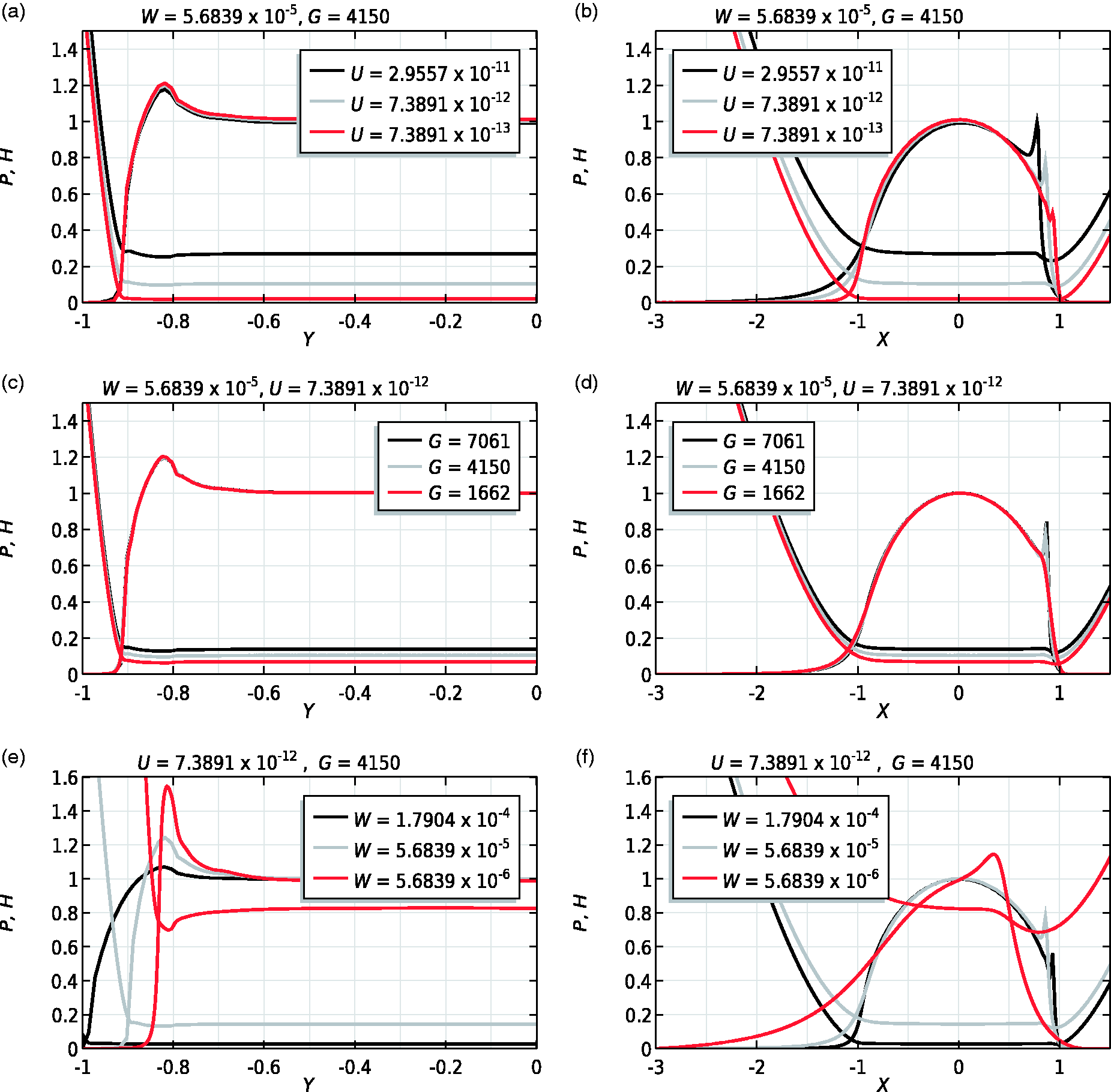
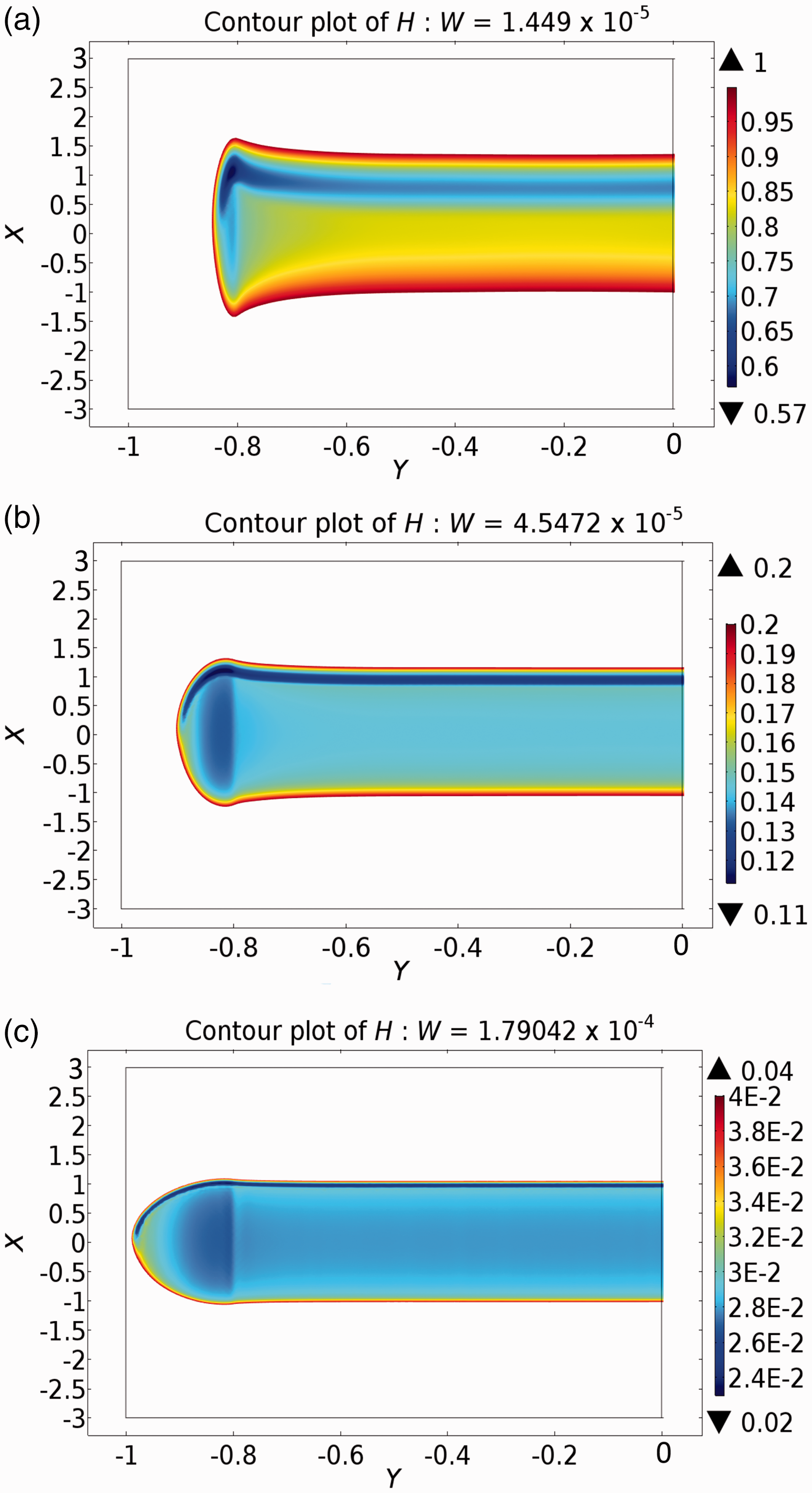
To make things more clear, Figure 9 plots the variation Variation of Contour plots of film thickness H for increasing values of dimensionless load parameter W showing how the position of minimum film thickness shifts as the contact center flattens.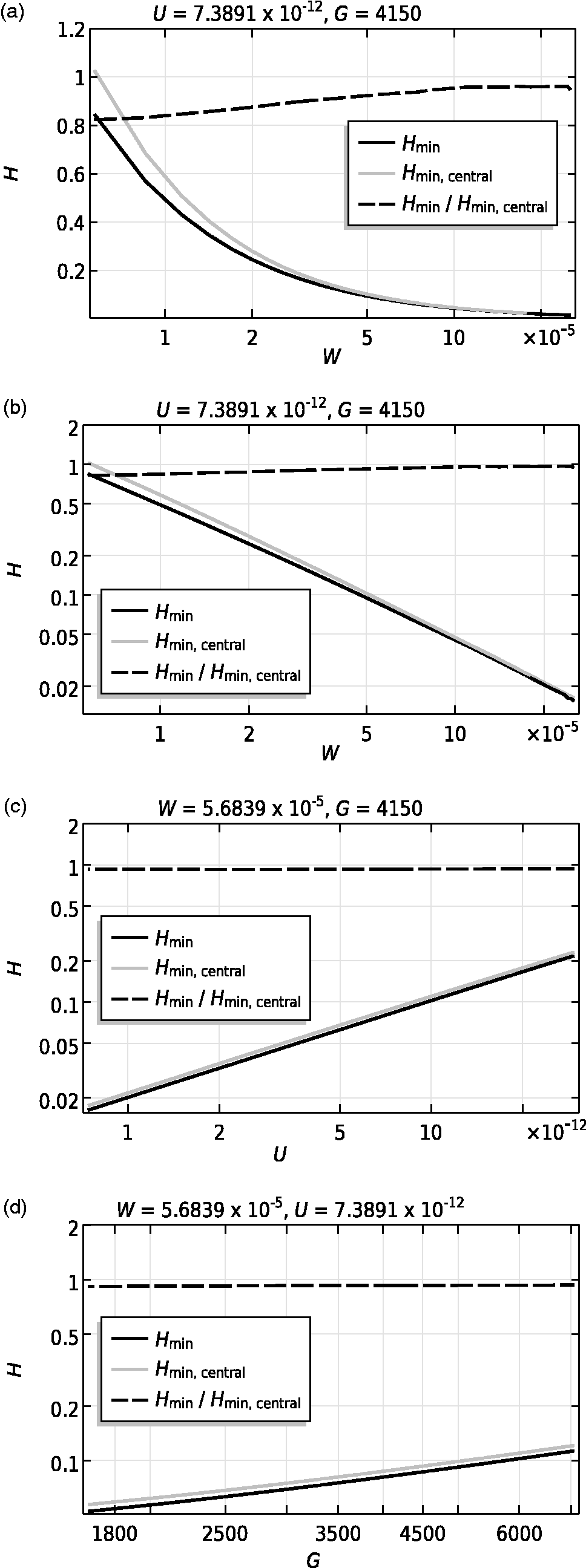
So, apart from varying operating conditions, it is also interesting to take a look at the influence of geometrical parameters on the pressure and film thickness distributions. In fact, for the axial profile of the roller one may vary the straight roller length and dub-off radius to optimize the pressure distribution, i.e. to make it more uniform by reducing edge stress concentrations and consequently increase
Figure 11 presents the variations of pressure and film thickness profiles as a function of the dub-off radius Influence of round corner radius on (a) pressure and film thickness distributions and (b) minima film thicknesses.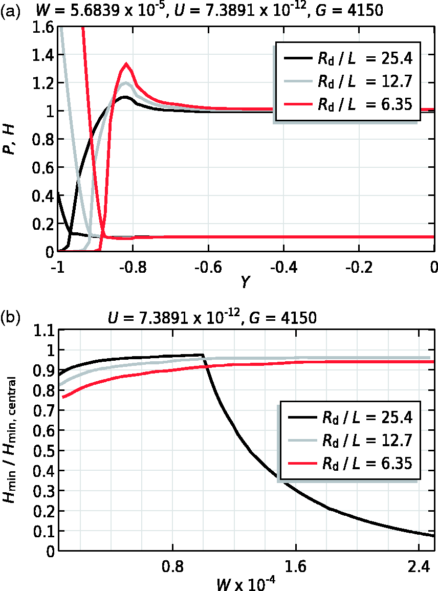
The aforementioned is amplified with increasing loads. One would then think that choosing a larger
A similar statement can be made about variations in the straight length of the roller (see Figure 12(a)). There is an optimum range for choosing an appropriate straight roller length as a too large value for Influence of roller straight length on (a) pressure and film thickness shape and (b) minima film thicknesses.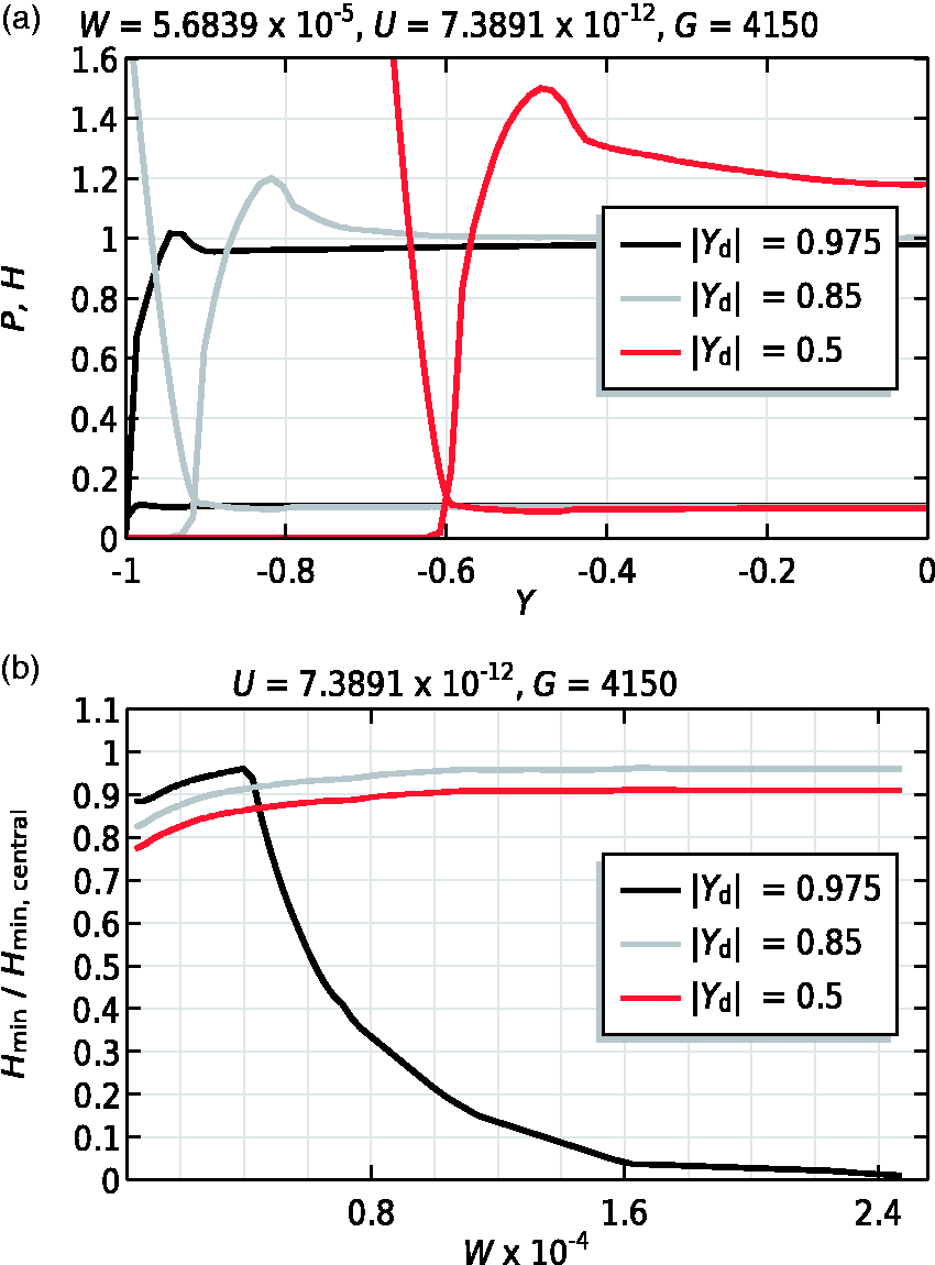
All these findings make it really hard to develop a robust correlation between absolute minimum film thickness and operating conditions, as axial profile design parameters play an equally important role. In fact, a good understanding of finite line contact behavior as a basis will lead to a better design of mechanical components in terms of film thickness and pressure distributions, and as a result, increase in service life.
Coated case
The influence of mechanical properties, in terms of coating stiffness and thickness, on the overall EHL behavior of a finite line contact will be discussed in this section. The reference operating conditions for the present results are identical to those presented in Table 1. In addition the coating thickness
In Figure 13(a) and (b), the influence of coating stiffness on the pressure and film thickness distribution is illustrated. Note that the case when Influence of coating elasticity 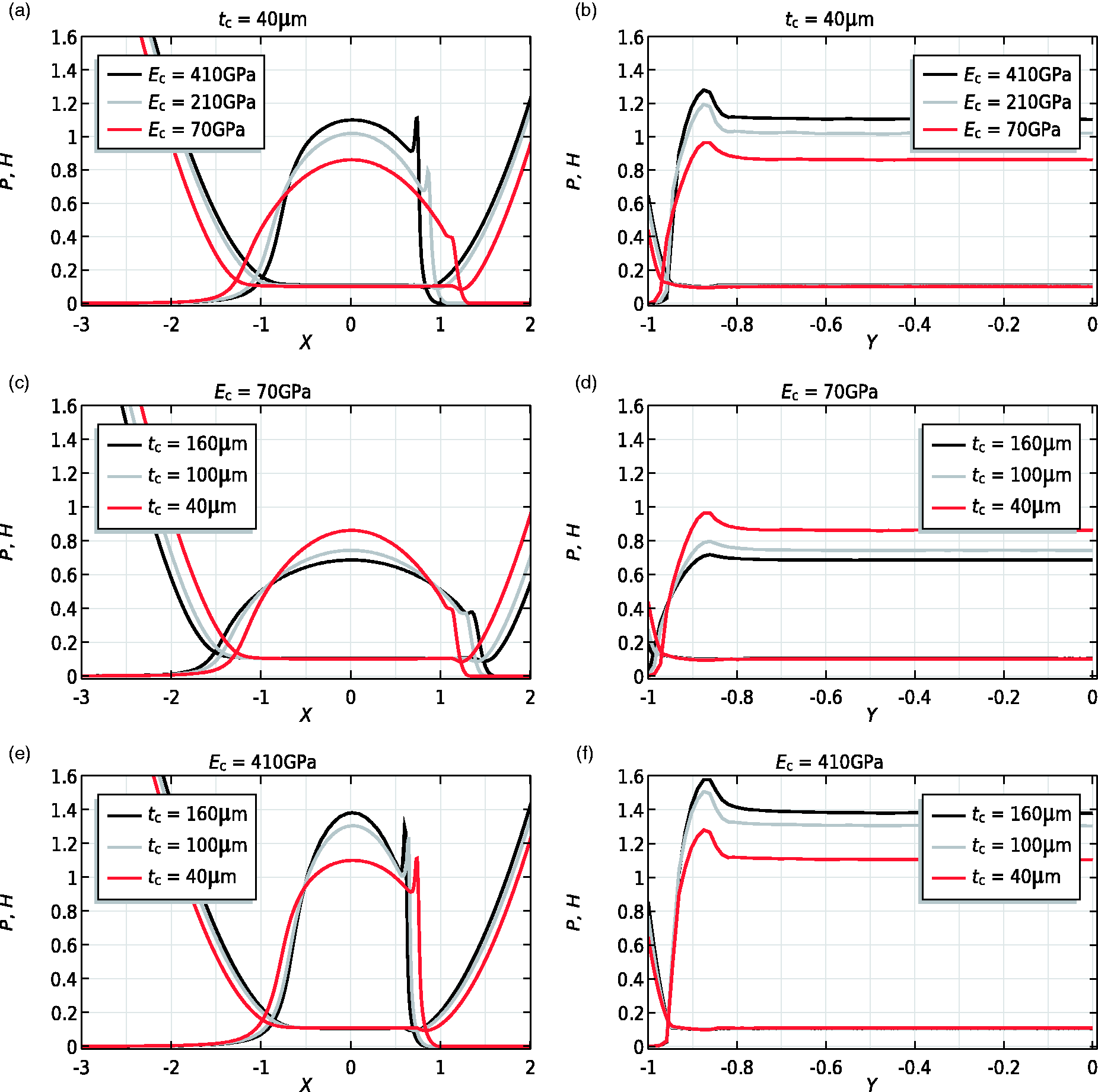
One can directly observe that with increasing stiffness of the coating the maximum pressure increases, while the contact width decreases. Furthermore, the pressure spike at the central plane and the secondary pressure peak at the rear of the contact increase in magnitude with increasing coating hardness. It seems obvious that with stiffer coatings higher pressures are expected, and to compensate for this (with fixed applied load), the contact area has to decrease. Taking a more detailed look at the behavior of minima film thicknesses, Influence of (a) coating thickness 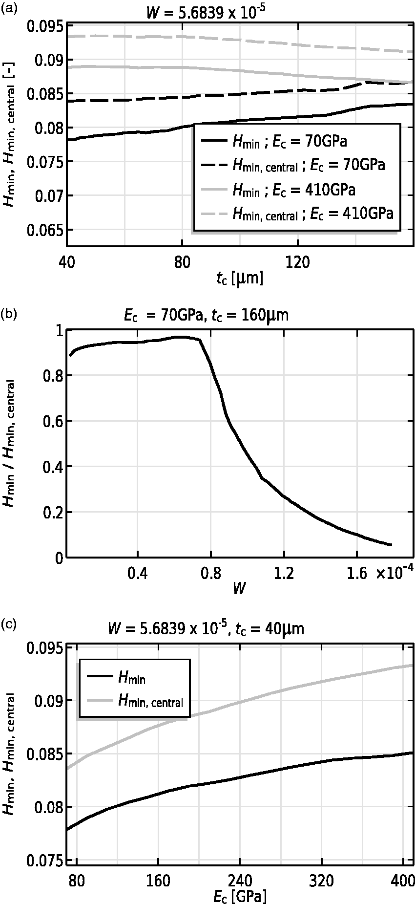
Now taking a look at Figure 13(c) to Figure 13(f), we see that the aforementioned phenomena, i.e. higher pressure with increasing coating elasticity, are amplified with increasing coating thickness. To be more specific, we see that for elastic coatings (
In line with previous findings, for coated contacts, we also see that for more elastic coatings the lubricated contact area is increased. This effect is further amplified with increasing coating thickness. The same also applies for increasing contact force, i.e. the lubricated contact area is also expanded with increasing load. Careful attention should be paid when dealing with elastic and thick coatings and high loads, in terms of minimum film thickness
Conclusions
In the present work, a FEM-based coated finite line contact model was developed. The lubricated conjunction between a roller with rounded edges on a plate was analyzed.
The developed model was quantitatively validated by means of representative results reported in literature. Good agreement between the results was obtained.
Parameter studies were carried out to investigate the influence of operating conditions, geometrical parameters (of axial surface profile) and coating mechanical properties on the overall EHL behavior of the contact. In line with previously reported findings, it is shown that the pressure and film thickness distributions for finite line contacts vary significantly different with applied load as compared to infinite line contact models. At increasing loads, the pressure distribution becomes more uniform in axial direction as long as there is space available for contact area expansion. When no space is left to compensate for higher loads, the secondary pressure peak at the extremities grows again and hence the absolute minimum film thickness decreases as per flow continuity demand.
Large round corner radii, large straight roller lengths, too elastic and thick coatings, all amplify the effect of increasing loads, i.e. the pressure profile expands in all cases to compensate for the applied load. When no space is left to compensate for higher loads, the secondary pressure peak at the extremities grows again and hence the absolute minimum film thickness decreases.
All these findings make it really hard to develop a robust correlation between absolute minimum film thickness, maximum pressure and operating conditions, as coating and axial profile geometrical parameters play an equally important role. The present results certainly contribute to a better understanding of lubricated and coated finite line contacts. This model can effectively be used for improved designs of finite line contact applications in terms of film thickness and pressure distributions, and thus ultimately, contributing to longer service life of the components.
Footnotes
Acknowledgements
This research was carried out under project number F21.1.13502 in the framework of the Partnership Program of the Materials innovation institute M2i (www.m2i.nl) and the Foundation of Fundamental Research on Matter (FOM) (www.fom.nl), which is part of the Netherlands Organization for Scientific Research (![]() ).
).
Declaration of Conflicting Interests
The author(s) declared no potential conflicts of interest with respect to the research, authorship, and/or publication of this article.
Funding
The author(s) received no financial support for the research, authorship, and/or publication of this article.