
Abstract
Frictional losses are one of the main causes of reduced energy efficiency in all machines and mechanisms. In particular, there is mounting pressure upon manufacturers of all forms of vehicle to comply with increasingly stringent legislation and directives with regard to harmful emissions. Therefore, reduction of friction has become an imperative issue. The traditional approach of dealing with surface material and lubricant formulation in isolation has been replaced by a lubricant–surface system approach. This paper presents multi-scale experimentation from nano/meso-scale lateral force microscopy of ultra-thin surface adsorbed films through to micro-scale precision sliding tribometry to investigate lubricant–surface friction optimisation within the mixed regime of lubrication, using lubricants with different organic and inorganic friction modifying species. These affect the parameters of the system, commonly used as input to models for mixed and boundary regimes of lubrication. Therefore, the precise measurement of these parameters at different physical scales is important. The study also makes use of detailed numerical predictions at micro-scale through combined solution of the average Reynolds equation as well as interaction of wetted asperities in mixed and boundary regimes of lubrication. Good agreement is found between the predictions and measurements at micro-scale tribometric interactions. Furthermore, the same trends are observed in testing across the physical scales.
Keywords
Introduction
Except for very few instances, reduction of friction is crucial in the efficient functioning of mechanical devices, as well as guarding against wear of contacting surfaces. For example, generated friction in the automotive piston–cylinder contacts can account for 4–6% of the total expended fuel energy.1,2 Lubrication and surface treatments have long constituted methods for mitigating the untoward effects of friction.
Sources of generated contact friction are viscous shear of a thin lubricant film and any direct interaction of contacting surfaces. Therefore, lubricant rheology (chiefly viscosity) and physical chemistry (composition) have been the subject of much development to improve lubricant load-carrying capacity whilst reducing its shear strength. This has led to the development of modern lubricants which are often subjected to widely varying contact and operating conditions, such as those encountered in an engine. Historically, reducing lubricant viscosity has been seen as a means of reducing in-cycle friction in cases where the regime of lubrication is dominated by hydrodynamics. The drawback in this approach is the reduced load-carrying capacity of the lubricant film which in turn can lead to direct interaction of contacting surfaces at higher loads. This is particularly a constraining factor in engines where a lower viscosity lubricant for piston–cylinder system is insufficient to withstand significantly higher generated pressures in the valve train system. 3 Therefore, a combination of lubricant additives such as viscosity and friction modifiers and coating or hardening of cam-follower pair surfaces is required, and thus a lubricant–surface system approach is sought.
For improved performance under widely varying operating conditions, a particular additive package is used to complement base oils to improve viscosity, thermal stability, formation of low shear strength ultra-thin boundary active surface films and for other functions. The efficacy of surface active additives is now fairly well understood in laboratory tests,4,5 where reductions in friction coefficients of up to 50%, compared with oils containing no friction modifiers, have been reported. 6 The effects of these additives are also measurable within fully fired engine tests,7,8 with Skjoedt et al. 9 having measured a reduction of 16% in friction mean effective pressure for a spark ignition engine at high load and with the presence of a molybdenum-based friction modifier.
There have been parallel developments in engineering of surfaces with hard wear-resistant coatings, improved surface topography through cross-hatching and honing, 10 and even the introduction of fine surface textures to act as reservoirs of lubricant in cases of poor contact kinematics, such as in reciprocating motions.10,11 These developments have improved mechanical efficiency of various contacts, such as seals, 12 bearings, 13 piston systems and other conjunctions. 14 Reductions of coefficients of friction by orders of 50% were found experimentally by Johansson et al. 15 for cylinder liners sprayed with carbide-nickel and a metal matrix composite coating in a single cylinder diesel engine. Electroplated nickel coating, co-depositing silicon (Ni-SiC) has been the coating of choice for in-cylinder applications because of its hard wearing and relatively low friction characteristics, particularly for high performance engines as reported by Howell-Smith et al. 10 and Mistry et al. 16 Another recent development has been boriding with favourable wear characteristics. Furthermore, borided steel yields a lower coefficient of friction in sliding contacts than the parent steel substrate, 17 especially after a short annealing process.18,19 Recent developments in the boriding process have reduced the fabrication times to around 15 min,20,21 with significant in-service improvement at elevated temperatures, which has resulted in commercially viable borided engine cylinders.
Nevertheless, these parallel lubricant and surface developments have taken place largely in isolation from one another, mainly because of commercial sensitivity. Yet to arrive at optimal solutions for given applications, an integrated approach is required with the perspective of the lubricant–surface as a system. Additives adsorb or chemically bond to the surfaces forming a completely new tribo-film layer, some of which act to reduce friction through reduced asperity contacts.22,23 Alternatively, some additives, such as graphite, offer a sacrificial, low shear strength layer over the asperities which can be replenished by the lubricant. For example, molybdenum disulphide in particular forms an adhesive bond to most substrates but the cohesive forces between the lamellae are fairly low and thus shear occurs readily between them. 24 It would not be prudent to assume that all friction modifying lubricant additives would respond in the same manner to any engineering surface material. It is, therefore, vital to understand the lubricant additive–surface coating combination, as noted by Neville. 25
Interaction of additive packages in tribological applications with the surfaces is rarely a static phenomenon; instead the tribo-film is subjected to dynamic formation and removal process. 26 Some studies have considered the mechanism of additive activation. Thermal and thermo-mechanical models have been presented for the additive bonding process.27–29
Although there have been significant advances in probabilistic macro-scale models of the mixed regime of lubrication,30–32 these have remained dependent on key input parameters for the prediction of boundary friction. Therefore, predictions using such models can be enhanced with the inclusion of data obtained from experimental measurements. Precise measurement of these is one of the main aims of the current paper, as well as noting the differences which emerge at different physical scales.
This paper advocates the lubricant–surface system perspective, with detailed analysis of sliding pairs under conditions which promote mixed regime of lubrication. A combined numerical–experimental investigation is carried out. Measurements of friction are taken both with a precision sliding strip-floating plate tribometer (micro-scale), as well as with an atomic force microscope (AFM) in Lateral Force Microscopy (LFM) mode (meso- and nano-scales). This multi-scale investigation of lubricant additives and surface coating combinations, suitable for in-cylinder applications is supplemented by numerical analysis using combined solution of the average Reynolds flow model for rough surfaces and boundary friction using an asperity interaction model. The combined multi-scale experimental-numerical approach has not hitherto been reported in literature, and is intended to contribute to the furtherance of knowledge in the field.
Numerical analysis
Modelling of sliding friction in the mixed regime of lubrication
The overall friction under the mixed regime of lubrication comprises viscous shear of a thin film of lubricant (viscous friction, fv), and direct interaction of counter face asperities (asperity friction,fa), thus

Boundary friction is generally described as
33


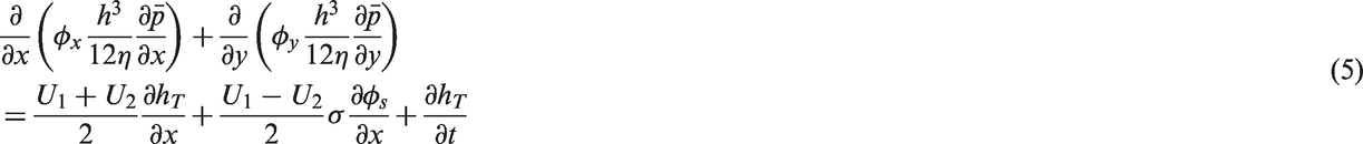
The Patir and Cheng’s average flow model,36,37 based on the Reynolds equation for flow through rough surfaces, is ideally suited to determine the lubricant film thickness h
The pressure and shear flow factors
The determination of the surface separation, h, and the pressure distribution in the contact also allows evaluation of viscous friction, fv, noted earlier in equation (1)


The pressure- and shear-induced friction factors
Method of solution
A second-order finite difference method is used to solve the average flow equation (5), using a point-successive over-relaxation scheme.
38
Pressure convergence is sought between successive iterations within an error tolerance of

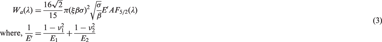
The asperity load-carrying capacity is then calculated using equation (3). The contact load-carrying capacity becomes

The load carried is then compared with the applied contact load in order to obtain quasi-static balance within an error tolerance of
Utilised lubricants and surface samples
The effect of surface material and topography, as well as lubricant rheology and physical chemistry upon conjunctional friction should be determined. This is the evolving approach in the lubricant–surface system perspective. There is also the effect of operating conditions, such as the applied load and contact kinematics (shear characteristics), which should also be taken into account, thus determining the prevailing regime of lubrication.
The tested lubricants were blended in order to ensure consistent distribution of an additive package in the lubricant, particularly various friction modifiers. The friction modifiers used in the lubricant do not significantly affect its viscosity under low shear rate conditions, 39 such as those experienced under the sliding tests with the aforementioned tribometer. Therefore, lubricant viscosity can be considered to be fairly consistent across the range of employed lubricants. To verify this, the viscosity of the utilised lubricants was measured at 20.7℃, the ambient temperature at the testing condition. It was found that there was less than 2% variation in viscosity for the range of lubricants used. This removes the effect of viscosity variation for the range of lubricants used, when comparing the measured friction under the stated testing conditions.
Four lubricants were used in the test programme, three of which contained various friction modifiers. The test lubricants were:
Group III base oil only ( Group III base oil with the addition of 0.5 wt% of an organic friction modifier, hereinafter referred to as FM1 ( Group III base oil with the addition of 0.5 wt% of another organic friction modifier, hereinafter referred to as FM2 ( Group III base oil with the addition of 0.5 wt% of an inorganic friction modifier, hereinafter referred to as FM3 (
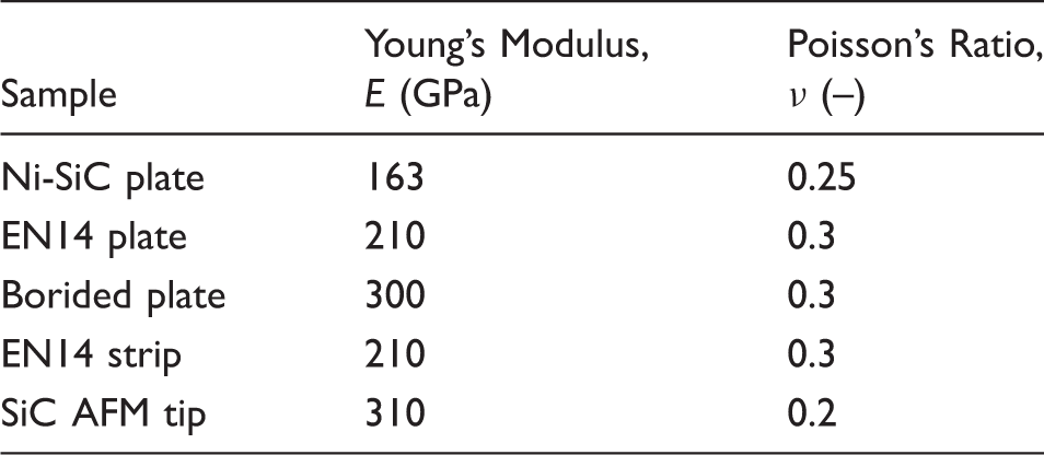
Material properties.
Combined measured surface topography parameters.
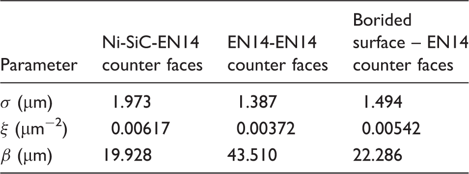
Figure 1 shows the probability density distributions of the surface data for the sampled flat surfaces, convoluted with the counterpart sliding strip face-width topography.
Surface height probability density distributions for the sample plates convoluted with those of the flat ring.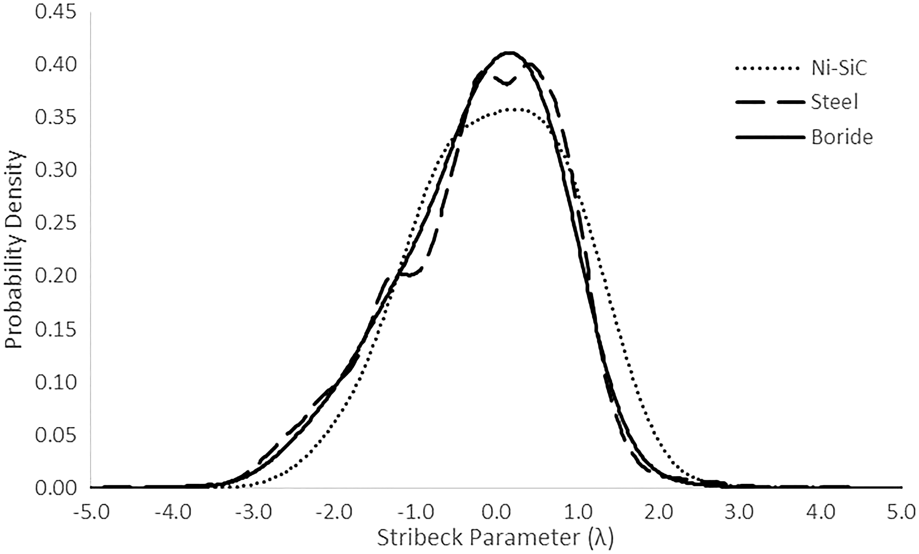
Figure 1 shows that the surface height distributions are approximately Gaussian, justifying the use of Patir and Cheng’s average Reynolds equation.36,37
Two parameters remain to be determined for the prediction of any boundary friction:
Lubricant–surface system parameters measured by AFM/LFM
A Veeco Dimension 3100 AFM was used for the nano-scale investigation of the lubricant–surface–additive systems. The schematic of the AFM working mechanism is shown in Figure 2.
Schematic of the AFM and the optical deflection measurement technique.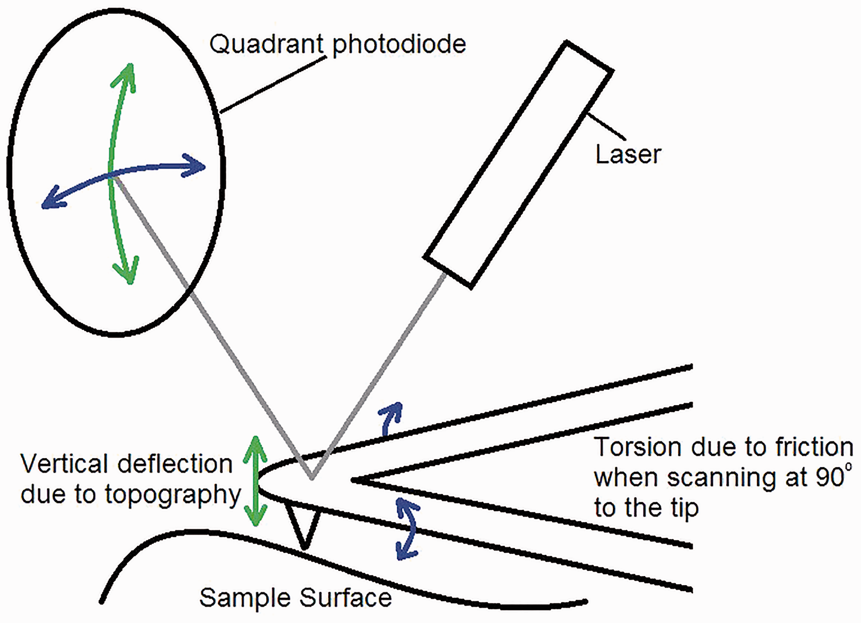
The AFM was used in lateral force mode (LFM) mode to determine the threshold for non-Newtonian shear stress of the lubricant
A “blind calibration” approach was applied for calibration of each contact probe tip in the LFM measurements, in line with the work of Buenviaje et al. 40 This calibration is performed by measuring the lateral deflection of the reflected laser (in Volts) while scanning at known applied loads on a calibration sample. By plotting the recorded friction against the applied load, a calibration factor is determined for the tip used as long as the coefficient of friction for the materials used is known a priori. In the calibration procedure applied here, a silicon-nitride tip was used against a standard silicon carbide calibration sample with a contact coefficient of friction of 0.19, as given by Buenviaje et al. 40 and used by Styles et al. 41 and Chong and Rahnejat 42 with application to automotive cylinder technology.
Determining the coefficient of boundary shear strength,
, under dry contact condition
The test samples were measured under dry contact conditions for a range of applied loads. Graphs of load versus friction are shown in Figure 3, where the gradient of these variations represents the value of ς in each case.
Friction against load for the sample materials under dry conditions as measured with LFM.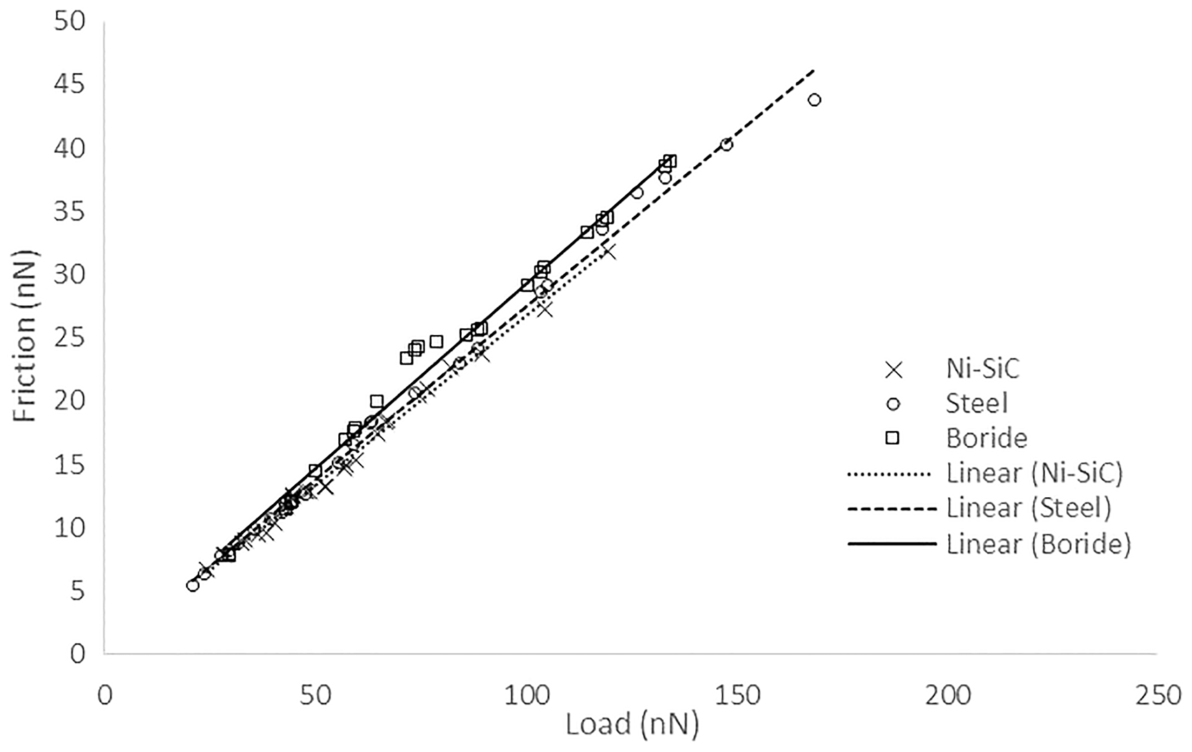
It can be seen that the Ni-SiC sample has the lowest coefficient of boundary friction (
Determining the Eyring shear stress,
The three chosen surface materials were further tested in combination with the additive-free base oil to determine the Eyring shear stress,
During the loaded scanning process of wet LFM, the tip of the AFM probe and the surface are assumed to undergo localised Hertzian deformation, leading to a flat contact made up in part of direct contact between the tip and the specimen surface and partly of a trapped adsorbed lubricant layer. The shearing of the tip across the surface is, therefore, the combined effect of the shear strength of the asperity junctions as well as shear of the entrapped or adsorbed lubricant layer. The total shear stress at the tip of the AFM probe is therefore given as
43

The apparent contact area can be determined using the classical Hertzian theory as


At higher shear rates and/or pressures, the lubricant behaviour becomes non-Newtonian, where viscous shear stress can be obtained as

There are two unknowns that remain to be determined from equation (10), α and 
Applying these assumptions to the lowest loads for each sliding speed enables the determination of α as a load and sliding speed-dependent variable and reapplying the same allows the determination of
Comparing equations (13) and (14) indicates that the lubricant shear stress becomes independent of sliding speed when the lubricant traction becomes non-Newtonian if a constant applied pressure is maintained.
Figure 4 shows the measured lubricant shear stress (in this case using the base oil) against the sliding speed of the AFM tip. It is clear that the lubricant shear stress is largely independent of the surface materials. It is also clear that the assumption of an initial Newtonian shear during the formation of a conjunctional film at low sliding speeds is valid (Figure 4).
Lubricant shear stress variation with sliding speed for the sample materials under ‘wet’ AFM tests.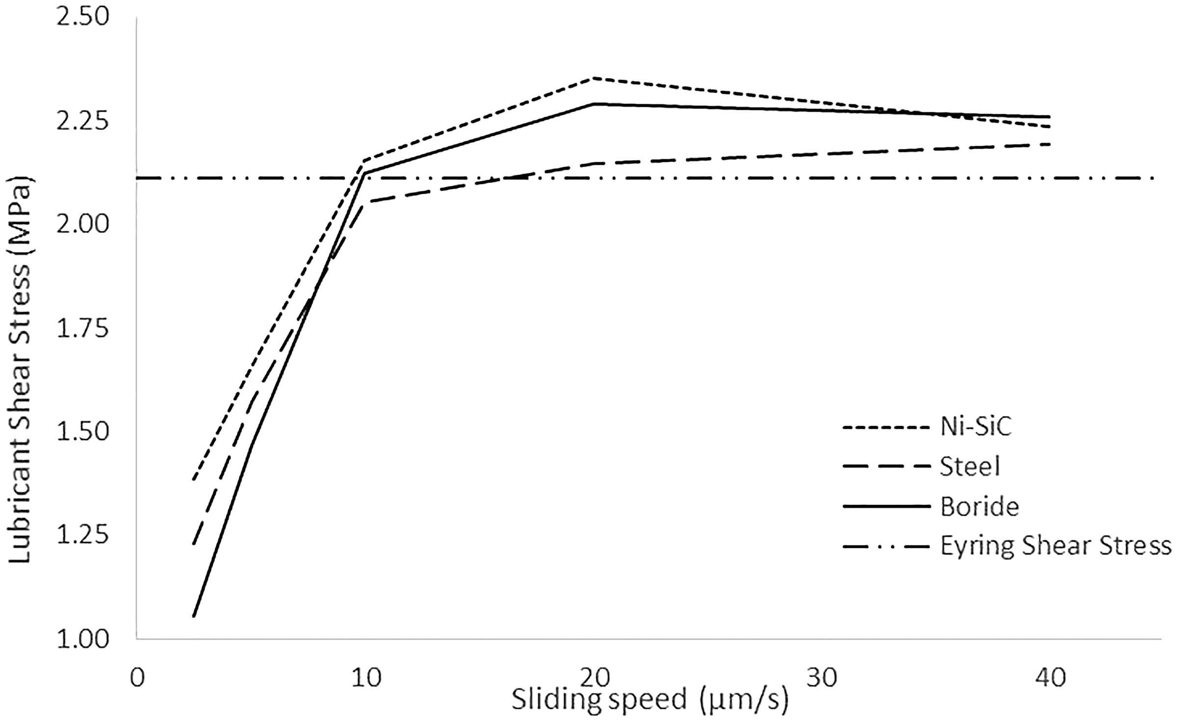
From the variation in the lubricant shear stress, it is clear that the lubricant displays a shear thinning behaviour and the Eyring shear stress is reached around
The Eyring shear stress is determined as the shear stress at which the lubricant commences non-Newtonian behaviour. This is discernible in Figure 4 although only a limited number of sliding speeds are used in this study. The limiting shear stress of the lubricant is more evident due to the plateauing of the shear stress curve, providing a greater number of points with which to measure it.
Variation of friction with applied tip load at different tip sliding speeds can be measured as shown in Figure 5 for the case of the uncoated EN14 steel specimen. In all cases, friction is initially reduced rapidly with an increasing sliding speed, indicating the formation of a thin lubricant film in the tip–sample conjunction due to lubricant entrainment. Thereafter, any further reduction in friction becomes more gradual, indicating a loss of proportionality with the sliding speed. This heralds the onset of non-Newtonian shear behaviour.
Measured friction against sliding speed for various tip loads for the steel sample under ‘wet’ AFM tests.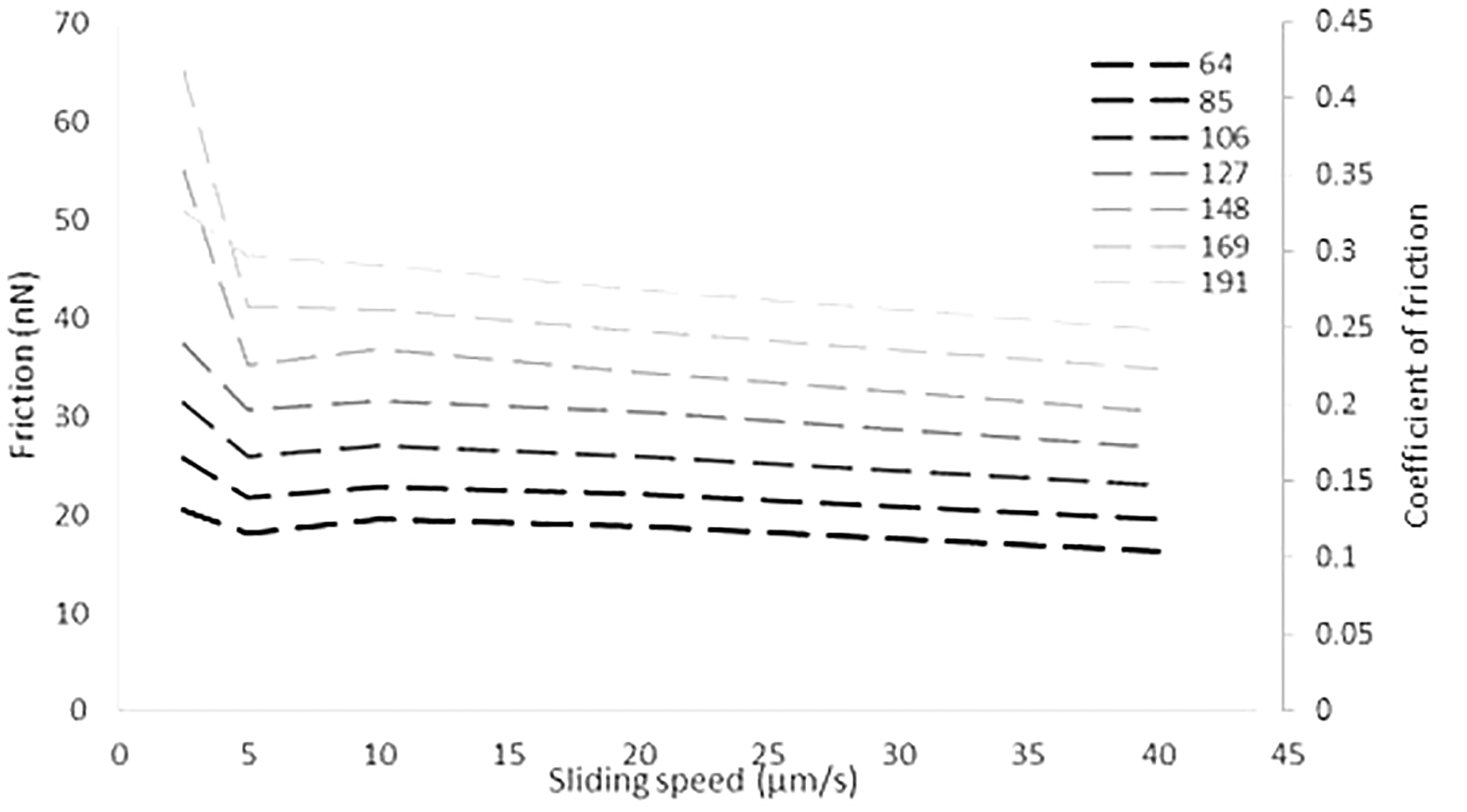
Results and discussion
Measurement of friction using a reciprocating slider test rig
Frictional performance of the test materials with base oil was ascertained using an in-house built sliding strip tribometer shown in Figure 6. The tribometer is used to measure the generated friction between two rough surfaces. A sliding strip with a parabolic face–width contacting profile slides on the flat specimen samples, described in the Utilised lubricants and surface samples section. The flat specimen is mounted onto a floating flat plate, which is supported by low friction bearings. A film of lubricant intervenes between the contacting surfaces, through which the plate is dragged by the generated friction. The inertial dynamics of the base assembly is measured by piezo-resistive load cells (Figure 6) and equates friction as
The sliding strip tribometer and the schematic of the mechanism.
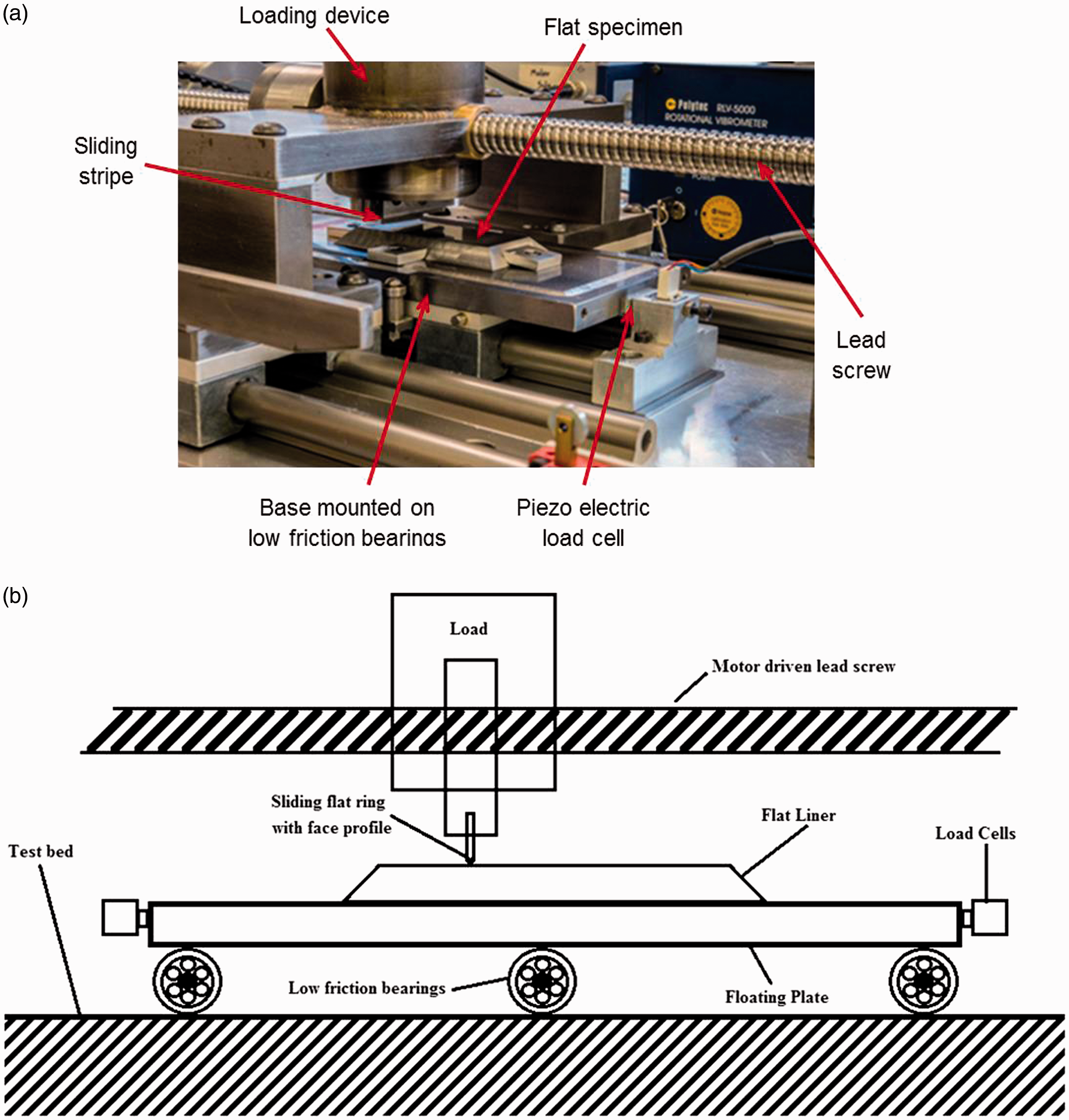
Ten friction measurements were undertaken with each specimen (steel substrate, borided surface and Ni-SiC coated sample). In each case, the measurements were averaged for the same 25 mm section of the sliding stroke once the sliding strip had reached a constant speed of 24 mm/s. These are typically at low speeds, representative of the sliding speed of the piston compression ring in contact with the cylinder liner in the vicinity of the top dead centre reversal. This is the region in which mixed and boundary regimes of lubrication are prevalent. 41 The sliding strip has a parabolic face profile with a radius of curvature of 50 mm. The tests were conducted at room temperature (18℃) with an applied load of approximately 12 N, resulting in a contact pressure of 4 MPa, comparable to those in typical piston ring–cylinder liner conjunctions. 47
A 2 ml volume of additive-free base oil is applied to the surface and allowed to spread to a uniform coverage for all the three tested surface materials. The measured friction for each flat surface specimen, averaged from 10 runs, can be seen in Figure 7.
Average coefficients of friction recorded for the three surface materials with the additive free base oil as measured with the in-house reciprocating slider rig.
Figure 7 shows that the materials retain the same ranking as those obtained through LFM measurements of dry contacts. The error bars indicate one standard deviation in the measured friction throughout the sampled section of the sliding stroke (∼0.005). It is interesting to note that the measurements with the tribometer are at a larger physical scale than those using LFM, yet the outcome remains the same, even under boundary or mixed regimes of lubrication. Therefore, the tribometric measurements can be considered as a validation of more complex and sensitive LFM measurements.
Assessing the combined additive–surface performance using the reciprocating tribometer
To assess frictional performance of various lubricant–surface systems, specially blended lubricants (the Method of solution section) are used in conjunction with the sliding strip tribometer. The same procedure as in the previous section was employed to obtain percentage reduction in friction, thus ascertaining the effectiveness of the various friction modifiers in adsorbing/adhering/bonding to the various sample materials. Ten runs were conducted at the slow sliding speed in order to attain activation energy for the boundary active species prior to 10 measured runs that were averaged to attain friction measurements. At the low sliding speeds, thermally-assisted atomic hopping occurs due to combined pressure loading and shear.48,49 The slow stick–slip motion of the strip, promoting atomic hopping and thermal activation of boundary active lubricant species, is manifested by the fluctuating friction trace shown in Figure 8.
An example of recorded friction trace with the tribometer.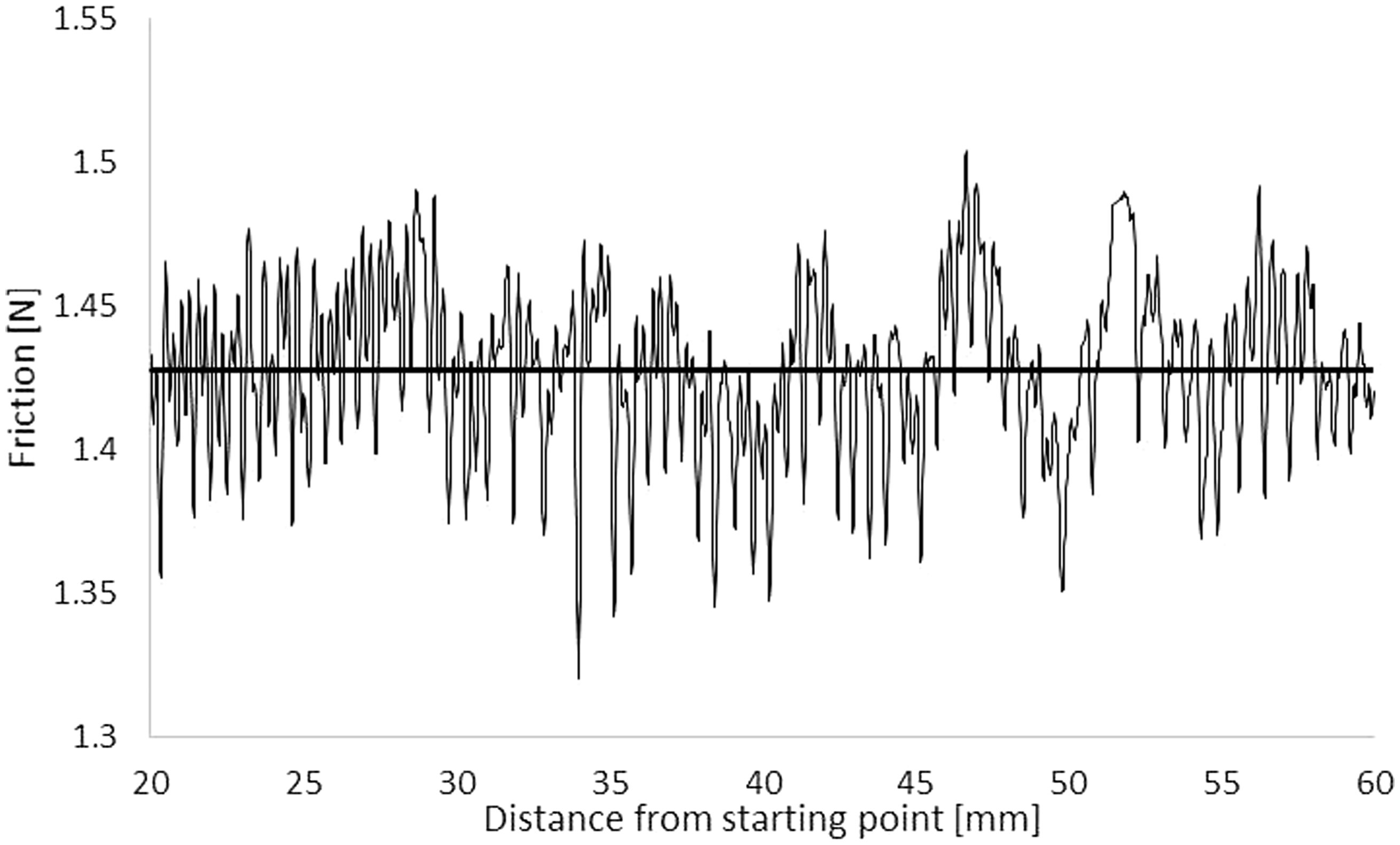
The reductions in the coefficient of friction with the formulated lubricant and each friction modifier (described in the Method of solution section) can be seen in Figure 9. The error bars are within one standard deviation in the measured friction throughout the sampled section of the sliding stroke.
Coefficient of friction for the three surface materials with the lubricant containing different friction modifiers as measured with the in-house reciprocating slider rig.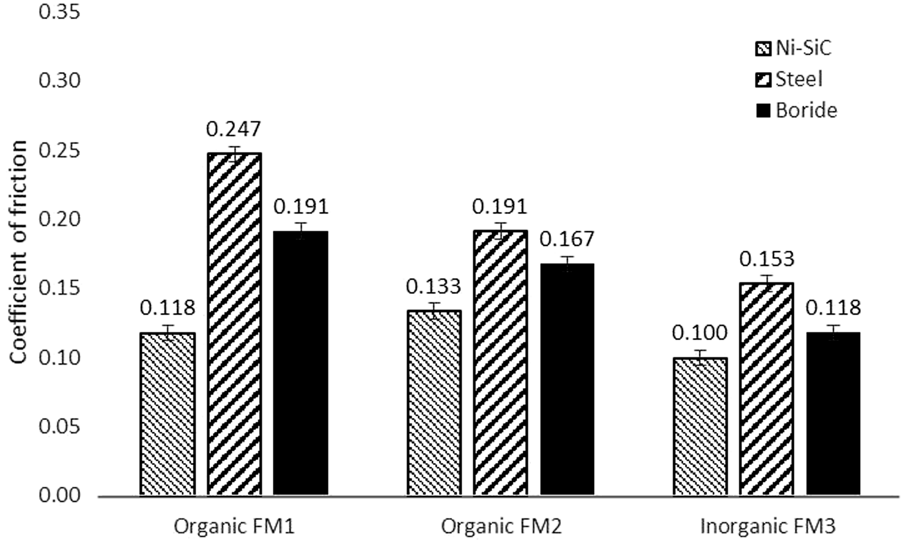
The results shown in Figure 9 suggest that the inorganic friction modifier (FM3) formulated oil is the most effective at reducing friction. Additionally, there is a change in the ranking order of the surface materials as the borided sample shows improved frictional performance over the steel substrate with the inclusion of all the friction modifier variants. This suggests that the applied loading and shear have resulted in overcoming the energy barrier to activate additive adsorption to the tested surfaces. As the inorganic friction modifier provided the most reduction in friction for all the tested specimens, further testing under LFM was carried out with this formulated oil.
Assessing the combined additive–surface performance using AFM
The three surface materials were tested with the formulated lubricant, comprising the inorganic friction modifier, FM3. The LFM measurement results for these are shown in Figure 10.
Coefficient of friction for the three surface materials with the formulated lubricant using the inorganic friction modifier FM3 as measured with LFM.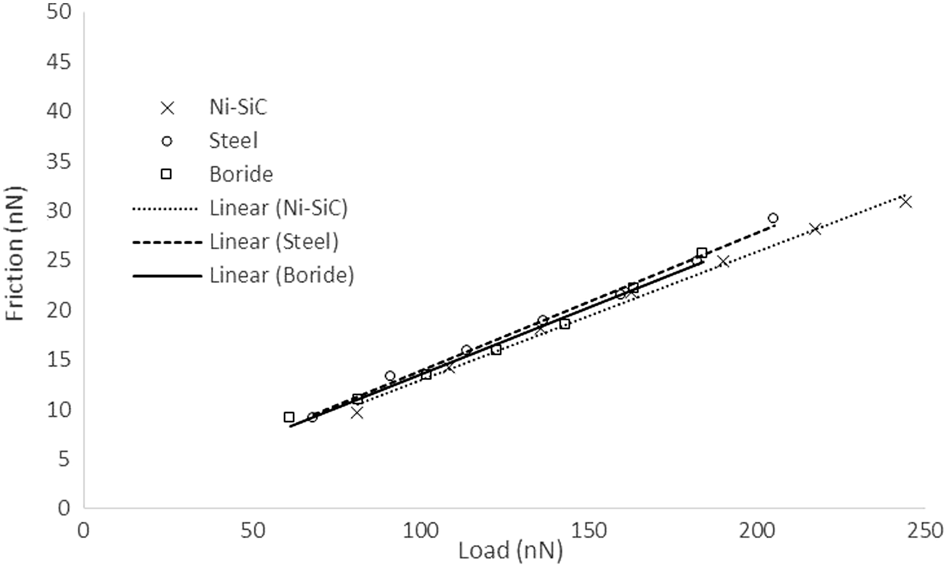
The results show that the surfaces generate similar frictional characteristics. The Ni-SiC coating provides the least coefficient of friction at 0.130, whilst the other surfaces yield very similar results; 0.139 for steel and 0.135 for the borided surface. These values are within 8–20% of those measured using the tribometer. The sources contributing to this difference can be manifold, mainly because of different rates of lubricant entrainment into the contact (sliding speed and contact geometry), and extent of loading, thus activation energy for the FM3.
The coefficients of friction recorded above are those measured for the entire contact. However, the contributions from the individual components of friction, shear of a bulk lubricant film and boundary interactions (including a thin adsorbed film of FM3) would be of interest. A basic analytical calculation using the theoretical model can be instructive.
It would be reasonable to assume that any bulk lubricant film contribution to load-carrying capacity and shear behaviour would be the same as that determined in the case of base oil analysis. Therefore, it is possible to determine the boundary coefficient of friction for the direct surface interactions for each of the surface material as50


The resulting coefficients of friction for direct boundary friction, using the measured data from LFM, can be seen in Figure 11.
Coefficients of friction for the boundary contribution of the lubricated contacts with the inorganic friction modifier, FM3, as measured with LFM.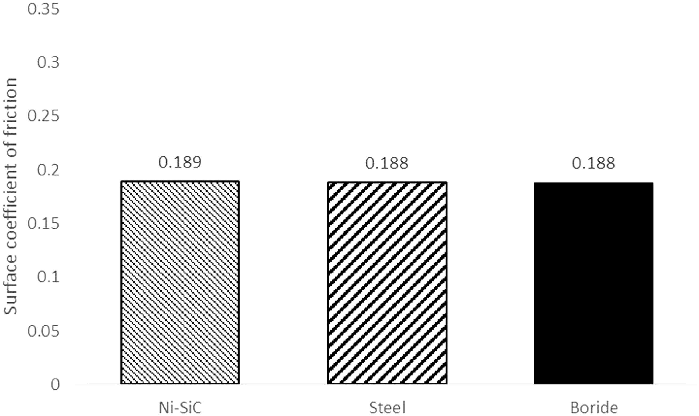
These are reduced from their corresponding values obtained for their dry untreated counterparts in Figure 3, indicating the adsorption of the friction modifier to the surfaces of the samples post activation by the scanning of the AFM probe.
The similarity between these coefficients of friction indicates that the surface material is not a key variable in contact friction when the scanning probe tip has presumably exceeded the activation energy barrier of FM3. The results suggest that FM3 bonds indiscriminately to all the three examined surface materials largely to a similar extent.
It would be instructive to ascertain whether a similar mixed regime of lubrication exists at the larger physical scale in the contact conditions promoted under tribometer conditions. For this purpose, numerical analysis is carried out using the outlined theory in the Numerical analysis section. Prediction of boundary friction for the three surface materials is based on the measured values of ς under wet LFM.
Numerical predictions
The performance of the three samples with base oil can be predicted through numerical analysis, described in the Numerical analysis section. The results obtained correspond to the experimental conditions reported for the sliding strip tribometer (the Determining the coefficient of boundary shear strength, Coefficients of friction predicted by the model for the reciprocating slider rig lubricated with the base oil.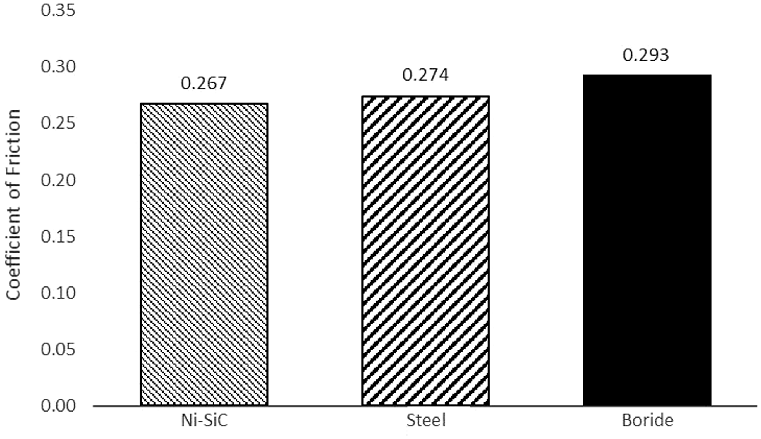
Using the LFM measured coefficients of friction in the model and simulating the condition of the reciprocating sliding rig, Figure 13 shows the predicted coefficients of frictional by the model.
Coefficients of friction predicted by the model for the reciprocating slider rig lubricated with the formulated oil including inorganic friction modifier (FM3).
Figure 13 suggests that the difference in the measured friction between the materials by the sliding tribometer with the inorganic friction modifier FM3 is not due to the inherent friction of the surface material, but is because of the macroscopic topography of the surfaces and their combined effective elastic modulus of the contacting pairs (Young’s moduli of elasticity and Poisson’s ratios). Therefore, differences in boundary lubrication contributions at different physical scales can be explained, when a combined numerical analysis and experimental investigation are carried out, which is the main contribution of the work reported here.
The differences in magnitude between Figures and 9 (tribometric measurements) and 13 (numerical predictions) highlight the necessity for experimental work at the meso-scale. Even with the improvements in numerical techniques, a comprehensive friction model that accounts for a strong experimental database is required.
Conclusions
Overall, the study demonstrates that a lubricant–surface combination approach can lead to an understanding of the possible routes for friction reduction in particular applications. Key parameters of importance are surface topography and material composition (coating and substrate) as well as the lubricant additive package. The same base oil is used in all the lubricants tested. This ensures the same load-carrying capacity with surfaces of different material, but nominally similar topography. No additive package, aside from different friction modifying species, is used. Therefore, the differences noted are due to the interaction of friction modifiers and different surface material. Extensive testing and numerical predictions are carried out to ascertain the differences noted in a multi-scale investigation. Key parameters such as boundary shear strength of asperities and Eyring shear stress are required for numerical predictions which are ultimately of critical importance as design guides for many applications. The measurements carried out and their subsequent inclusion in the numerical analysis show good conformance between the predictions and experimentation in the micro-scale.
The overall conclusion of multi-scale testing is that for nominally similar surface topography, it should be possible to select an “optimum” friction modifier as an additive for a given surface material to attain least friction. The results also show that when sufficient surface coverage of a friction modifier is made, through sliding activation at the nano-scale (LFM) the effect of surface material (for a single asperity contact) can become indiscernible. This is not seen at the larger physical scales (tribometry) where there is a clear difference in the frictional performance of the surface materials. The problem of the scale-dependence of the coefficient of friction becomes evident through a comparison of these results. This finding is not expected to be of a generic nature for all friction modifying species.
Footnotes
Declaration of Conflicting Interests
The author(s) declared no potential conflicts of interest with respect to the research, authorship, and/or publication of this article.
Funding
The author(s) disclosed receipt of the following financial support for the research, authorship, and/or publication of this article: The authors would like to express their gratitude to the Engineering and Physical Sciences Research Council (EPSRC) for the sponsorship of this research under the Encyclopaedic Program Grant (![]() ).
).