
Abstract
Euplectella aspergillum, a naturally occurring deep-sea sponge, possesses a skeletal architecture that uniquely combines mechanical robustness with outstanding energy, sound, and thermal absorption capabilities. Its geometry offers extraordinary promise as an inspiration for engineering design and shows tremendous scope for further enhancement in its mechanical and energy absorption properties. This study harnesses its architecture to develop novel multi-layered lattice structures, fabricated through material extrusion additive manufacturing, and systematically investigates their compressive and flexural performance. These newly developed multi-layered lattices demonstrated a 50% enhancement in Young’s modulus, a 138% increase in compressive strength, and nearly double (96%) the specific energy absorption compared to conventional lattices of identical density and weight. Ashby plots further reveal that these lattices achieve the highest SEA among all studied layered architectures, including those at higher densities—a testament to the efficiency of the sponge-inspired layering strategy. These findings establish a new paradigm for tailoring mechanical performance in bio-inspired structures with layering strategies. This work lays a strong foundation for the future development of high-performance, multifunctional lattices and sandwich lattice cores with applications across aerospace, defense, energy absorption systems, and beyond.
Keywords
Introduction
Nature-inspired cellular structures, featuring periodic unit cell arrangements in two or three dimensions, include plate, honeycomb, strut, and triply periodic minimal surface lattices.1–3 These architected materials have attracted significant attention owing to their high specific strength, stiffness, and energy absorption capacity, which make them promising for diverse engineering applications.4,5 Over the years, numerous bio-inspired lattice structures have been investigated, offering new opportunities for structural and functional optimization. 6 Nature, with millions of years of evolution, has developed intricate multiscale and hierarchical features that deliver exceptional performance across various length scales. Such evolved features provide a rich source of inspiration for the design of engineering structures with unique property combinations. Accordingly, bionics has emerged as a rapidly growing field, driving innovation in material design and enabling novel applications in advanced engineering systems.7,8
Among the wide range of bio-inspired concepts, several studies have translated natural architectures into lattice designs with tailored mechanical properties. In particular, deep-sea sponge-inspired structures, especially those mimicking Euplectella aspergillum, have demonstrated remarkable buckling resistance and energy absorption.7–15 For example, Fernandes et al. 9 introduced a glass sponge-inspired lattice with a hybrid tessellation of open and closed cells. Finite element simulations and quasi-static experiments under compression and bending confirmed their superior buckling resistance and isotropic in-plane properties, outperforming alternative configurations such as the single-diagonally reinforced, all-diagonally reinforced, and square lattices. Building on this, Sharma and Hiremath 7 investigated the in-plane energy absorption of these structures, revealing a stable plateau region during deformation and failure through local buckling. In another study, Sharma and Hiremath 10 investigated the impact of using two materials—a stiff material (PLA) and a compliant soft material (TPU)—on the in-plane and out-of-plane properties of deep-sea sponge lattices, comparing them to monolithic lattice structures. Their results showed that while the energy absorption capacity of the bi-material lattice was lower than that of the PLA-only lattice in both directions, the crushing force efficiency notably improved. Zhang et al. 11 found that increasing wall thickness enhanced energy absorption and significantly affected deformation modes and Poisson’s ratio. Ma et al. 12 compared the auxetic behavior and mechanical properties of deep-sea sponge-inspired with various honeycomb structures, including elliptical annular re-entrant, double arrowhead, re-entrant, chiral, and star configurations. The sponge-inspired design outperformed all counterparts, exhibiting superior auxetic characteristics, higher energy absorption, and enhanced mechanical performance. Sharma and Hiremath 13 compared the in-plane behavior of the conventional sponge-inspired structure with a modified configuration consisting solely of closed cells, achieved by incorporating double diagonal members passing through all cells. Although the modified structure had a higher relative density, the elastic properties were normalized to account for this weight difference. Both numerical and analytical results demonstrated that the closed-cell design exhibited a significantly higher effective elastic modulus.
Beyond planar structures, researchers have extended sponge-inspired lattices to strut-based and tubular configurations for defense, medical, aerospace and marine applications. For example, Wang et al. 14 proposed a strut-based lattice derived from the deep-sea sponge architecture and compared its performance with conventional BCC, FCC, and Octet lattices in terms of structural stability, energy absorption, and strength. Their results revealed that the bio-inspired design consistently outperformed all conventional counterparts across these performance metrics. Chen et al. 15 studied the buckling behavior and energy absorption of sea sponge-inspired tubular structures with various cross-sections, including circular, square, hexagonal, triangular, and rectangular, using both experimental and numerical methods. Their findings revealed that the hexagonal design offered the greatest buckling resistance, while the circular one excelled in energy absorption. Zhang et al. 16 further investigated the axial, radial, and bending behavior of bio-inspired tubular structures, together with the same alternative designs that Fernandes et al. 9 had previously used for planar benchmarking, but here adapted into tubular form. They found that sponge-inspired tubular structures excelled under axial and bending loads and performed comparably to the best design under radial loading. Similarly, Chen et al. 17 conducted a numerical investigation on the same structures under axial and radial compression, torsion and bending. Their findings outlined that the nature-inspired design surpassed other structures in the torsional and flexural rigidity. Li et al. 18 compared the bending, torsion, and axial compression loads of the tubular sponge structure with those of the hexagonal counterpart. Their results indicated that the deep-sea tubular structure excelled under all loading scenarios. Sharma et al. 19 investigated the energy absorption behavior of deep-sea sponge tubular structures under low-velocity impact. They found unit cell length affected impact fluctuations, height influenced deformation, and decreasing the loading angle increased peak crushing force and energy absorption without altering the deformation mode.
Wang et al. 20 investigated the out-of-plane behavior of deep-sea sponge-inspired structures under quasi-static loading, comparing them to those benchmarked by Fernandes et al. 9 The results showed that the bio-inspired lattice outperformed all other designs in energy absorption, mean crushing force, and crushing force efficiency. Another out-of-plane investigation was carried out by Li and Sun, 21 where they compared various sandwich structures of similar relative density with cores of deep-sea inspired design, hexagonal honeycomb, and other square honeycombs with different diagonal reinforcement styles (structures used for benchmarking in 9) in terms of low velocity impact penetration. Their results indicated that the sandwich structure with a nature-inspired core exhibits the highest absorbed energy, impact penetration resistance, and stiffness among all compared structures. Li et al. 22 found that density gradation slightly enhanced energy absorption in the out-of-plane direction of the deep-sea sponge cellular structure, but significantly improved its crushing force efficiency.
While previous studies primarily emphasized how bio-inspired lattices surpassed conventional 2D structures in buckling resistance and energy absorption, relatively little attention has been given to advancing these architectures themselves. In particular, most efforts have focused on demonstrating superiority over traditional counterparts rather than exploring strategies that could further strengthen their mechanical performance, improve flexural response, and expand their potential applications.
This study introduces a layering-based design strategy aimed at enhancing in-plane mechanical properties while maintaining similar relative density. Although the mechanical robustness of Euplectella aspergillum-inspired structures has been well established, layered architectures of these deep-sea sponge-inspired lattices remain largely unexplored, despite evidence from other 2D lattices showing that layering can significantly improve mechanical performance.23,24 To address this gap, the present work leverages additive manufacturing to fabricate complex multi-layered lattices and systematically investigates their mechanical response. Recognizing that the vertical members of deep-sea sponge-inspired lattices often fail by local buckling before material yielding, this study evaluates the potential of layering to suppress local buckling in these members and, in turn, to enhance energy absorption and load-bearing capacity. Importantly, this first-of-its-kind approach evaluates not only the influence of layering on in-plane compression but also its impact on flexural performance, aiming to deliver a broader and more robust understanding of the mechanics of layered bio-inspired lattices. The following sections outline the design methodology, 3D printing process, experimental testing, and key findings.
Materials and methods
Designs
A two-dimensional lattice unit cell inspired by the skeletal system of deep-sea sponge (Figure 1(a)), serves as the fundamental building block for all designs in this study. The unit cells were modeled in SOLIDWORKS v2023 with a cell size of 25 mm and a relative density of 35.9%. Compression and flexural specimens were derived from a periodic unit cell structure: compression cubes (2 × 2 × 2 lattices) and flexural beams (4.5 × 1 × 1 lattices), extruded uniformly in the out-of-plane direction to form uniform cube (U) and beam (B-U) structures, as shown in Figure 1(b). The half cell for the flexural beam is to ensure an odd number of cells, allowing the bending load to be centered during testing. The U structures, previously studied in the literature,
9
represent our baseline for comparison with the novel multi-layered lattices developed in this study. The relative density was set to the minimum value required for printability and to study the buckling behavior of the thin walls of the structure. Since the deep-sea sponge unit cell consists of both open (E) cells with no internal members and closed (F) cells with two diagonal members, two variations of the B-U structure were investigated, one with the central empty cell positioned under the top roller (B-UE) and the other with the central full cell located under the top roller (B-UF), obtained with a 180° angle turn of B-UE. (a) Deep sea glass sponge (reprinted from Ref. (
35
), with permission from Elsevier) inspired unit cell with dimensions (b) Uniform lattice structures of compression cubes (U) and flexural beams (B-U) with upper empty central cell (B-UE) and upper full central cell (B-UF), (c) multi-layered lattice structures of compression cubes (ML) and flexural beams (B-ML) with 2-layers (ML2, B-ML2), 4-layers (ML4, B-ML4) and 6-layers (ML6, B-ML6).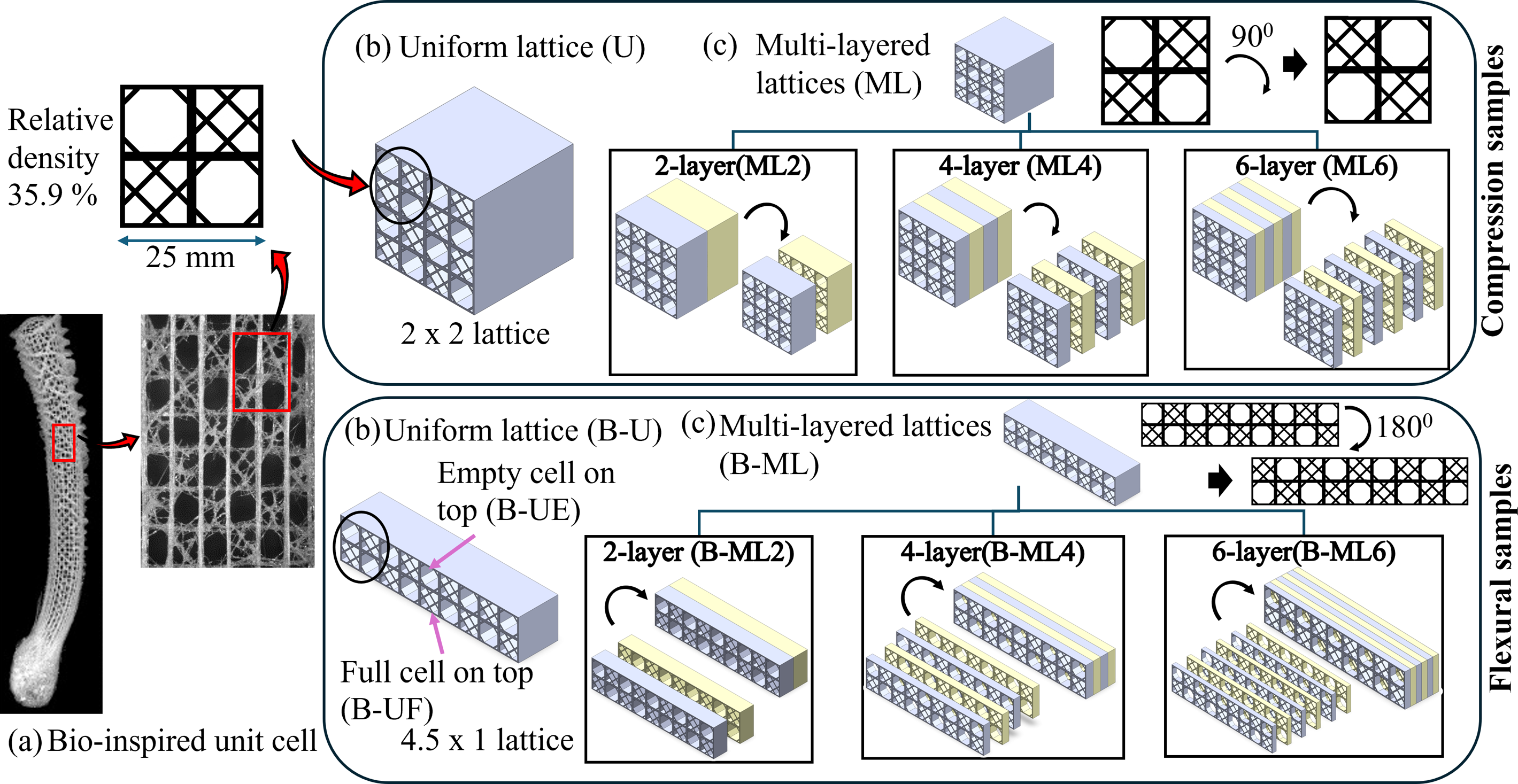
For generating the multi-layered cube (ML) and beam (B-ML) structures, the unit cell was rotated 90° for compression and flexural samples to append as an adjacent layer. To generate the multi-layered designs, the U structure was divided into two, four, and six equal layers along its extruded depth, with the layers alternating between the original and a rotated orientation. This produced 2-layer, 4-layer, and 6-layer cubes (ML2, ML4, ML6) and beams (B-ML2, B-ML4, B-ML6). In these configurations, the second, fourth, and sixth layers adopted the rotated orientation, while the first, third, and fifth retained the original, as shown in Figure 1(c). Importantly, all structures were designed with the same overall volume and relative density (volume fraction). The only variation introduced was the rotation of the unit cells between layers, therefore, any observed differences in mechanical response arise purely from the layering effect rather than differences in mass or weight.
Compression tests were conducted on the cubes to evaluate buckling behavior and mechanical properties such as Young’s modulus, yield strength, and specific energy absorption (SEA). The beam structures were subjected to flexural studies in two different configurations discussed above to investigate their bending behavior and mechanisms of load transfer.
Fabrication
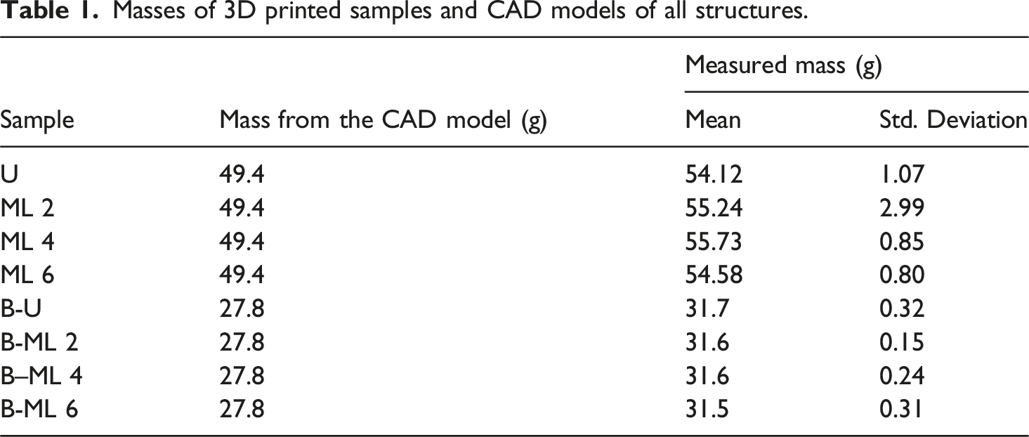
All test samples were fabricated using the material extrusion additive manufacturing process with a Creality Ender-3 S1 Pro and tough nylon filament from Markforged, USA. The material choice of tough nylon is suited to the energy absorption application of this work, ensuring both printability and mechanical performance while remaining faithful to the underlying bio-inspired design principles. Siliceous spicules found in natural sponges are inherently brittle, which makes them unsuitable for engineering applications requiring energy absorption. Flexible or ductile materials (e.g., TPU, elastomers, or stainless steel) enable deformation through bending and rotation rather than fracture, thereby stabilizing the plateau region of stress–strain responses and significantly improving energy absorption. Before fabrication, all CAD models were converted to STL files, and printing parameters were adjusted in the Ultimaker Cura slicer. Notably, an enclosed environment was maintained during printing, and multiple adhesive layers were applied to the build bed to improve adhesion. Six samples of all configurations were printed, out of which three U and ML configurations, and two samples of the B-U and B-ML configurations, which gave consistent analysis results, are reported in this study.
Masses of 3D printed samples and CAD models of all structures.
The U and ML structures were manufactured in the out-of-plane direction (z-direction) and are illustrated in Figure 2. Figure 2(a)-(d) show the uniform and multi-layered compression cubes, while Figure 2(e)-(h) show the uniform and multi-layered beams. Figure 2(e) shows the B-UE with a central empty cell on the top. By flipping this upside down, the B-UF specimen is obtained, with a full cell at the top center. The uniform structure, essentially a 2D design, was printed without difficulty, as no support structures were needed. The wall thickness of the vertical and horizontal members was set to 1.6 mm, while that of the double diagonal reinforcement members was set to 0.8 mm. These values were selected to match the 0.4 mm nozzle diameter, thereby addressing a common challenge in material extrusion printing by minimizing the gap between the designed and printed structures.
28
3D printed samples of all structures – (a) U, (b) ML2, (c) ML4, (d) ML6, (e) B-UE, (f) B-ML2, (g) B-ML4, (h) B-ML6, (i) Dimensions of a unit cell obtained from image and CAD.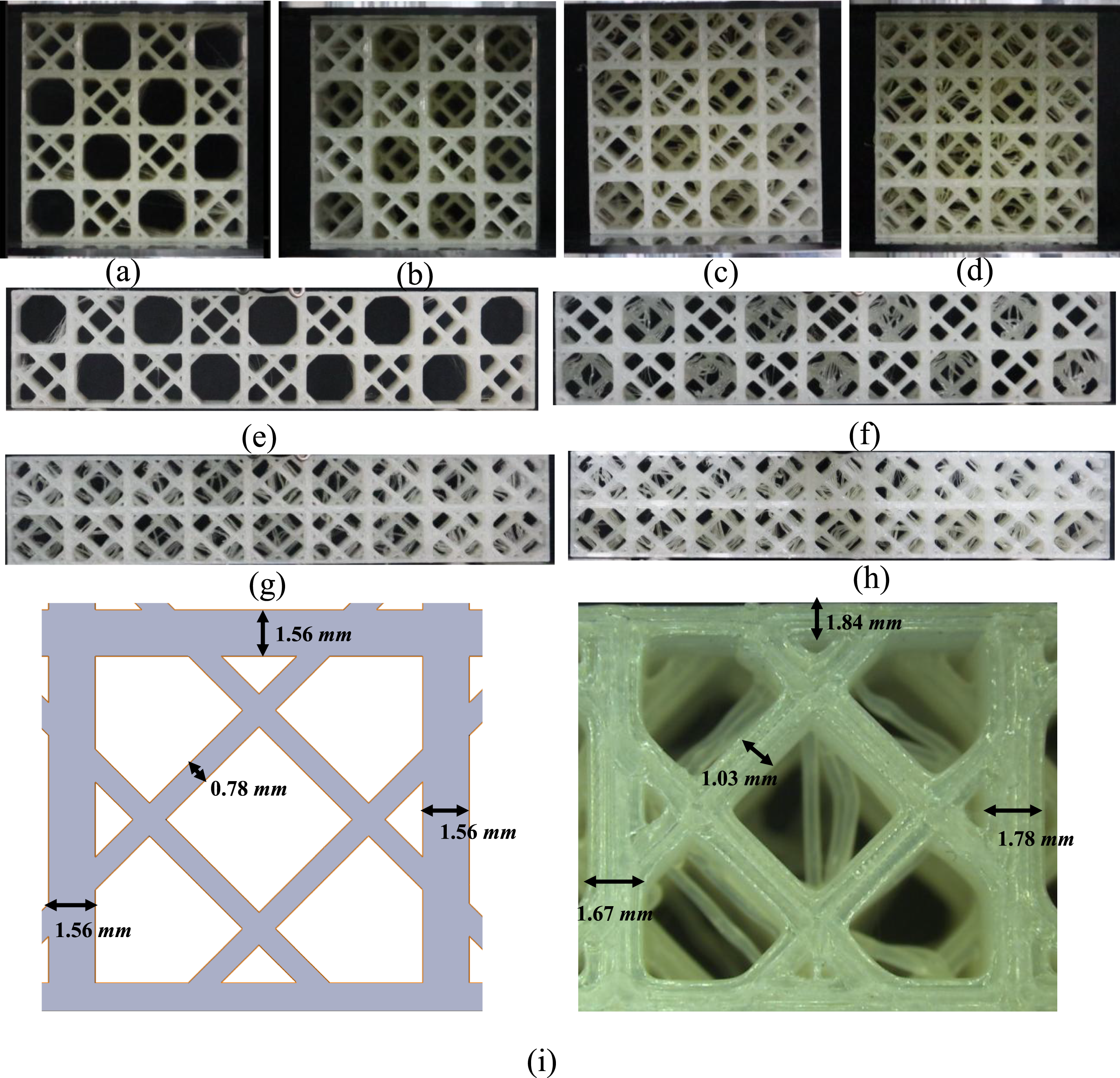
Mechanical testing
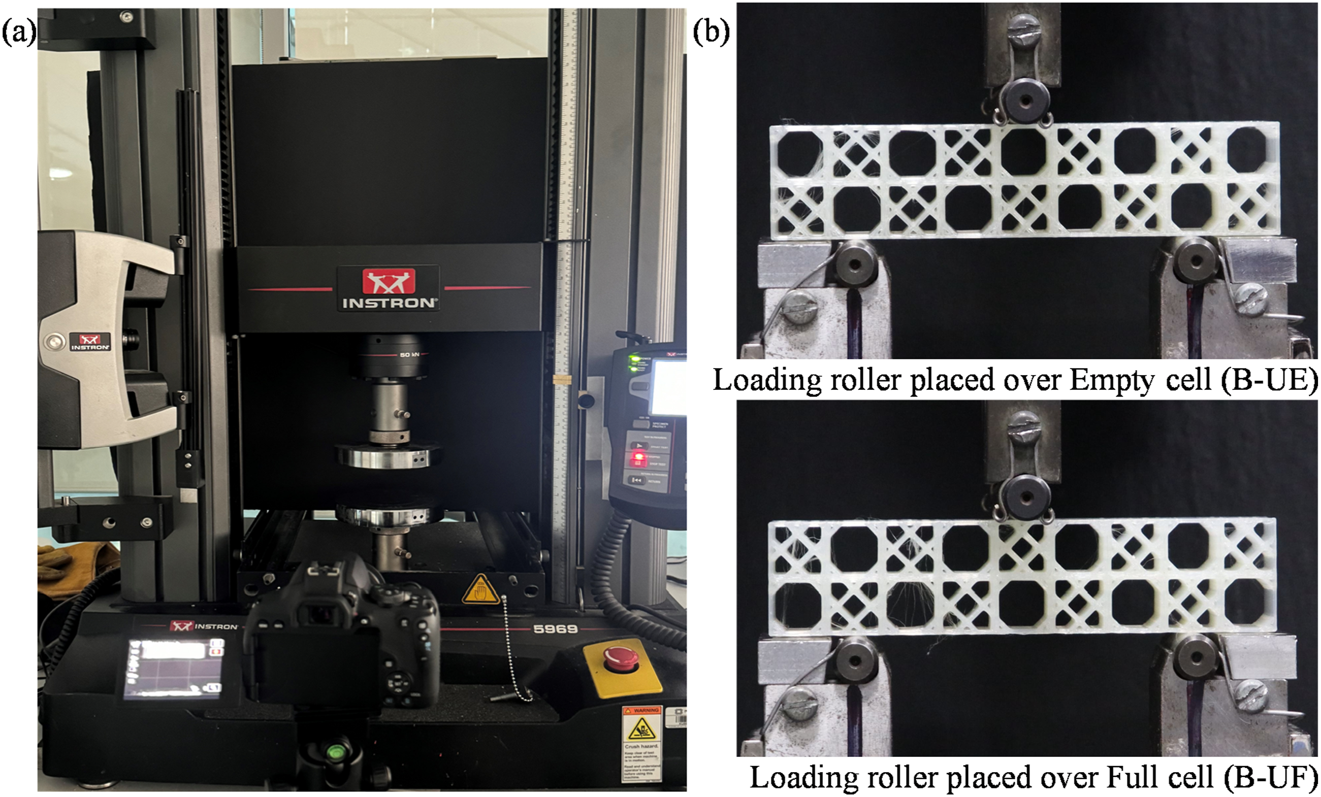
The compression and the flexure tests on lattice structures and tensile test on the solid material were all conducted using an INSTRON 5969 (Figure 3(a)) universal testing machine (UTM) (equipped with a 50 kN load cell, a digital image correlation (DIC) facility and a Digital Single-Lens Reflex camera to record deformation during load application) at a crosshead displacement rate of 2 mm/min. Uniaxial tensile tests were first performed with this UTM on dogbone samples of the nylon material, according to the ASTM D638
29
standard, to evaluate the material’s mechanical properties using strain measurements obtained from the DIC. Quasi-static compression testing was conducted next to evaluate the mechanical properties of the sponge structures under a controlled temperature of 24°C, maintained using an air conditioning system, while the humidity was approximately 40%. Each lattice structure sample was subjected to in-plane compression testing until densification. Three-point bending tests were then conducted on the UTM over a span length of 75 mm to evaluate the flexural strength of the two uniform and three multi-layered structures, with two samples assessed for each configuration. The B-UE and B-UF samples were placed between the rollers, as shown in Figure 3(b), while the B-ML structures were loaded in various orientations, ensuring that both empty and full cells alternated under the central roller in adjacent layers. The mechanical and energy absorption properties were then calculated from the compression tests. The compressive strength and elastic modulus represent the mechanical properties. The compressive strength is the load corresponding to the first peak in the stress-strain curve,30,31 while the elastic modulus is determined by the slope of the elastic region of the stress-strain curve. Energy absorption properties characterized by SEA, densification displacement (DD), and crushing force efficiency (CFE) were also evaluated for all structures. The DD was calculated using the energy-efficiency method, as described in references 32 and 33. This method identifies the DD when energy absorption efficiency reaches its maximum. The energy absorption efficiency can be expressed as: (a) INSTRON 5969 UTM, (b) Placement of uniform beam structures for flexural testing with empty (B-UE) and full cells (B-UF) under the center loading roller.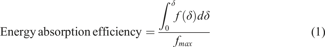
SEA is calculated by dividing the AE by the mass of the structure and can be expressed as:
The CFE, defined as the ratio of the mean crushing force to the peak crushing force, serves as a critical metric for assessing the load uniformity of an energy absorber and can be expressed as:
Results and discussion
The observations from the compression and flexural tests are discussed in this section. The engineering stress-strain curve from the solid material tensile testing is shown in Figure 4. The axial strain was obtained by the INSTRON Advanced Video Extensometer (AVE) coupled with the DIC Replay software. To enable accurate strain tracking, the specimens were first spray-painted with a matte white color and then speckled with black to provide high-contrast patterns. Tensile Test Stress-Strain curve of Nylon material.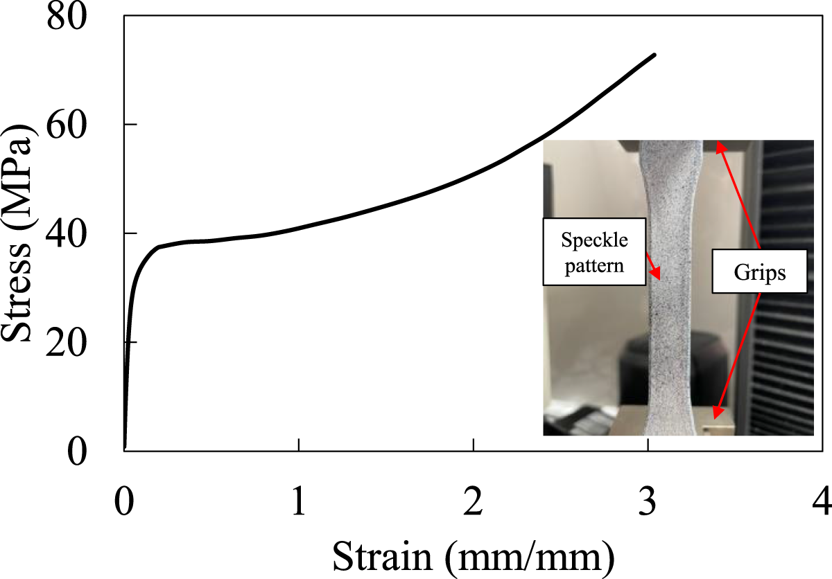
Compression response
Generally, the stress–strain curves obtained from the compression test are divided into elastic, plateau and densification regions. In the elastic region, the applied load is primarily carried by the vertical members. The drop in stress at the yield point occurs due to the buckling of vertical members and bending of horizontal ones. In the plateau region, local buckling of the diagonal members leads to a relatively stable stress response throughout the structure. Finally, during the densification stage, cell walls collapse and come into contact with each other, causing a sharp rise in stress. Among these stages, the plateau region is the longest and most stable, and it is where the majority of energy absorption occurs.
The compressive behavior of all structures reveals that the initial mode of deformation is local buckling of the vertical members, particularly in the empty cells, followed by bending. Figure 5 illustrates the progression of compression for both uniform and multi-layered cubes, and the corresponding f-δ curves of the four structures are shown in Figure 6(a). The shaded region around each curve shows the statistical variation among repeated 3D printed samples of the same configuration, with the bold curve indicating the average response of each structure. Progression of Compression Test on (a) U, (b) ML2, (c) ML4, (d) ML6 at 5 mm, 15 mm and 25 mm displacement compression. The red circles in 5 mm show initial local buckling spots, ovals in 15 mm show compression of open cells that redistribute force to closed cells nearby, and ovals in 25 mm show densification areas. Compression Test Results – (a) Force versus Displacement curve for all structures, note the shading around curve shows the f-δ data of all samples tested with their average curve drawn in bold, (b) Mechanical properties of structures (Young’s modulus and Yield Strength) with ML6 structures showing the highest, Modulus around 50% and strength around 91% more than U (c) Energy absorption properties of structures (SEA) increased by 96% in ML6 from U, (d) Densification strain and effective crushing force similar for all structures.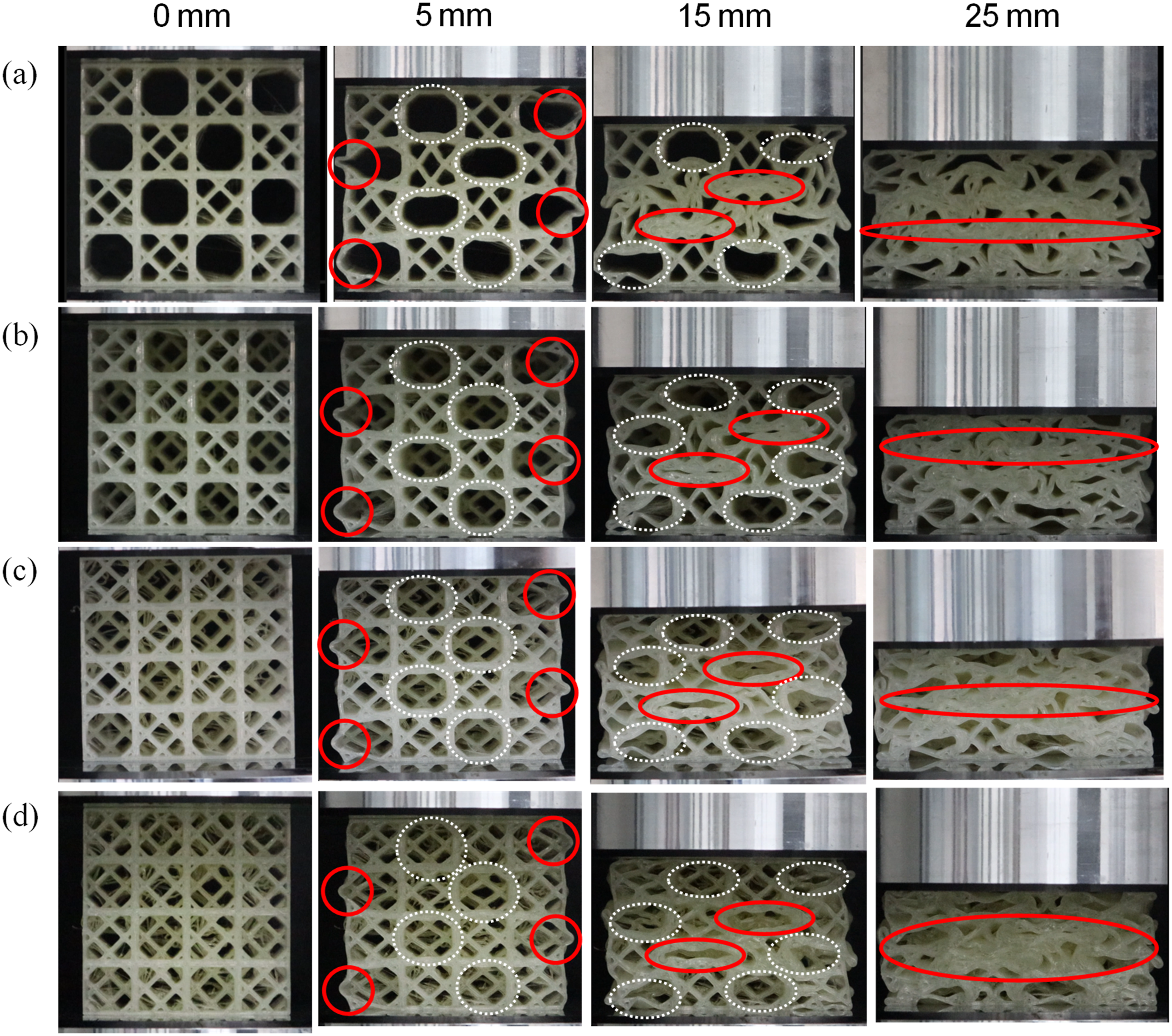
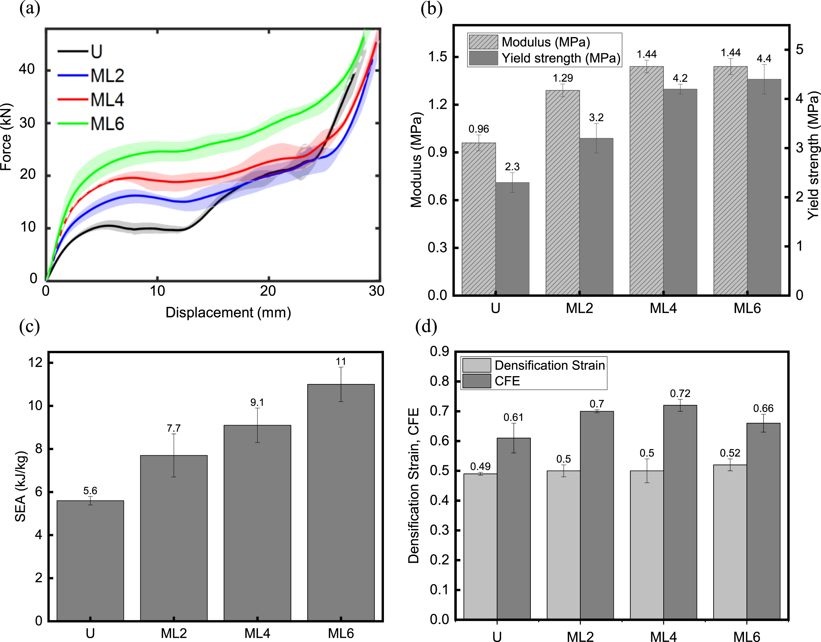
The compression curves of these structures exhibit three distinct regions discussed above: the elastic region up to ∼5 mm displacement, characterized by recoverable deformation; the plateau region extending to ∼25 mm, where most of the energy absorption occurs; and the densification stage begins at ∼28 mm displacement, beyond which the stress increases rapidly. The f-δ curves for all structures initially rise to a peak, reflecting resistance to deformation. All the structures exhibited a gradual rise in force up to the critical buckling load, suggesting that deformation was governed by local buckling and bending before the structures reached their critical buckling point, as highlighted by the circled regions at 5 mm displacement in Figure 5. Following the critical buckling load (compressive strength), the curve enters a plateau phase, maintaining a relatively stable force level of around 10-25 kN. No pronounced post-peak drop was observed, suggesting that the structures maintain their strength throughout this region. This plateau, extending from a displacement of ∼8 mm to 25 mm, reflects a complex interaction within the structures, including the reorientation of members, redistribution of force between the open cells and closed cells, as shown by ovals at the 15 mm displacement in Figure 5. This redistribution enables deformation without a corresponding increase in force.
With further loading, localized densification initiated along the empty cells, leading to fluctuations. All the cell walls collapsed during the densification stage, resulting in an increase in stress. Beyond 25 mm, the curves rise again, marking the onset of the densification phase. All structures failed by local buckling and bending. In the uniform structures, the vertical members of the unreinforced edge cells exhibited pronounced local buckling (highlighted by red circles at 5 mm displacement in Figure 5), whereas the layered structures showed reduced buckling in the same regions. Similarly, the unreinforced central cells (indicated by dashed white ovals) in the uniform beams deformed more severely than those in the layered counterparts. Increasing the number of layers further suppressed this distortion; in the ML6 structure, for example, neither the double diagonally reinforced cells nor the unreinforced cells in the first layer showed noticeable distortion. This behavior can be attributed to the interaction between unreinforced cells and the adjacent diagonally reinforced cells behind them, which enhances their load-bearing capacity. At 15 mm displacement, in the uniform designs, only a limited number of unreinforced cells remained stable (indicated by the dashed white ovals), whereas in the layered structures, the interaction with adjacent diagonally reinforced cells distributed the load more uniformly. This interaction effect prevented collapse in a greater number of unreinforced cells, thereby enhancing the overall stability of the layered lattices.
All the mechanical and energy absorption properties are derived from this f-δ curve according to Equations(1)-(4) and from integration for DD. The multi-layered structures exhibited higher compressive strength because alternating empty (E) and double-diagonally reinforced (F) cells across layers created through-thickness interaction. When vertical members in an E layer began to buckle, the adjacent F cells in neighboring layers provided lateral restraint and redistributed the load, preventing premature collapse. This interaction, combined with strut reorientation and force redistribution between E and F cells, increased the peak load and enhanced stiffness. As the number of layers increased, these stabilizing effects became more pronounced, with the ML6 structure achieving the highest compressive strength and Young’s modulus (Figure 6(b)), despite all configurations having identical relative density. The area under the f-δ curve, representing the energy absorption capacity, was greatest for the ML6 structure. This resulted from its elevated plateau load, sustained by the increased interactions arising from the greater number of layers and their interfaces between empty and reinforced cells, which yielded the highest specific energy absorption (SEA) (Figure 6(c)).
For an ideal energy absorber, the difference between peak force and mean plateau force should be minimal, a criterion satisfied by all the multi-layered architectures. By contrast, the uniform structure exhibited a sudden load increase at ∼12 mm displacement due to the simultaneous collapse of all E cells, which raised the mean plateau force above the peak force. The presence of adjacent F cells in the layered designs prevented this instability, enabling a sustained and stable plateau response relative to the peak force. Additionally, the densification strain of all multi-layered structures was comparable to that of the U structure, while the CFE of ML6 was relatively lower than that of ML2 and ML4, although all multi-layered structures outperformed the uniform design (Figure 6(d)). This reduction in ML6 can be attributed to its more pronounced post-yield hardening effect, driven by greater interactions, whereas the other layered structures exhibited a more stable plateau following yielding.
Adopting the multi-layering approach led to remarkable performance gains, with the lattices exhibiting up to ∼50% higher stiffness, 138% greater compressive strength, and nearly double (96% higher) energy absorption compared to the uniform deep-sea sponge architecture (U).
Figure 7 shows an Ashby plot comparing the SEA of different multi-layered structures. The axes are shown on a logarithmic scale, and each dot represents the SEA of a structure from one of the categories of Square, hexagonal, and re-entrant honeycomb structures,
23
along with a deep-sea sponge structure reported in the literature,
7
compared against multi-layered deep-sea sponge designs of the present work. The ML6 structure shows the highest SEA among all layered structures, even when compared with the square honeycomb structure of higher relative density. This demonstrates that lightweight layered structures with high SEA can be achieved using the deep-sea sponge architecture. Gibson-Ashby plot for multi-layered designs of square, hexagonal, and re-entrant honeycomb structures
23
and a benchmark deep-sea structure from literature similar to our uniform deep-sea structure geometry, compared with the multi-layered deep-sea sponge structures of the current study. Note how the current study, specifically ML6 exhibits the highest SEA, even greater than the Square honeycomb of higher relative density.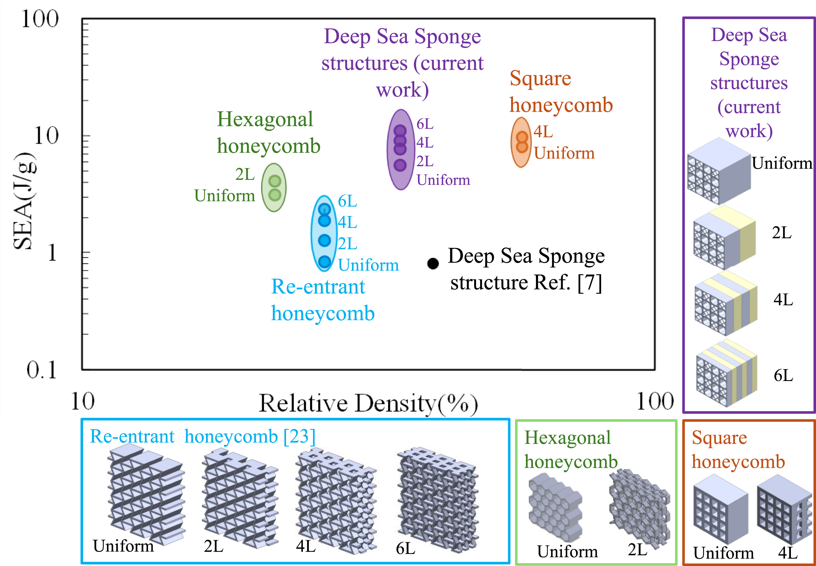
Flexural response
The bending resistance of both uniform and multi-layered beam structures was evaluated using three-point bending tests. The progressive stages of deformation are shown in Figure 8, while the corresponding force-displacement (f-δ) curves are presented in Figure 9. Flexural behavior of beams under 3-point bending test for sample S1 of (a) B-UE, (b) B-UF (c) B-ML2, (d) B-ML4 and (e) B-ML6 samples at 6 mm, 15 mm, and 26 mm displacement. Bending Test Results – Force versus Displacement curve for all structures and local buckling (marked in red circles) of (a) B-UE, (b) B-UF (c) B-ML2, (d) B-ML4 and (e) B-ML6 at 6 mm displacement after the critical buckling point.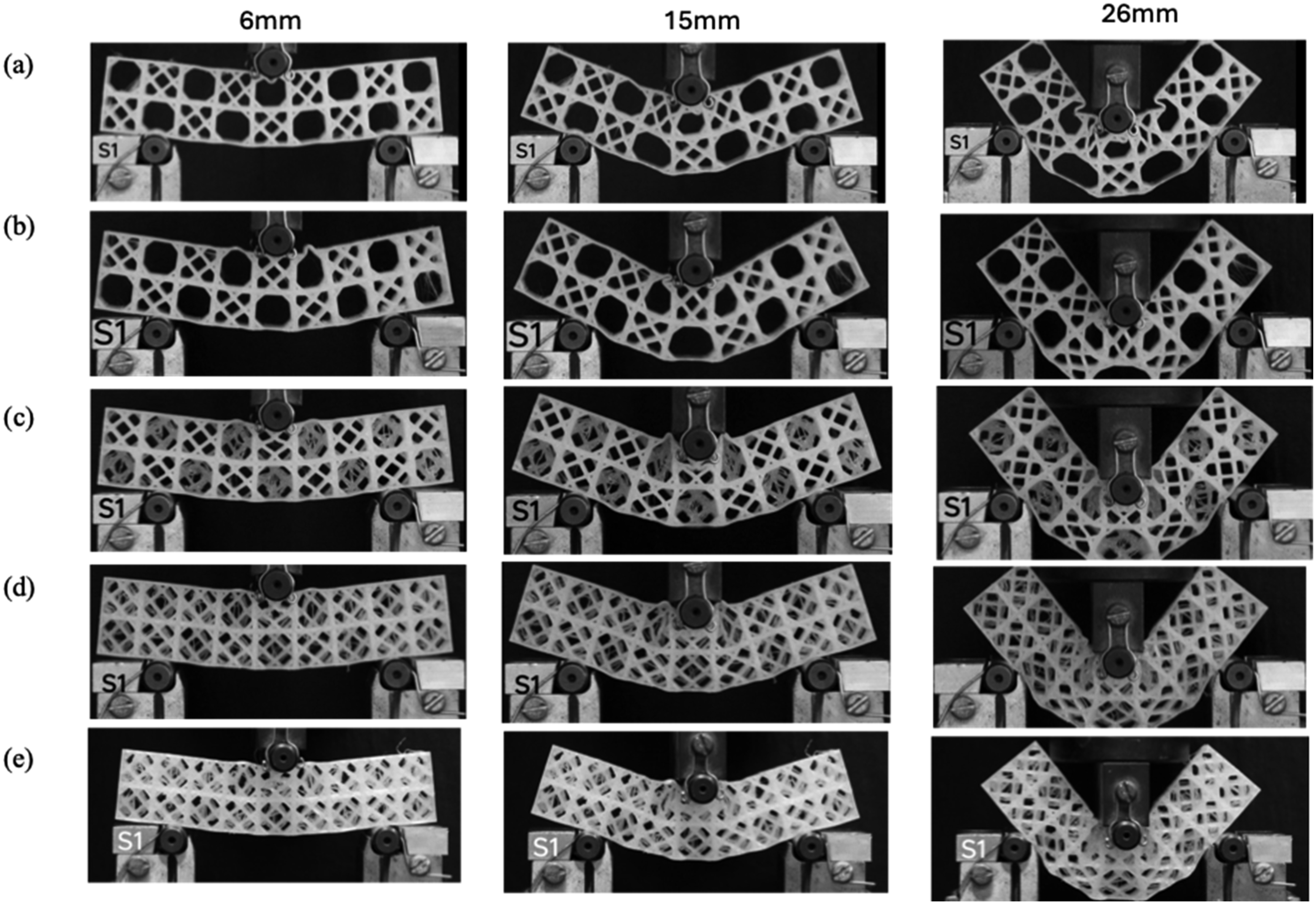
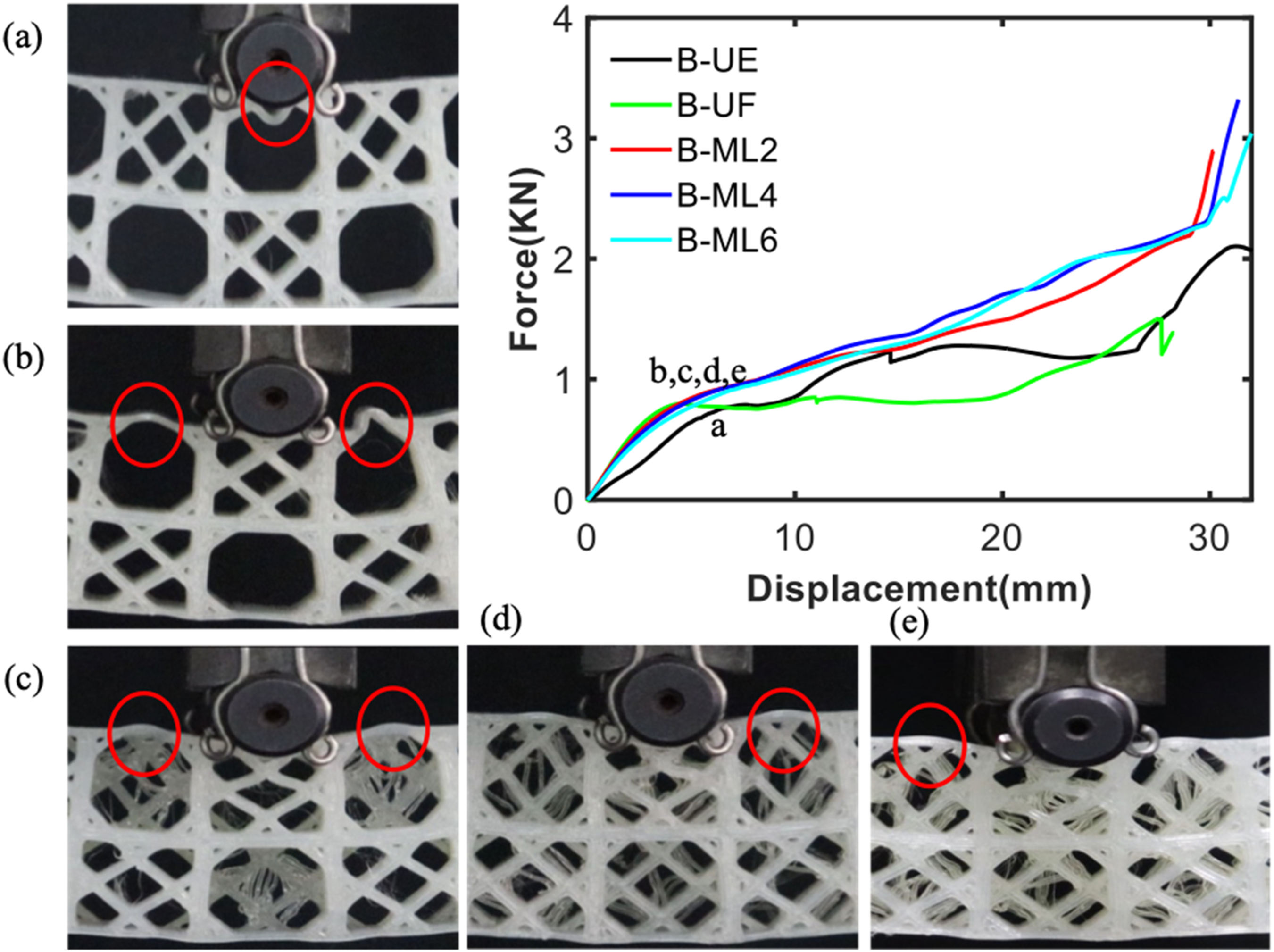
All multi-layered structures demonstrated superior bending resistance compared to the uniform ones. Among the uniform beams, the B-UE exhibited better flexural strength than B-UF, despite its lower flexural rigidity. This behavior is attributed to the structures’ load-transfer mechanisms. In the B-UE structure, the empty cell directly under the roller, located in the region of maximum compressive stress during bending, undergoes local deformation, as highlighted in red in Figure 9(a). The adjacent full cells resist the load transferred from this empty cell, while the full cell located immediately below the central empty cell carries the highest tensile load and transfers it to the neighboring empty cells on either side. As bending progresses, the two full cells on either side effectively resist the load, transferring it in an inverted triangular pattern to the central full cell, which produces a long plateau in the f-δ curve. However, the two empty cells adjacent to the central full cell are unable to sustain the tension load transferred from the top empty cell, leading to lower bending stiffness. The experiment was terminated when the top edges of the beam touched the bending apparatus. At around 35 mm displacement, the bottom empty cells adjacent to the central full cell experienced maximum tensile stresses, leading to the loss of their load-bearing capacity.
In the B-UF beam (Figure 9(b)), the central full cell flanked by empty cells does not effectively transfer the applied load, leading to local buckling in both adjacent empty cells. With further loading, the lower central empty cell, which experienced the highest tensile load, failed at about 26 mm displacement. This issue does not occur in multi-layered structures, as the alternating full and empty cells in different layers interact to transfer the load more effectively. Therefore, local buckling, shown in Figures 9(c)–9(e), is negligible, with B-ML6 exhibiting the greatest resistance to local buckling. The bending tests also demonstrate that multi-layered structures improve flexural resistance by approximately 25% compared to uniform structures.
The flexural and compressive responses provide critical insights into the performance of lattice structures as sandwich cores, as their dominant failure modes are crushing and buckling under these loading conditions. Flexure tests are a standard method for evaluating the energy absorption performance of sandwich structures, as they induce core-level failure modes (shear, crushing) that are critical for energy dissipation in bending-dominated applications. 34 However, extending these experimental findings to model periodic lattices requires the use of simulations with periodic boundary conditions to accurately capture their behavior as sandwich cores. This constitutes a key objective for future work.
Conclusion
This paper presents a comprehensive investigation into the compression and flexural behavior of multi-layered lattice core structures inspired by the skeletal system of the deep-sea sponge, Euplectella aspergillum, an organism renowned for its naturally optimized mechanical performance. Specifically, we design and fabricate uniform structures alongside two-, four-, and six-layered lattices composed of periodic sponge-inspired unit cells, enabling a systematic comparison of their structural performance. While prior research has established the exceptional strength and toughness of Euplectella-inspired architectures, this study is the first to extend the concept to multi-layered configurations, drawing inspiration from similar layering strategies in other lattice systems that have demonstrated enhanced in-plane performance under mechanical loading. Through rigorous quasi-static compression and three-point flexural testing, the multi-layered designs revealed remarkable improvements in mechanical properties, with Young’s modulus, compressive strength, and specific energy absorption enhanced by up to 50%, 138%, and 96%, respectively, when compared with uniform counterparts of equal relative density and weight. Notably, Ashby plots demonstrate that the newly developed sponge-inspired lattices exhibit the highest specific energy absorption among all known layered structures, including those of significantly higher densities, underscoring the efficiency and superiority of the bio-inspired multi-layering approach.
These findings provide conclusive evidence that layering strategies can substantially elevate the mechanical performance of deep-sea sponge-inspired lattices, establishing a new benchmark for lightweight, high-performance structural materials. Beyond their immediate experimental significance, the results open up transformative opportunities for the design and development of advanced sandwich lattice architectures with precisely tailored properties to meet demanding requirements in aerospace, defense, automotive, and energy-absorbing systems. The specific applications where lightweight energy absorbers are required include crash absorption zones of automotive, aerospace, and space vehicles; shock absorbers of aircraft landing gears; impact protection against meteoroids and orbital debris in spacecrafts; vibration dampers in aircraft, to name a few. This study not only validates the untapped potential of Euplectella-inspired designs but also positions multi-layered bio-inspired lattices and sandwich lattice cores as a paradigm shift in the field of architected materials.
Footnotes
Author contributions
I.Z.: Conceptualization, Methodology, Data curation, Software, Validation, Formal analysis, Investigation, Writing—original draft. A.V.: Methodology, Data curation, Software, Formal analysis, Writing Original Draft. K.A.K.: Conceptualization, Methodology, Writing—review & editing, Visualization, Resources, Investigation, Supervision, Project administration, Funding acquisition.
Funding
The authors disclosed receipt of the following financial support for the research, authorship, and/or publication of this article: This work is funded by Sanad Aerotech and supported by the Advanced Research and Innovation Center (ARIC), which is jointly funded by Aerospace Holding Company LLC, a wholly-owned subsidiary of Mubadala Investment Company PJSC and Khalifa University for Science and Technology.
Declaration of conflicting interests
The authors declare that they have no known competing financial interests or personal relationships that could have appeared to influence the work reported in this paper.