
Abstract
Paper-based materials are being alternative candidates to build load-bearing components for the high demanding building sector to be committed to the green transition, but more knowledge of structural mechanics of such components is needed. In this work, three categories of innovative load-bearing sandwich beams with cup-box core fully made of different paper materials were produced, tested and analyzed in four-point bending. The first failure mode was observed at the top facesheets due to the low compressive strength of paper materials; Beams with thin facesheets had premature buckling failure, whereas those with thicker facesheets exhibited ductility reaching higher deflection before the compressive failure. The developed finite element model, calibrated with the experiments for the equivalent bending and shear rigidities, provided figures of the modulus of the facesheet as well as the properties of the core. Furthermore, the compressive plasticity behavior of the facesheets was assessed by fitting the model with load-deflection curves from the tests. Using the model for the structural optimization of the thickness and height of the core, the work suggests optimal values 3 times higher than the original ones.
Introduction
One of the immediate initiatives globally adopted to tackle the global warming is the implementations of green economy policies, 1 which are linked to the sustainable development goals. 2 The implementations are complex and affects different levels in the society, but the notion has already been started, especially the transition towards the use of renewable products over fossil-based counterparts. Now, an increasing number of products and materials derived from trees are replacing fossil-based alternatives. Typically, around 25% of a harvested tree becomes timber and the remaining large portion becomes pulp-based products, which is the basis for the major contribution of the packaging industries to the development of the pulp and paper sector over the years. These advancements have led to sophisticated manufacturing processes, such as the molded pulp process for the development of molded food packages and similar products. 3 It has been a great step forward because complex geometries made of wood fibers could then be achieved. The processes are versatile and allow to incorporate recycled fibers as well. However, mechanical properties of paper materials are affected by any adjustment in the processes. In the literature, mechanical properties of papers made of different processes have been vastly studied in different aspects. 4 As a brief review, those aspects are, but not limited to, anisotropy properties,5–7 the process-property relations, 8 asymmetry of strength in tension and compression9,10 fracture mechanical properties of paper materials,11,12 moisture dependency for stiffness and strength13–15 and creep properties of papers.16–18 Even finite element (FE) models from converting processes to food packages was developed 19 as well as FE simulations to predict the mechanical performance of entire food packages. 20 The knowledge of the mechanics of paper materials is substantial and have now reached a good level of maturity for reliably design food packages from the material level to final products at least for short-lived end-uses.
Other sectors are also exploring the possibility to finetune mechanical properties of paper materials for different long-lived applications. In Sweden, the company WoodTube recently launched a patented hollow stud made of paperboard for partition walls. 21 This initiative opens the door to a new research area to be explored. It also means that the well-stablished knowledge from packaging community should carefully be transferred to the research field of building technology. One challenge in this knowledge transfer is that paperboards are thin materials and structural components are relatively larger than food packages. To make larger structural members out of thin materials, one alternative is through sandwich structures with lightweight cores.22–24 The cores of such structures can be designed in different shapes - from traditional honeycomb shapes 25 to peculiar cup-box shapes 26 - to adapt different loading conditions. 27 Typically, in building applications, paper-based sandwich structures are commonly made of honeycomb core with hexagonal shape and are primarily evaluated by bending loading cases.28,29 They are intended to furniture and interior applications, aiming to create lighter furniture to reduce health issues from lifting and moving and saving from furniture transportations costs. 30 For the construction segment, such structures have been used as building envelops and cladding systems. 31 Mechanically, honeycomb cores have higher stiffness perpendicular to the facesheets, greater shear stiffness, and better strength-to-weight ratios compared to other available core shapes.32,33 However, their manufacturing processes are not trivial and consist of multiple steps (e.g., expansion processes where thin corrugated sheets are manufactured, glued, stacked, cured, etc.), which may lead to some practical difficulties during assembling of the core. Despite such difficulties, paper honeycomb sandwich structures have demonstrated appealing indicators of mechanical performance per cost offering economic advantages for furniture producers. 34
Thanks to continuous improvement of molded pulp processes, complex-shaped cores made of paper materials can now be manufactured and studied.
35
It also allows for the production of paper cores in large volumes and more efficiently than expansion processes. In that direction, some other companies in Sweden have developed an innovative sandwich structural element fully made of paper materials for indoor products, such as tables, shelves, doors, and furniture in general.
36
The element, lightweight and stronger, has facesheets of high-strength laminated paperboards made of recyclable and/or virgin wood fibers. The core made of the molded pulp process has a shape like a cup-box (c.f. Figure 1(b)), which can be seen as a variant of the honeycomb core adapted to the new manufacturing process. The main inevitable shape changes include introduction of angles, closing cells and removing sharp corners (round cells) for facilitating the extraction of the core from the mould. (a) Photographs of the facesheets A, B and C and of (b) a unit of cup-box core showing its shape with dimensions. (c) Micrographs showing the cross section of the facesheets as well as showing in-plane random fiber orientations of the cup-box core.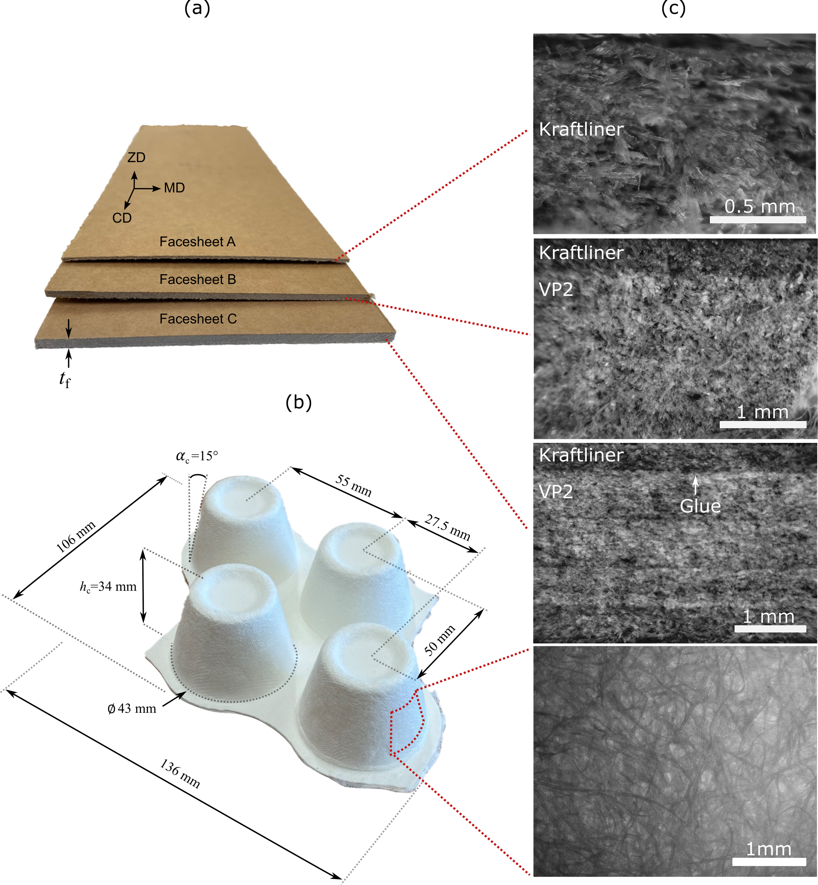
The development of the paper sandwich structural element clearly indicates the increasingly interest for developing structural components made of paper materials for the building sector suitable for mass production, but the mechanical performance of the innovative design of the elements has not been examined by any means. In general, there is obviously a gap in documentation regarding mechanical performance of paper materials in structural-scale products,31,33 especially those made from mould pulp processes as a nearly developed process compared to other traditional ones. To address this lack of knowledge and evaluate the structural performance of the novel paper sandwich element, the present work aims to study beams from the paper-based sandwich element under bending. This approach not only contributes to filling the existing knowledge gap but also introduces novel paper-based materials in structural engineering applications.
The primary objective of this study is to investigate the bending performance of sandwich beams made of high-strength laminated paperboard facesheets (Smurfit Kappa Sverige AB, Sweden) and Greenwood™ cup-box cores (Ecopals AB and Rottneros Packaging AB, Sweden) under four-point bending conditions. This investigation entailed both an experimental test series coupled with digital image correlation (DIC) and the development of a parametric FE model. The predictions of the model were evaluated against the results obtained from the experimental tests. An important objective of the study was to determine the flexural and shear rigidities of the samples from both experiments and FE modelling. Furthermore, the study included a concise parametric analysis aimed at identifying the optimal geometry of the core of the beam under bending conditions. By combining experimental data and FE simulations, the research provides increased understanding of the bending behavior of these innovative sandwich beams.
Materials and methods
Sandwich beams
Facesheet and core materials
The sandwich beams studied were assembled with two facesheets, one at the top and one at the bottom, and one type of core arranged in several units along the beams. The core used was the same for all test specimens while the thickness and orientation of the facesheets varied. The materials for the facesheets, see Figure 1(a), were provided by the company Smurfit Kappa Sverige AB in three configurations: (A) Single-ply laminate made from 75% virgin fibers from Northern Sweden and 25% recycled fibers from corrugated board (Kraftliner Brown, Smurfit Kappa, Sweden) with a total thickness tf = 1.1 mm and the density ρ = 816 kg/m3, (B) hybrid three-ply laminate with a total thickness tf = 2.3 mm and the density ρ = 741 kg/m3 having two 0.5-mm-ply of Kraftliner Brown at the faces and a 99.5%-recycled-fibers ply in the middle (VP2, Smurfit Kappa, Germany), and (C) hybrid three-ply laminate with a total thickness tf = 2.8 mm and the density ρ = 768 kg/m3 having two 0.5-mm-ply Kraftliner Brown at the faces and a VP2 ply in the middle. This laminate is thicker than B because a water-based glue was added between plies. Then, the laminate was pressed between two rollers in the process. The purpose of the glue is for improving the moisture resistance in a sense of final product application.
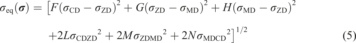
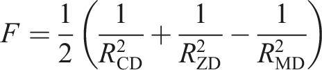
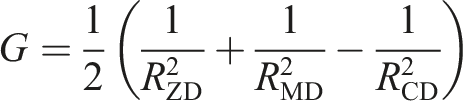
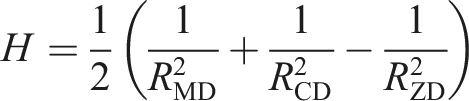
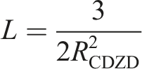
The facesheets were manufactured by chemi-thermomechanical pulping (CTMP). 37 In the production process of such facesheets, the material becomes orthotropic with three orthogonal material directions. The machine direction (MD) is the direction parallel to the production line, the perpendicular in plane direction is referred to as the cross direction (CD), and the out of plane direction is the Z-direction (ZD). The material coordinate system is exemplified in Figure 1(a) for facesheet A.
The Greenwood core units were manufactured by molded pulp process by Rottneros Packaging AB and contained only virgin fibers. Each unit includes four tapered cups arranged in staggered positions and all connected at the base. Figure 1(b) shows a core unit with its respective dimensions. The unit has a nominal thickness of tc = 0.8 mm.
Assembly of the sandwich beams
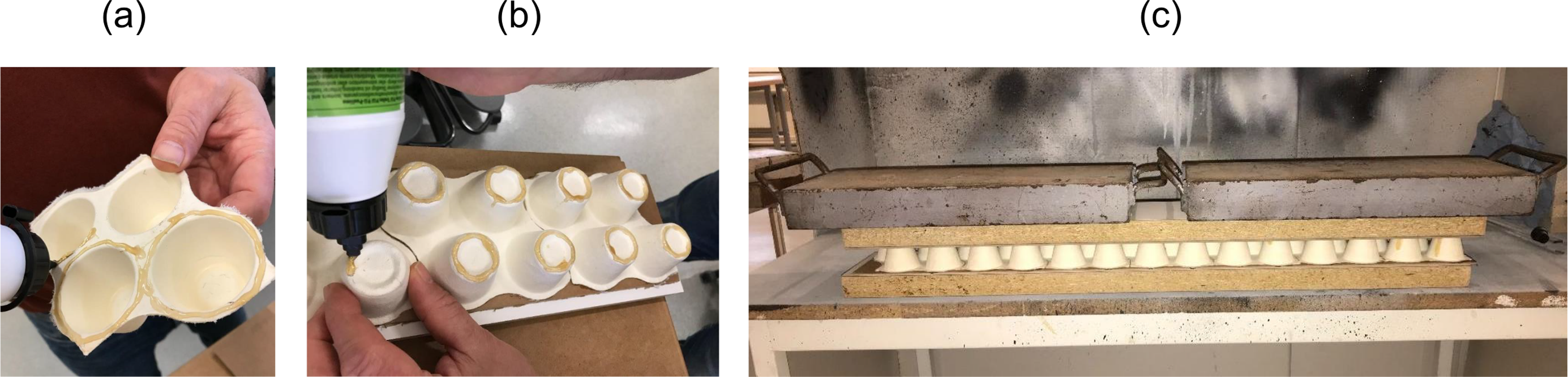
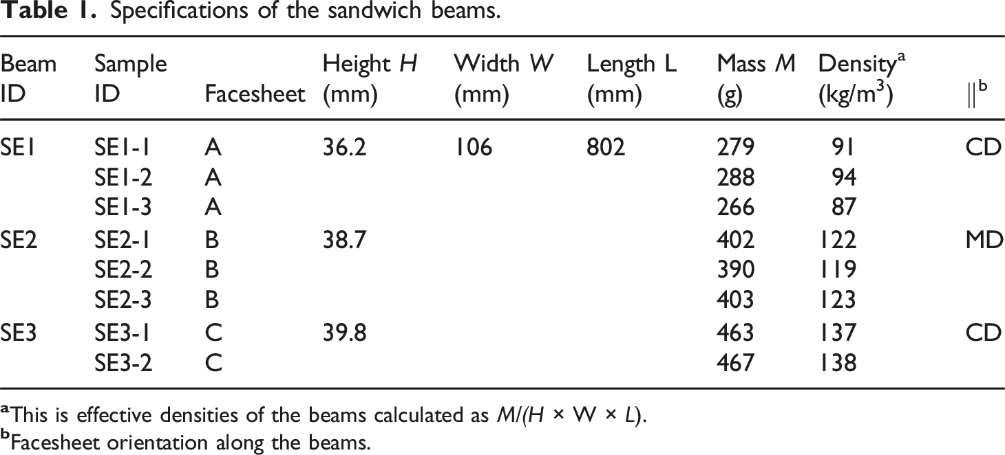
The facesheets were cut with a bench circular saw (Proxxon, Germany) in rectangular dimensions of 802 × 106 mm2 to accommodate seven cup-box core units in the length direction and one in the width. Figure 2 shows the process of assembling the elements: (a) a solvent-free polyurethane adhesive for wood (Illbruck, Sweden) was applied in the bottom of the core units to be glued to the bottom facesheet, (b) the adhesive was then applied at the top of the attached core units. Thereafter the top facesheet was attached and (c) the beams were loaded with 500 N self-load distributed over the top surface for curing during 5 h. In total, eight sandwich beams samples were prepared and categorized in three groups according to their facesheet materials. An important detail for the production of the beams was the orientation of the facesheets. For SE1 and SE3 beams, the facesheets were glued so that the cross direction (CD) was parallel to the length direction of the beam. For the SE2 beams, the machine direction was in parallel to the length direction of the beam. A full specification for each sample is provided in Table 1. Process of assembly of the beams: (a) applying adhesive at the bottom of the core units, (b) attaching the core units to the bottom facesheet and applying adhesive on top and (c) pressing the assembly for curing. Specifications of the sandwich beams.
Four-point bending tests
A standard four-point bending test often utilised for investigating stiffness and strength of beams was used to investigate the properties of the eight beams in the study. Before carrying out the bending tests, nine flat-head push pins were glued with a hot-melt adhesive along the top and bottom facesheets at every d = 67.5 mm, see Figure 3(a). 3-mm white point markers (GOM, Germany) were attached to the pin heads as references for measuring the beam deflection during loading by means of Digital Image Correlation. Figure 3(b) shows the final beam construction installed in the four-point bending rig. The supports as well as the loading points consisted of steel rollers, each supported at their center with pin connections to allow for rotation and horizontal displacement. The loading points were connected to a spreader beam and further to the load cell via a hinge. Steel plates with dimensions 150 × 50 × 5 mm3 were inserted between rollers and specimens to reduce stresses and minimize local damage of the face sheets caused by the rollers. The dimensions of the setup are illustrated in Figure 3(c) where the loading span a = 225 mm, the total span for bending the beam is 3a = 675 mm and the total length of the beam is L = 802 mm. The span to depth ratio 3a/H of approximately 18 was chosen to ensure a reasonable relation between deformation due to pure bending and shear. The tests were performed in a bending testing machine (MEGA 6-3000-200, Form + test Prüfsysteme, Germany) with an external 10 kN load cell and displacement control mode with a loading rate of 3 mm/min. During the tests, a stereo-camera system (Aramis 12M, GOM, Germany) was used to measure the displacements at the attached markers by DIC. The system configuration was set as measuring distance of 700 mm, camera angle of 25°, and slider distance of 291 mm. The test climate condition was relative humidity of 38 % and temperature of 20°C. (a) Gluing the push pins in the facesheets, (b) photograph of the four-point bending setup, and (c) illustration of the undeformed and deformed configurations with dimensions.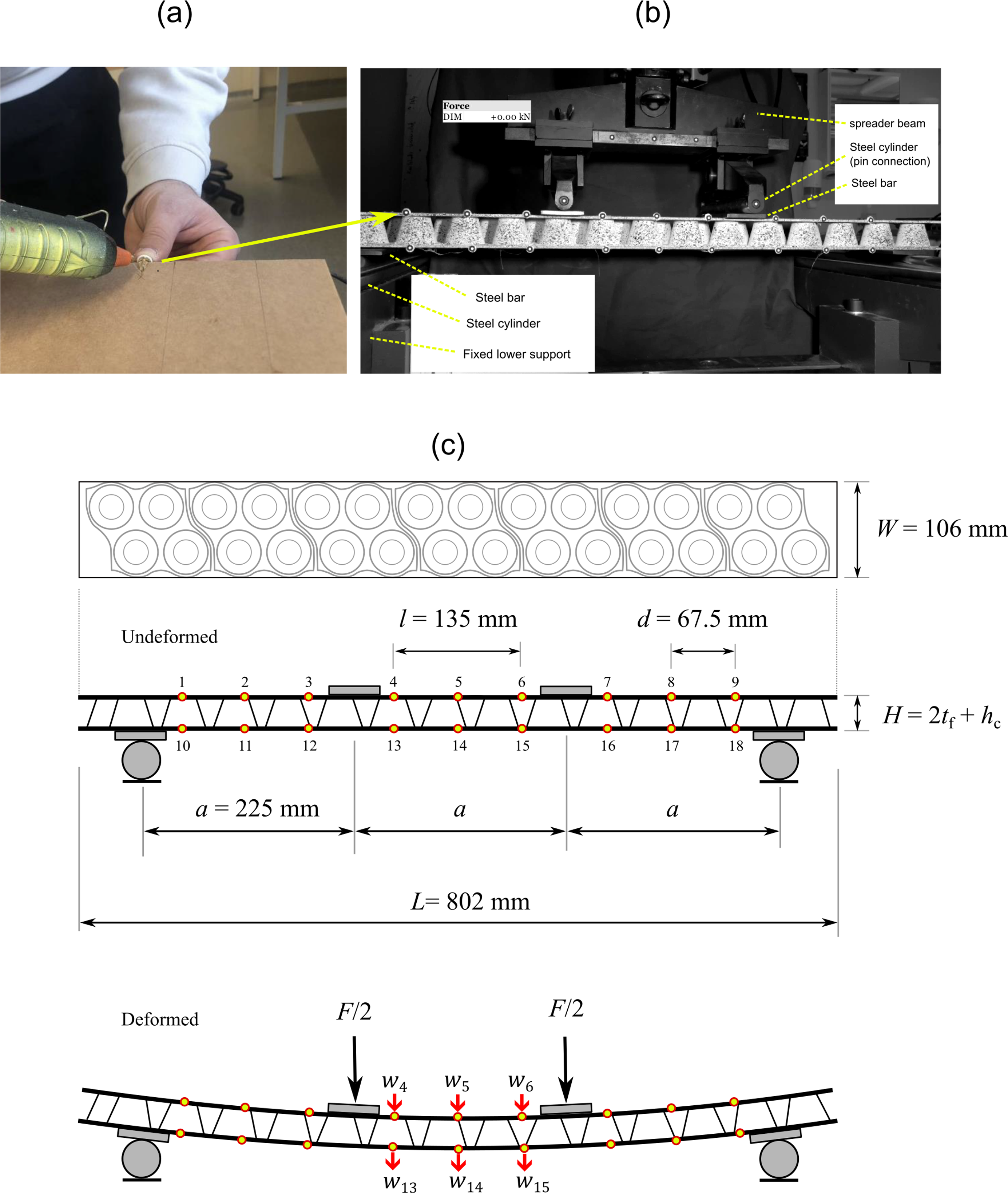
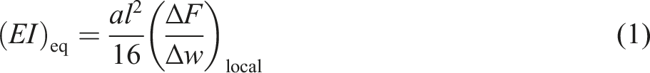
The equivalent flexural rigidity is calculated from the markers at the mid-span (shear-free) for four-point bending as
38
The equivalent shear rigidity is approximately calculated as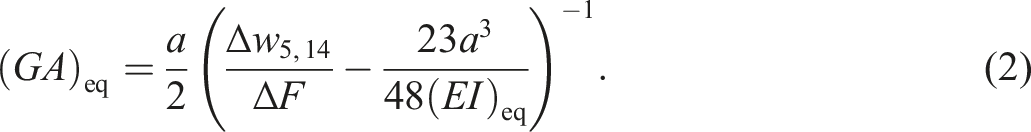
Equation (2) is also evaluated at both facesheets. The first term in the parenthesis is the ratio between the mid deflections
FE model of the sandwich beams
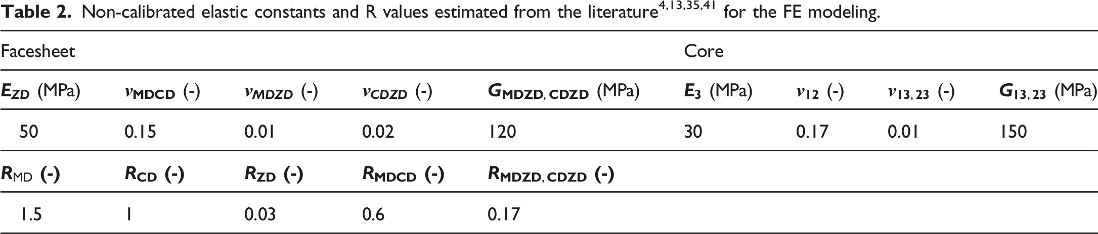
A flexible finite element model was developed primarily to simulate stiffness and strength of paper-based beams similar to those in the experimental tests, but with different heights, material properties and material thicknesses. A parametric model was developed in the FE software Abaqus. Boundary conditions such as displacements FE model: (a) geometry, boundary conditions and (b) meshing. The 1-2-3 coordinate systems indicate the material orientation for the facesheets (blue) and the core (red).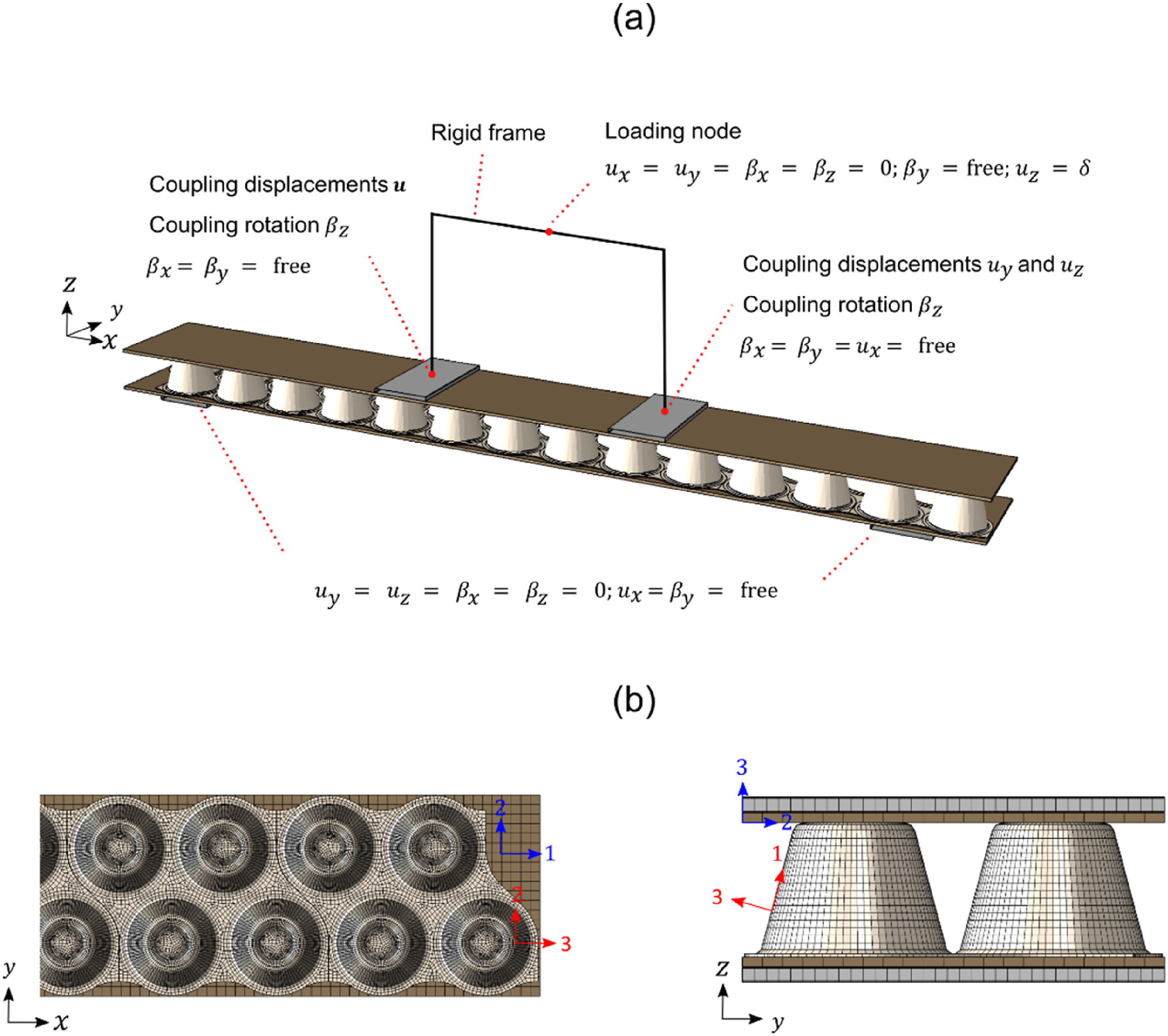
The 1-2-3 coordinate systems in Figure 4(b) indicate the local material orientations. The core is modelled assuming in-plane isotropic linear elastic material, so called transverse isotropic material. During bending, the facesheets at the bottom are subjected to tension while the facesheets at the top are compressed. As paper-based materials typically have lower strength in compression compared to tension,for example, 10 this must be considered to be able to capture the first failure mode in the FE simulations.


Results and discussion
FE model calibration
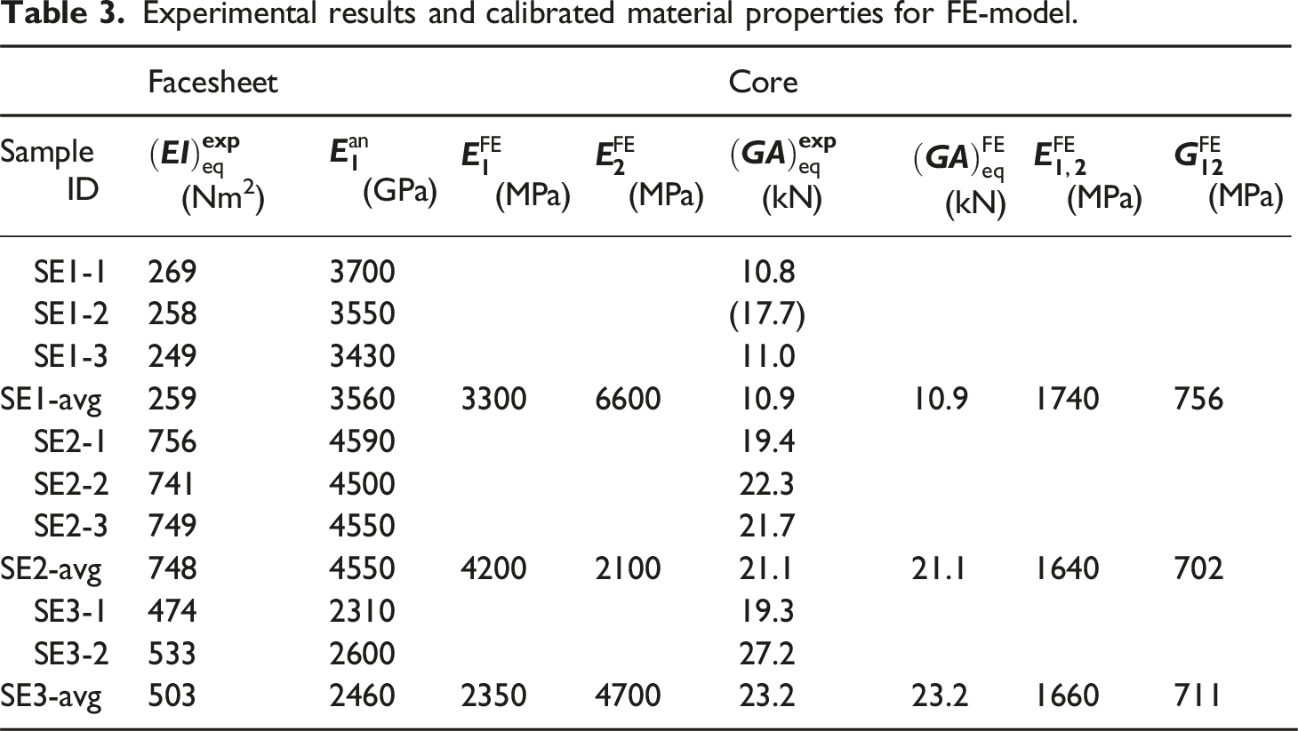
Experimental results and calibrated material properties for FE-model.
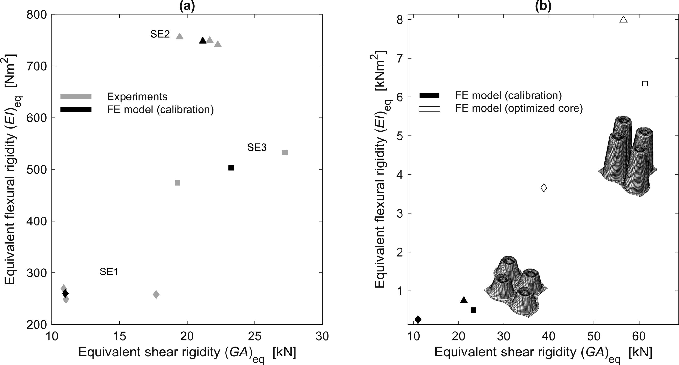
Experiments and FE results of flexural and shear rigidities for SE1 (diamonds), SE2 (triangles) and SE3 (squares): (a) calibrated values from FE models over rigidities of all experiments and (b) the calibrated rigidities values over the rigidities with optimal core geometry from the optimization studies.
The main purpose for cores in bending is their shear properties. By averaging out the equivalent shear rigidity of cup-box core in Tables 2, it becomes
Load-displacement relations
Figure 6 shows the force-deflection curves at mid-span at the bottom and top facesheets for both experiments and simulations. As shown in the experiments, SE1 beams had a short plasticity range before the sudden drop in force level, while SE2 and SE3 developed significant plastic deflection before the drop in force, indicating a more ductile behavior. The failure in SE1 was caused by local buckling of the thin compressed top facesheets for all three tested specimens. The buckling was observed in the constant moment region in the vicinity of one of the two loading points. The failure was initiate due to compression yielding in intermittent regions of the facesheets without support of the core and, subsequently, buckling behavior occurred due to the thin thickness of the facesheets. The buckling behaviour was diagonal following the staggered pattern of the cups in the core, see Figure 8. Force-deflection diagrams for all eight test samples along with results from FE simulations of each beam configuration.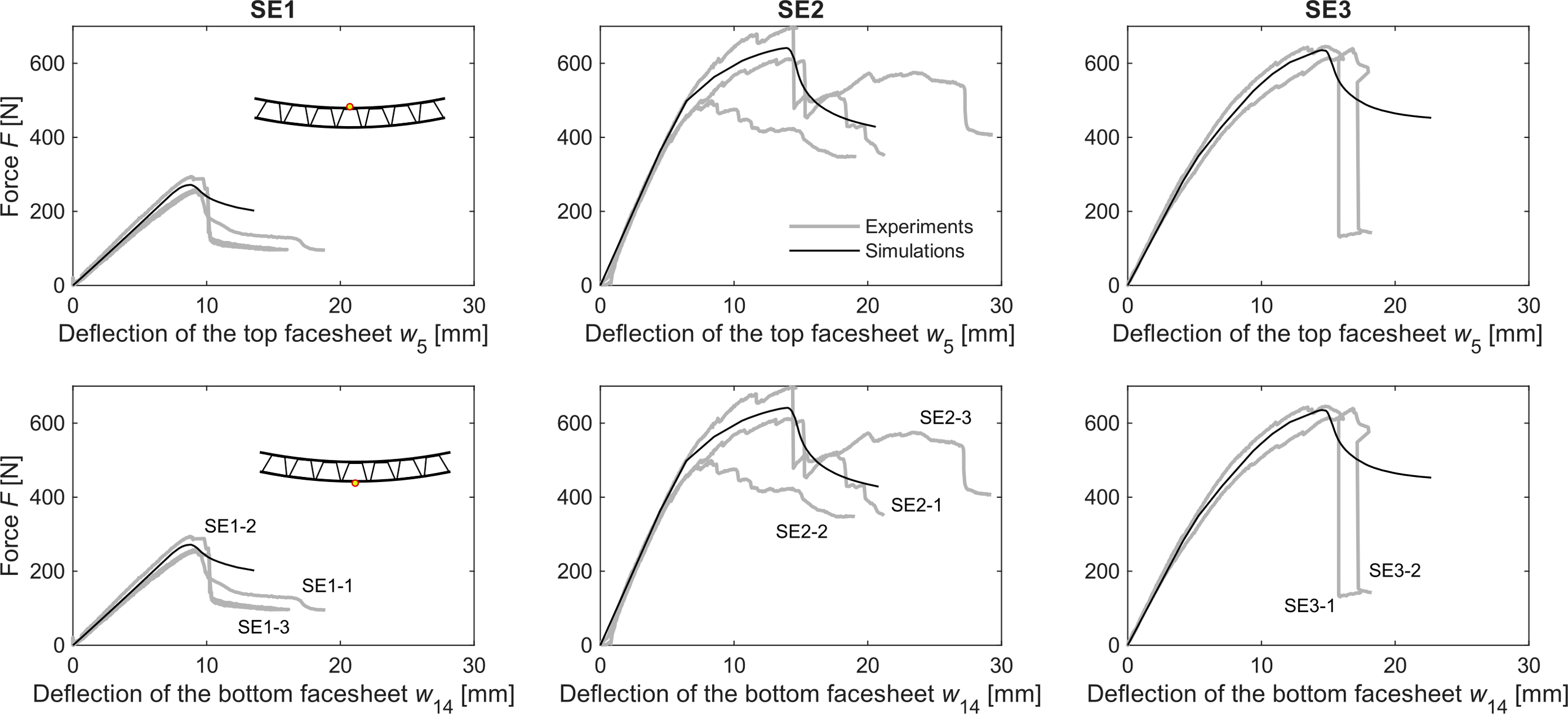
The sample SE2-2 exhibited low strength caused by delamination of a section of the facesheet material, as shown in Figure 8(a). Similarly, SE3-1 experienced delamination failure, but it occurred after the compressive failure of the top facesheet, which did not significantly affect its strength. In the non-linear displacement range of samples SE2-1, SE2-3, SE3-1 and SE3-2, small kinks in force graphs can be observed. These kinks are caused by stress redistribution in turn emanating from effects of localized high stress levels near the edges of the cups and minor slippage at the supports. The stress concentrations in the core are plotted as von Mises stress in Figure 8(e) for a beam of the type SE2 at peak force. Although the post peak behavior varies among the samples, a sudden drop in force after reaching the peak force is common in all cases, primarily due to the compression failure in the top facesheet. Results from FE simulations (solid black lines) showed good agreement with the experimental force-deflection graphs in several aspects: (i) they accurately captured the initial linear elastic behavior, which was expected as this region was used for calibrating the model, (ii) they effectively simulated the development of the plastic regions, and (iii) they successfully predicted the beams peak load. It is important to note that the small kinks observed in the experimental curves are not reflected in the FE-simulations. This is because phenomena like minor cracks in the glue line, small delamination within the material and support slip were not accounted for in the FE model. However, the stress concentrations observed in the FE-model within the core do indicate critical zones that could lead to local damages.
In Figure 7, the displacements from all DIC markers w along with the FE predictions are illustrated at a specific load level within the linear elastic region and the peak force of the load-displacement curves for each beam configuration. Two main observations are (i) the slightly changing curvature in the vicinity of the support plates at the displacements in the linear region and (ii) the local failure of the compressed facesheet at peak force. The first is caused by the shear stiffness provided by the core units while the latter indicates that better properties in the top facesheet could increase the load bearing capacity. Vertical displacements of the facesheets along the beams at the linear regime and the peak force. The light grey dots are from DIC target measurements and the black solid curves are from the simulations.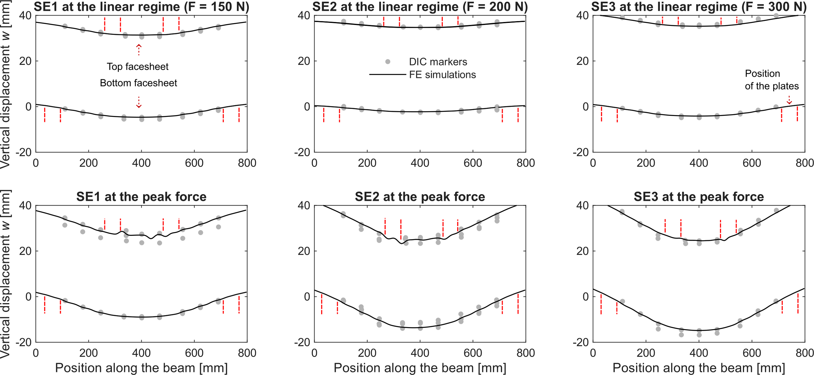
In Figure 8(c) the equivalent plastic strain in the top facesheets is presented at the peak force and post-peak force, set to 80% of the peak force, for the beam configurations. SE1 shows a higher and localized PEEQ already at the peak force compared to the others having more uniformly distributed PEEQ. It explains the premature failure of SE1 seen in the experiments. At post-peak force, the buckling failure develops diagonally and close to the top steel plates as seen in the experiments; The main failures in the top facesheets are illustrated in Figure 8(b). (a) Photo of the damage of each sample in the experiments, (b) typical damages that occurred in the top facesheets, (c) equivalent plastic strain at peak force and post-peak force (80% of the peak force) from the FE simulations, (d) stress in x-direction (σ
x
) in SE2 at peak force and (e) von Mises stress in the core at peak force showing stress localization.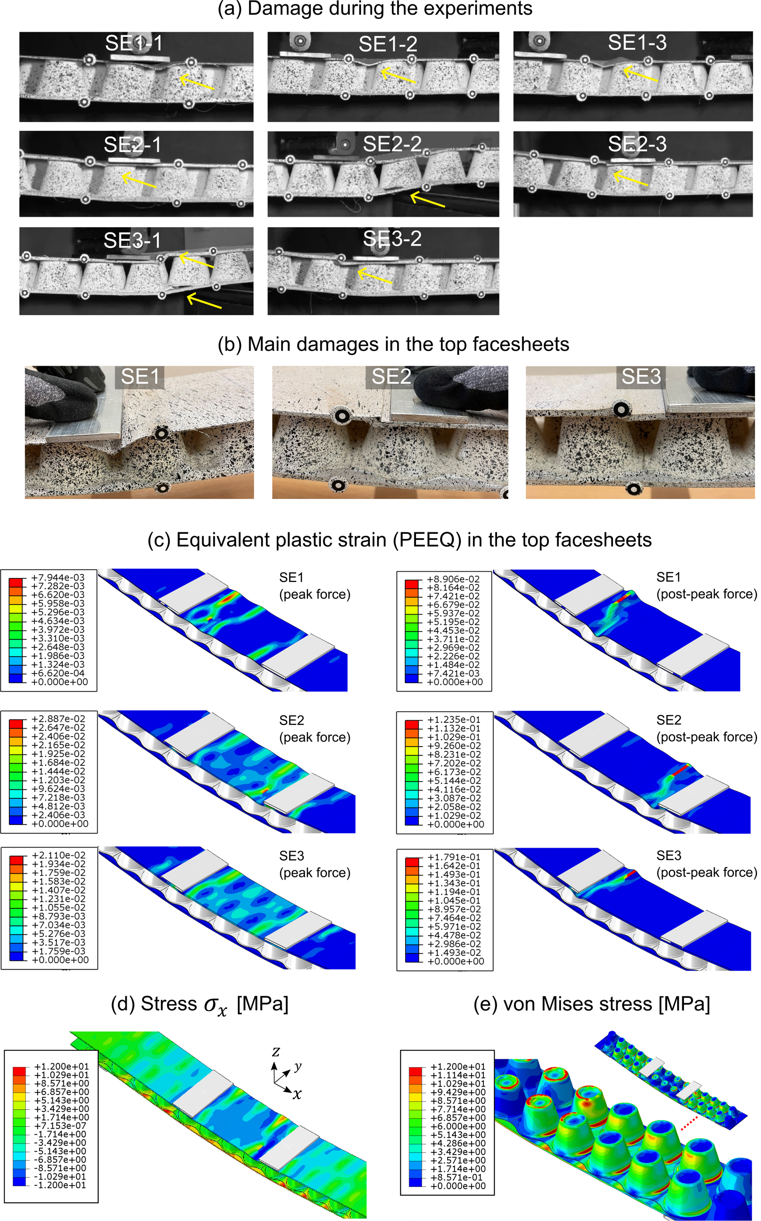
Compressive stress-strain curves of the facesheets from simulations
For the plasticity region in the model, the main inputs are values of yield stresses and plastic strains of the top facesheets. The tabulated set of values in Abaqus that provided good fit to the experimentally obtained results presented in Figures 6 and 7 are plotted as markers in Figure 9. The values were calibrated until the buckling appearance and therefore the compressive yield strengths at buckling onset are the last data points in graph. As an example, Figure 8(d) shows the compressive stress in the top facesheet in SE2 at peak force. The values ( Stress-strain curves of the compression behaviour of the facesheets. The solid grey curves are fitted to the experimentally obtained values indicated by markers.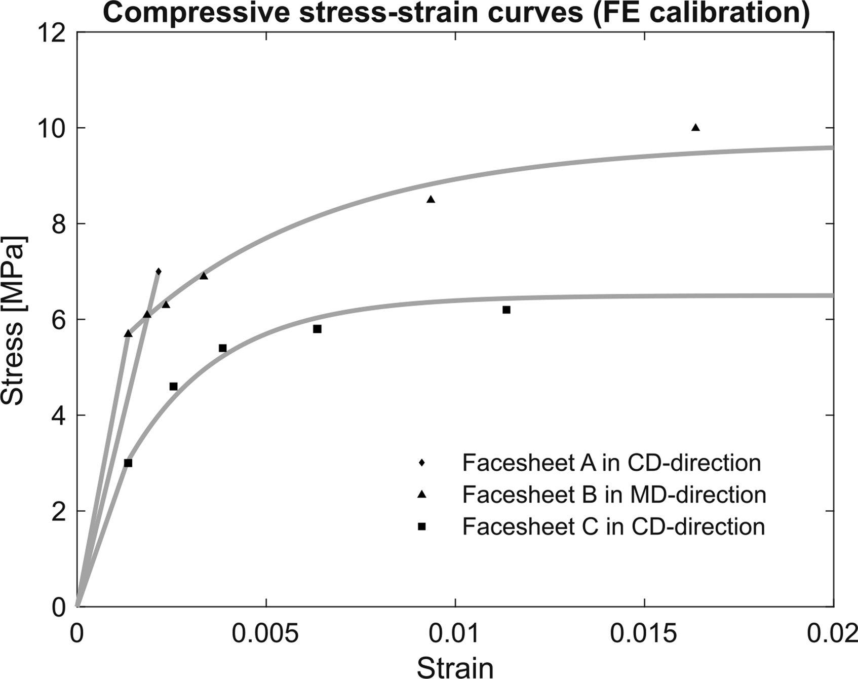
The facesheet A has only one value for initial yield stress σY0 because it experienced buckling at loads lower than those causing plasticity to develop in the top facesheet. On the contrary, facesheets B and C have some data in the plastic region. The shapes of the hardening functions fitted in Figure 6 by using equation (7) are
By comparing the materials, the initial yield stress in the CD-direction of the facesheet A drops by a factor of 3.5 to the hybrid paper material facesheet C. In the same direction, the figures can be compared with the literature, but in tension behaviour. Li et al.
10
found that the stress-strain curves in tension and compression of laminated paperboards do not differ much between the MD and the CD-direction, which permits making comparisons of our compression strain-strain curves to tensile stress-strain curves as tensile tests have more data in the literature. For example, Malin et al.13,14 have studied tested similar paperboards. Analyzing the facesheet A as it has a conventional composition with only virgin wood fibers, the initial yield stress has similar values as Scandinavian duplex FBB multiply boards, which indicates that the alternative way of using the FE model of the sandwich beam to estimate the material properties are reliable. The CD-modulus of facesheet A
Structural optimization of the core material
In this section, the model is exploited to optimize the geometry of the core in the beams subjected for the four-point bending test. This is done by maximizing the initial global stiffness with respect to the weight of the beam,
From the paper processes, the shape of the core cups is more adjustable since it is manufactured by moulding, whereas the facesheets can only be adjusted by varying their thickness. For this study, we therefore considered the optimization for the core units only and assume the three facesheets A, B and C as references with their respective configurations SE1, SE2 and SE3. The parameters to be optimized are the thickness
Figure 10 shows the normalized global stiffness per unit weight as a function of the parameters. The optimal values are obtained when the normalized global stiffness is 1. The figure is organized so that the thickness of the core Global stiffness per unit weight for SE1, SE2 and SE3 beams: Graphs with optimum height of the core against core thickness on the left, and graphs with optimum thickness against the height of the core on the right.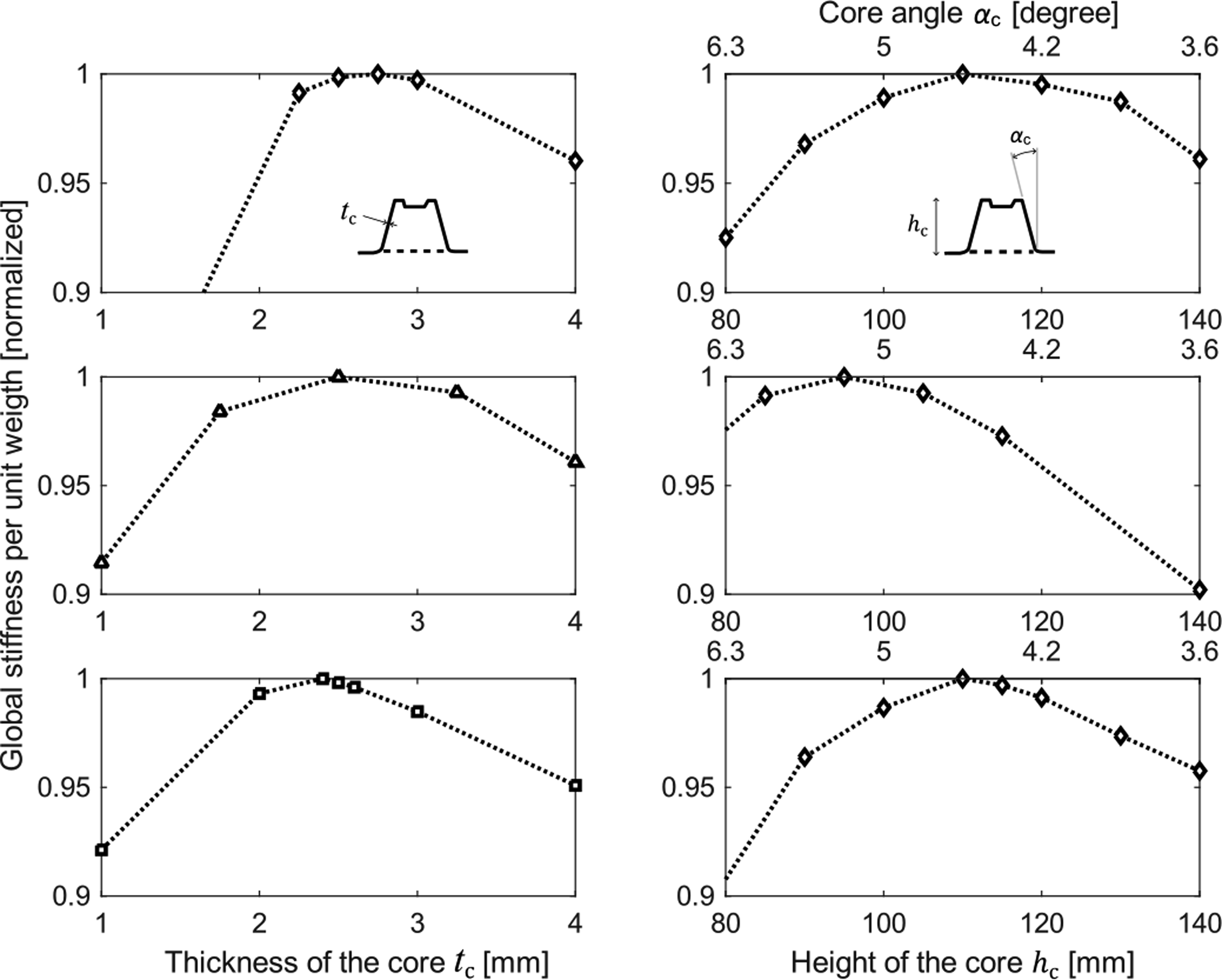
Conclusion
Innovative load-bearing sandwich beams with cup-box core produced in different configurations from paper materials were analysed in quasi-static bending. The top facesheets yielded first due to the lower strength in compression than in tension in paper materials. For this design, therefore, one of the critical design issues is the compressive strength of the top facesheets. The main initial failure was observed in the top facesheets, but there was a case of delamination of the core from the facesheet, which caused lower strength. Beams made of facesheets of thickness tf ≈1 mm were more susceptible to premature buckling failure, whereas those made of thicker facesheets (tf ≥ 2 mm) withstood buckling failure and behaved ductile due to yielding before failure. It was thus reaching higher beam deflections before failure.
The work has shown an alternative way to estimate elastic moduli of the facesheets along the beams via local bending stiffness using the displacements of DIC markers in the constant-moment regions. The flexural rigidity therefrom was estimated. Shear rigidities, which is strongly related to the in-plane elastic modulus of the core material, were estimated from the mid deflection and showed large scatter for all beam configurations. This scatter was mainly related to difficulties during the tests as the bending rigs allow rotations in all axis. That in turn occasionally caused twisting of the sandwich beams due to the asymmetry of the core, the non-centered positions of the beams in the rigs and local non-intentional deformation at supports. The analysis of shear rigidities indicates that cup-box core outperformed some commercial foam cores. An attempt was made to compare the cup-box core to paper honeycomb cores, but the literature values vary due to differences in core shapes, core densities, material orientations and paper materials used and potentially climate conditions. This work suggests conducting similar analyses in the same experimental conditions for more accurate comparisons of sandwich element counterparts.
The developed FE model calibrated with the local bending stiffness and shear rigidities obtained good agreement with experiments in force-deflection diagrams including the prediction of peak load before the top-facesheet failure. It also predicted the development of plasticity and the diagonal buckling behavior in the compressed facesheets. For this analysis, the equivalent plastic strains are relevant to compare the FE results with the experimental observations. Once calibrated, the model is used to estimate the modulus of elasticity for the facesheet materials and the in-plane modulus of the core material. Furthermore, it is used to estimate the compressive initial yield stress and shapes of the hardening functions of the facesheets. In this aspect, this work suggests further investigations in conventional mechanical material tests for the studied paper materials to be compared to the material data obtained from the structural level tests performed herein.
Optimizing the global stiffness is an efficient way to design the cup-box core geometry using the developed FE model. For bending according to the presented load case, this study suggests that the optimal thickness and height of the core for all cases are in average tc = 2.5 mm and hc = 105 mm, which is approximately 3 times higher than the original values used.
Supplemental Material
Supplemental Material - Analyses of bending performance of innovative paper-based sandwich beams with cup-box core
Supplemental Material for Analyses of bending performance of innovative paper-based sandwich beams with cup-box core by Marcus V Tavares da Costa, Mikael Perstorper and Johan Vessby in Journal of Sandwich Structures and Materials
Footnotes
Acknowledgements
Ecopals AB, Smurfit Kappa Sverige AB and Rottneros Packaging AB are acknowledged for supplying the materials and sharing their knowledge in pulp and paper processes. The authors are grateful for the research funding from the Knowledge Foundation (KKS), KK project number 20210063. Mr Maxim Nilsson and Mr Emil Lockner are also acknowledged for their assistance in the experimental tests.
Declaration of conflicting interests
The author(s) declared no potential conflicts of interest with respect to the research, authorship, and/or publication of this article.
Funding
The author(s) disclosed receipt of the following financial support for the research, authorship, and/or publication of this article: This work was supported by the Stiftelsen för Kunskaps-och Kompetensutveckling (20210063).
Supplemental Material
Supplemental material for this article is available online.
References
Supplementary Material
Please find the following supplemental material available below.
For Open Access articles published under a Creative Commons License, all supplemental material carries the same license as the article it is associated with.
For non-Open Access articles published, all supplemental material carries a non-exclusive license, and permission requests for re-use of supplemental material or any part of supplemental material shall be sent directly to the copyright owner as specified in the copyright notice associated with the article.