
Abstract
Sandwich beams, comprising two stiff facesheets bonded to a core, are light and strong and see widespread application. However, debonded regions between the facesheets and the core can significantly reduce the strength and have an impact on the vibration behaviour. In this study, the previous literature was referred to, and finite element simulations were conducted using ANSYS on debonded sandwich beams with [0°]4, [+45°/−45°]S and [90°]4 carbon fibre reinforced polymer facesheets. The effects of the configurations of the three debonded regions and facesheet stacking orientations were studied. The most important finding is that if debonds cover vibration nodes, the natural frequencies drop more significantly because the stiffness decreases more. It was determined that when there were debonded regions, the natural frequencies of the bending modes of the beams using [0°]4 facesheets decreased more compared to those of the beams using [+45°/−45°]S and [90°]4 facesheets; while the trends are opposite for the natural frequencies of torsion modes of the beams using [+45°/−45°]S facesheets. Reducing the natural frequency can cause a structure to vibrate at the resonance frequency, leading to structural failure. This study contributes to furthering our understanding of how different debonds and facesheet stacking orientations affect the vibrations of sandwich beams.
Introduction
Composite sandwich structures, comprising a light core and two strong and stiff facesheets, are being widely used for various applications, such as wind turbine blades, aircraft wings and ship decks. While the core of sandwich structures is usually thick and light, the facesheets are thin and strong, rendering these structures with a low density and high flexural stiffness and, thus, the ability to withstand heavy loads. Fibre reinforced polymers (FRPs), such as carbon fibre reinforced polymers (CFRPs), are often used as facesheets. Because sandwich structures comprise at least two different materials, the mechanical behaviours of composite structures are more complicated and, thus, widely studied.1–3 It was found that the stacking orientations of FRP laminates can significantly affect the mechanical behaviours, e.g. flexural stiffness, of sandwich structures.4,5
To prevent the failure of sandwich structures, it is essential to perfectly bond the facesheets and the core. Face-core interfacial debonding is a critical issue that causes the failure of sandwich structures6,7; this is because debonding at the adhered regions between the facesheets and the core may occur due to manufacturing flaws or in-service damage.8–11 Debonded regions can lead to crack growth, strength and stiffness reduction, and failure. The flexural rigidity, stiffness and strength reductions are more significant for a longer debonded region.12,13
Vibration is a key factor in structural applications because large displacements, damage and structural failure can be induced by resonance. Since sandwich structures comprise at least two different materials, their vibration behaviours are more complicated. Various approaches have been explored to analyse the vibration behaviours of these structures and predict the mode shapes and natural frequencies.14–22 A spline finite strip method was developed to analyse the natural frequencies of rectangular sandwich plates; the results were in sound agreement with those of other studies. 15 It was found that the fundamental frequencies increase with an increase in the skew angles of the parallelogram sandwich plates.18,21 The modified displacement field expressions used to analyse the free vibrations of cylindrical sandwich structures contributed to rapidly converging and accurate results. 22
Among the various methods developed for analysing the vibrations of sandwich structures, finite element analysis is one of the most studied approaches. A higher-order layerwise finite element model was developed and used to predict the free vibration behaviours of multilayer sandwich plates. The designed model is simpler than previous ones and can predict accurate results. 17 Additionally, an improved higher-order one-dimensional beam element was proposed to derive reasonably accurate results as three-dimensional elements while significantly reducing the computation cost. 23 Through finite element analysis, it was found that facesheet stacking orientations have a significant impact on the stiffness of the structures, thereby impacting the natural frequencies and mode shapes.17,18,24–26 It was also found that the geometry and curvature of the structures can significantly influence vibration behaviours.25–27 Moreover, increasing the layers of the cores or using multiple cores can also affect the natural frequencies of sandwich structures significantly.28,29
Since debonded regions in sandwich structures can reduce system stiffness, the vibration behaviours of sandwich structures are also affected by debonded regions. The effects of size and location of debonded regions on the vibrations of sandwich structures have been widely studied and are deemed essential factors.27,30,31 Since a longer debonded region results in greater stiffness reduction, the structure’s natural frequencies decrease more significantly.13,32–34 If two debonded regions are located symmetrically with respect to the middle plane of the structure, the natural frequencies can reduce further. 32 The curvature of structures can also influence vibration behaviours.25,27,31,35 Compared to flat structures, it was revealed that the mode shapes and natural frequencies of the lateral and torsion modes of curved sandwich structures are affected more significantly by debonded regions.25–27,31
For practical applications, operating structures or devices near low natural frequencies should be avoided because resonance is more likely to be excited at these frequencies, which can cause large displacements and lead to failure. To prevent structural resonance, measuring the vibration behaviours of debonded structures can help identify damaged areas and locations, as a reduction in stiffness affects natural frequencies and mode shapes. Therefore, the measurement of vibration behaviours can be used as a non-destructive testing technique.36–38
The locations and sizes of debonded regions can significantly influence the vibration behaviours of sandwich structures. Also, according to the literature, stiffness and natural frequencies drop more significantly when the debonded region is longer than about one-fifth of the beam’s length. 13 However, the effects of multi-debonding have been less discussed. It was revealed that the shortest length of a single debond is equal to one-fifth (40 mm) of the beam’s length (200 mm) and that the longest length is up to two-fifths (80 mm) of the beam’s length.24,26 Furthermore, a single 80-mm debond was divided into two 40-mm debonds, and the effects of the locations of the two debonds on the vibration behaviours of sandwich structures were investigated.24,26 To further explore the effects of debonds, this study examined the effects of three 40-mm debonds on the mode shapes, natural frequencies and vibration nodes of sandwich structures with symmetric angle-ply facesheets. The aim was to identify how these factors affect the vibrations of composite sandwich beams.
Materials and material properties
The sandwich beams comprised an epoxy core and two CFRP facesheets. The epoxy resin, Araldite LY 556 from Huntsman, UK, was crosslinked and cured using Albidur HE 600, a curing agent supplied by Evonik, Germany. The CFRP facesheets were manufactured using the unidirectional carbon fibre fabric Gurit UT-C300, supplied by Marineware, UK. The glass transition temperature of the resin system was about 150°C.39,40
Materials and mechanical properties. 6
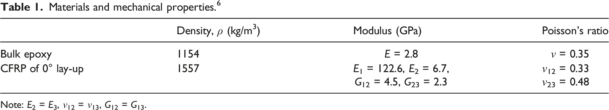
Note: E2 = E3, ν12 = ν13, G12 = G13.
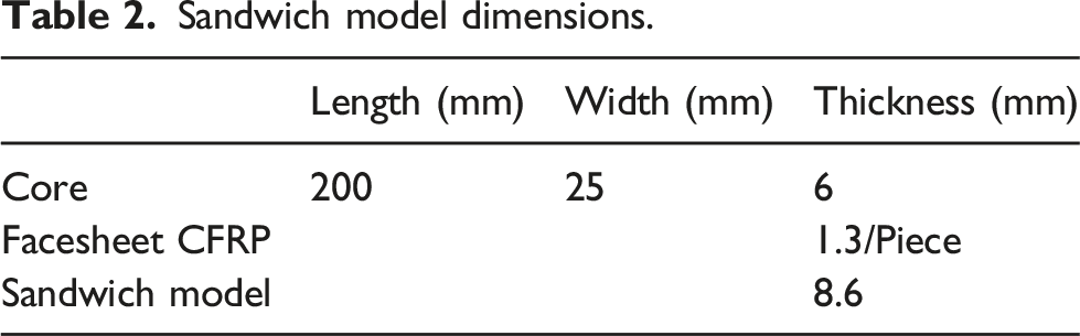
Sandwich model dimensions.
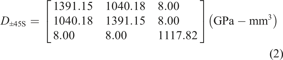
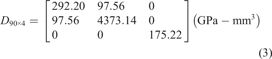
In this study, the stacking orientations of the facesheet CFRP were [0°]4, [+45°/−45°]S (symmetric angle-ply) and [90°]4. The bending stiffness matrix, D, of the sandwich beams, using the three types of facesheets, has also been calculated and reported.24–26 The values are listed below: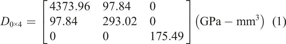
Finite element simulation
The commercial finite element simulation software ANSYS was used to simulate the natural frequencies and mode shapes of the debonded sandwich beams. The engineering data were set up based on the measured mechanical properties listed in Table 1. The dimensions of the developed three-dimensional models are listed in Table 2. While the debonded regions between the facesheets and the core were modelled using the “frictionless contact” function to prevent the facesheets from penetrating the core, the bonded regions were modelled using the “bonded contact” function. To investigate the effects of friction between the facesheets and the core on the vibration behaviours, “friction contact” (with different coefficients of friction [μ]) was also introduced into the debonded regions.
Each facesheet of the sandwich model comprised a 4-plies CFRP laminate. The stacking orientations were [0°]4, [+45°/−45°]S and [90°]4 by assigning different orientation angles to every ply. Free-free boundary conditions were set, and the modal analysis module, with the Block Lanczos method, was used to simulate the vibration behaviours of the intact and debonded sandwich beams. A convergence study was also performed on the perfectly bonded model. A linear 8-node SOLID185 cuboid element was assigned for meshing. The elements of the core had dimensions of 1 mm × 1 mm × 1 mm (length × width × thickness), while the elements of the facesheets had dimensions of 1 mm × 1 mm × 0.325 mm. The mesh resulted in 70,000 elements (20,000 for each facesheet and 30,000 for the core) and was adopted for subsequent simulations.
In this study, the sandwich beams with three 40-mm debonds with different separations (Δ) were studied. The debonded regions were located between the facesheets and the core, i.e., the adhered interfaces in real beams. The centre of separation was aligned with the centre of the beam and has a length of either 20, 40 or 60 mm. Models of the sandwich beams and the locations of the debonded regions are shown in Figure 1. Models of sandwich beams and debonding locations (shown in green). (a) Intact (no debond), and (b) three 40-mm debonds.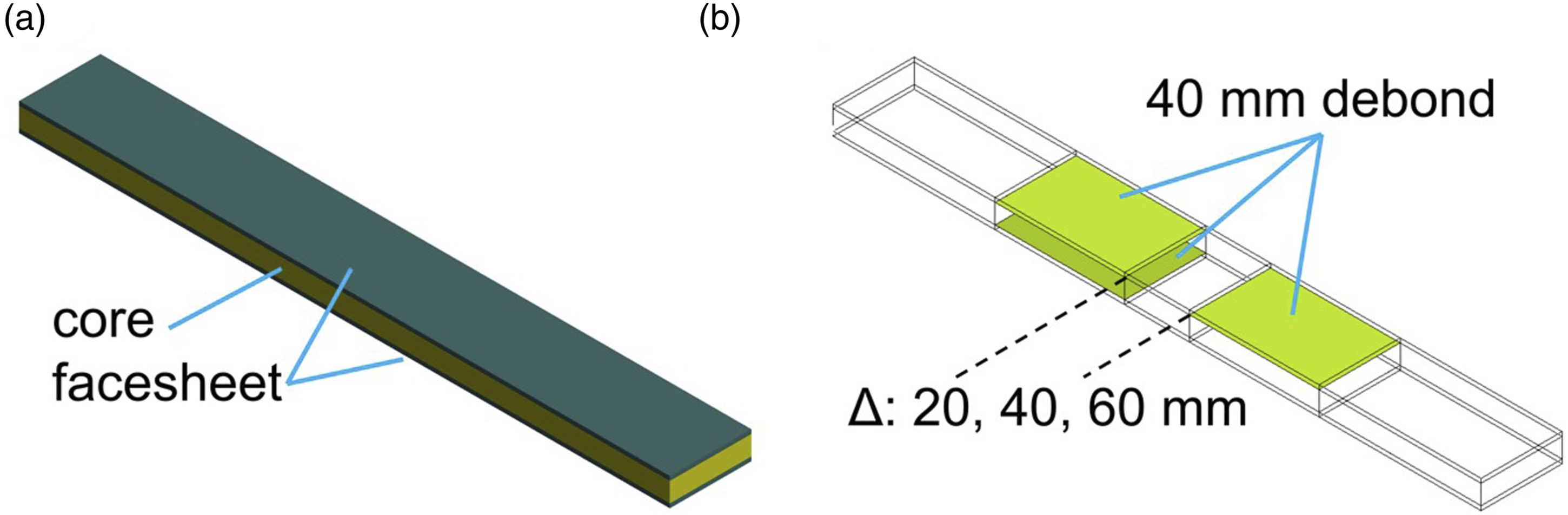
Simulated natural frequencies compared to reported values.
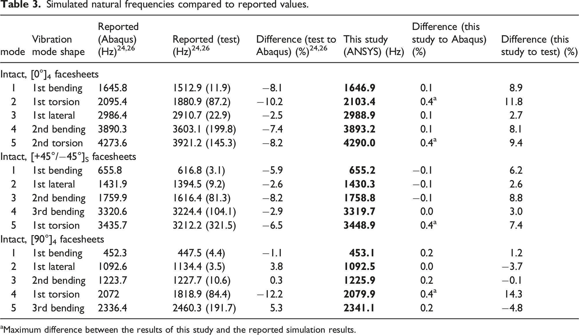
aMaximum difference between the results of this study and the reported simulation results.
Since both the simulated results showed good consistency, the simulation method used in this study was validated. The simulation methodology was then used for simulating the beams with the debonded regions.
Results and discussion
This study investigated the effects of CFRP facesheet stacking orientations ([0°]4, [+45°/−45°]S and [90°]4) and the configurations of three face-core interfacial debonded regions on the vibration behaviours of sandwich beams using finite element simulations. The mode shapes, natural frequencies and locations of vibration nodes are discussed in this section. To clarify the effects on the natural frequencies, the ratios of the debonded beams’ natural frequencies to the intact beams’ natural frequencies were used and presented in this study (i.e., relative frequency, fn/fn,intact, where n indicates the n-th vibration mode).
Intact sandwich beams
The effects of CFRP facesheet stacking orientations on the natural frequencies of the intact beams using [0°]4, [+45°/−45°]S and [90°]4 CFRP facesheets are briefly discussed in this section.
Figure 2 shows the first five mode shapes of the intact sandwich beam using [+45°/−45°]S facesheets. The first five modes and natural frequencies of the intact sandwich beams using the three types of CFRP facesheets are listed in Table 3. Notably, different facesheet stacking orientations resulted in different sequences and natural frequencies for the same mode. The natural frequencies of the first and second bending modes of the beam using [0°]4 facesheets (1646.9 Hz and 3893.2 Hz) were higher than those of the beam using [+45°/−45°]S facesheets (655.2.0 Hz and 1758.8 Hz) and [90°]4 facesheets (453.1 Hz and 1225.9 Hz). Additionally, the natural frequency of the first torsion mode of the beam using [+45°/−45°]S facesheets (2696.7 Hz) was higher than that of the beam using [0°]4 facesheets (2103.4 Hz) and [90°]4 facesheets (2079.9 Hz). Mode shapes of the intact sandwich beam using [+45°/−45°]S facesheets. (a) Mode 1: first bending. (b) Mode 2: first lateral. (c) Mode 3: second bending. (d) Mode 4: third bending and (e) Mode 5: first torsion.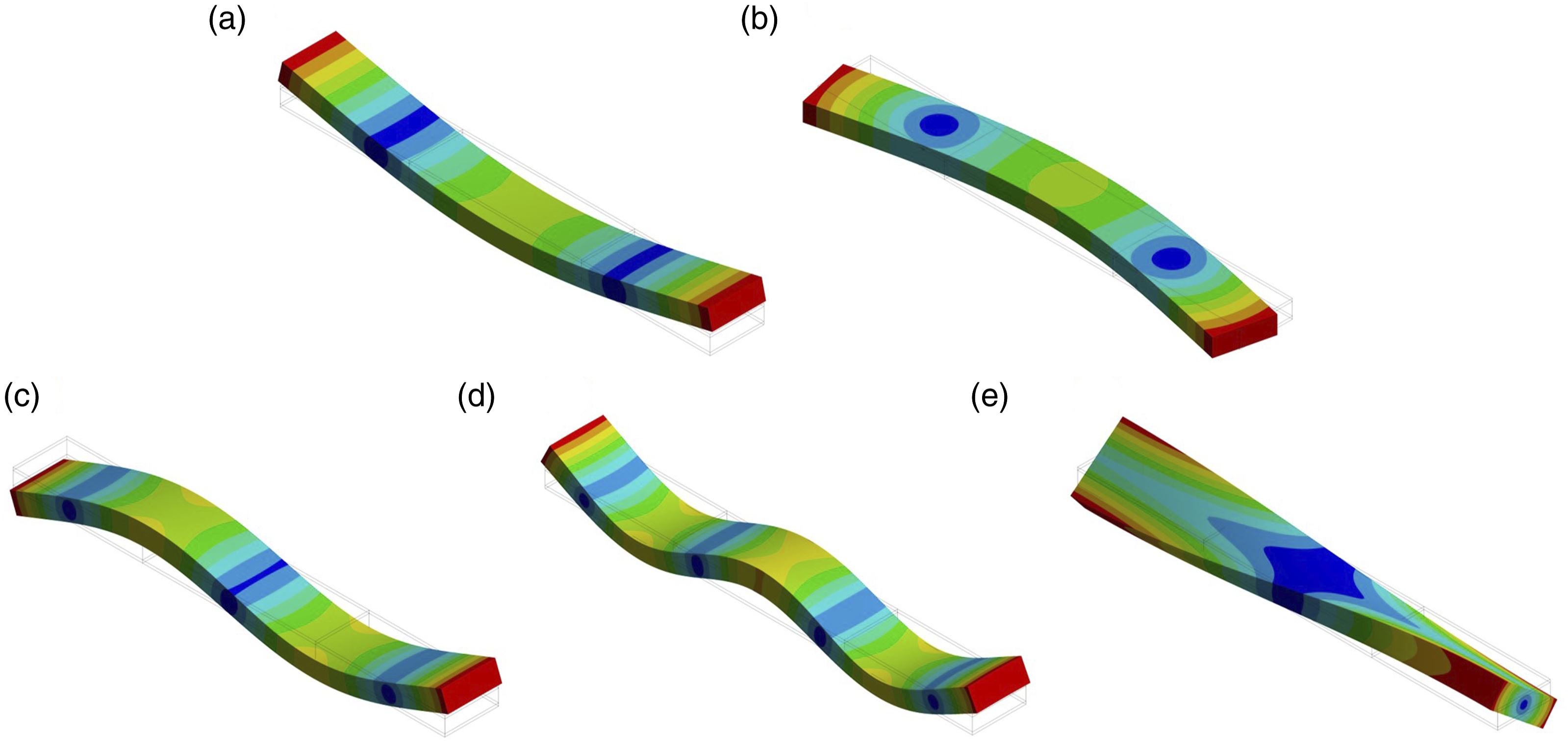
These differences stemmed from the anisotropic mechanical properties of CFRP facesheets. As shown in the bending stiffness matrices (see equations (1)–(3)), the d11 term in equation (1) is greater than that in equations (2) and (3) (4373.96 GPa-mm3 vs 1391.15 GPa-mm3 and 292.20 GPa-mm3), meaning that the beam using [0°]4 facesheets had a higher bending stiffness along the longitudinal direction and, thus, contributed to the higher natural frequencies of the bending modes. Meanwhile, the d66 term in equation (2) is greater than that in equations (1) and (3) (1117.82 GPa-mm3 vs 175.49 GPa-mm3 and 175.22 GPa-mm3), meaning that the beam using [+45°/−45°]S facesheets had a higher twisting stiffness and, thus, resulted in higher natural frequencies of the torsion modes.
Comparison with single and double debonds
Figure 3(a) compares the relative natural frequencies of the beams with three debonds (this study) to those of the beams with single or double debonds (previous studies).24,26 The stacking orientation of the facesheets of the compared beams was [0°]4. The models of the beams with single or double debonds are shown in Figure 3(b)–(e). The beams with two 40-mm debonds had the debonds at the same side, diagonal locations (D) and symmetric locations (S). The separation (Δ) between the two debonds was 20 mm. (a) Relative natural frequencies of the intact sandwich beam and the beams with one, two and three debonds and the models of sandwich beams with debonds: (b) single 40-mm, (c) two 40-mm on the same side, (d) two 40-mm at diagonal locations (d) and (e) two 40-mm at symmetrical locations (S). (b)–(e) are reproduced from previous studies.24,26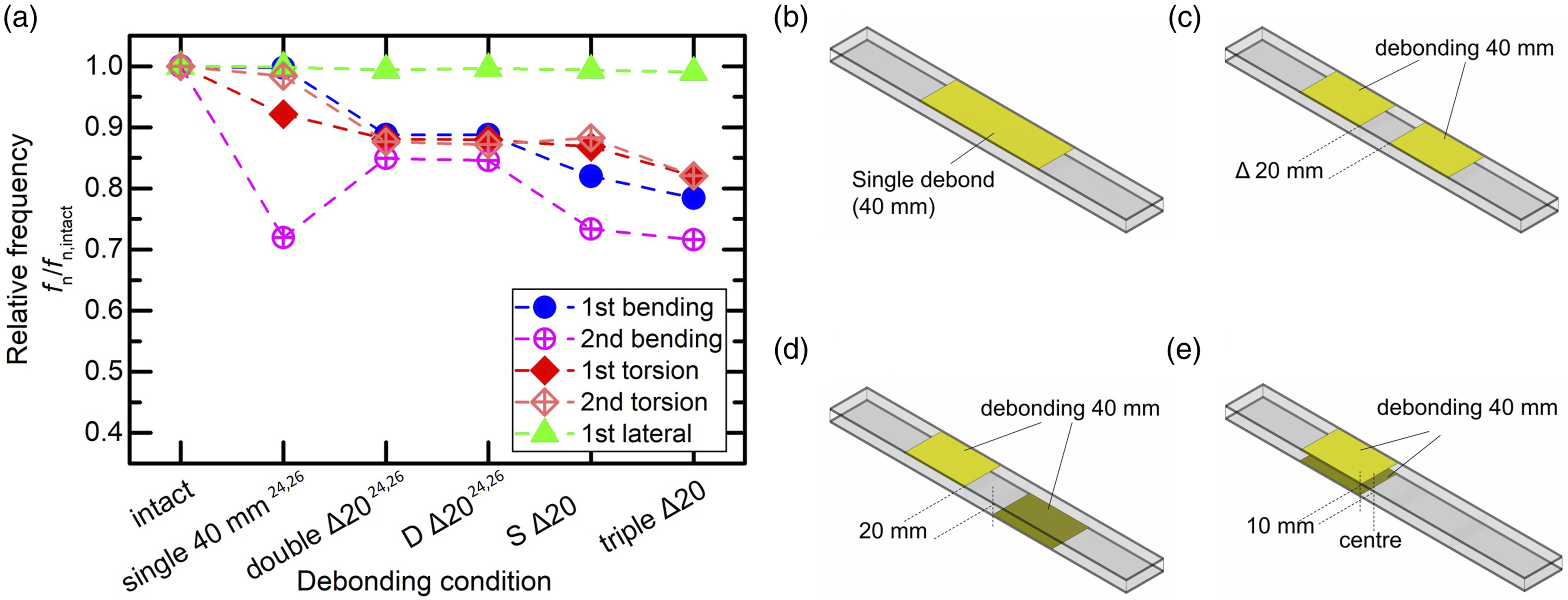
According to previous studies, reductions in natural frequencies have not shown the same trend. For example, the natural frequency of the first bending mode decreased when it changed from “single 40 mm” to “double Δ20”, while the natural frequency of the second bending mode increased for the same change in debond configuration. As revealed by previous studies, in addition to the number of debonds, the vibration nodes being overlapped by debonds can also affect the stiffness of the beam and, thus, the natural frequencies.24–26
When the number of debonds increased from two to three, except for the first lateral mode, all the modes showed reductions in the natural frequencies (see Figure 3(a)). This is because the total length of the debonded regions increased, which led to more reduction in the stiffness, thereby causing the natural frequencies to decrease more significantly. The first lateral mode showed no significant change in the natural frequencies since the lateral vibration was not sensitive to the horizontal debonds.24–26
Effects of friction at the debonded regions
To simulate a more realistic condition that there can be friction between the facesheets and the core, different coefficients of friction (μ) were introduced into the debonded regions. The effects of friction on the relative natural frequencies of the beams with three debonds are shown in Figure 4. The facesheet stacking orientation of the beams was [0°]4. Notably, when there was no friction, the natural frequencies decreased the most for the bending and torsion modes; however, when μ was increased slightly to 0.01, the natural frequencies of the bending and torsion modes increased significantly. When μ was further increased to 0.05, the relative natural frequencies became almost equal to 1, i.e., the frequencies of the debonded beam became the same as the intact beam. On the other hand, friction had little effect on the relative natural frequencies of the lateral modes because the lateral modes were not sensitive to the debonds. Effects of coefficient of friction on the relative natural frequencies of the triple-debonded beams using [0°]4 facesheets.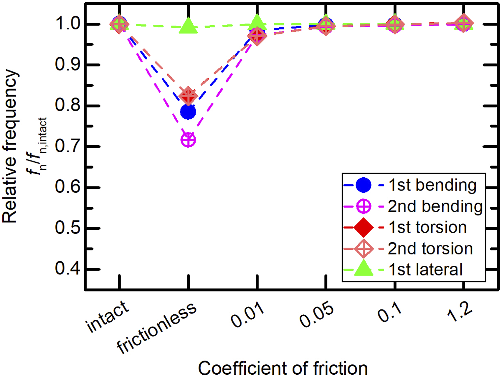
The reason for the increase in the natural frequencies with an increase in friction is that friction limited the relative movements between the facesheets and the core at the debonded regions. Since the beams could not have relative movements at the debonded regions, their stiffness increased. Therefore, the natural frequencies also increased.
Effects of increasing the separation between the three debonds
Figure 5 shows the frequency ratios of the sandwich beams with three debonds. The beam model is shown in Figure 1(b). The beams with three debonds were left-right asymmetric, resulting in the asymmetry of the mode shapes. According to Figure 5, when Δ was increased, the relative frequencies of the debonded beams using the three types of facesheets showed the same trend for the same mode. Relative natural frequencies of the sandwich beams with three debonds. (a) [0°]4, (b) [+45°/−45°]S and (c) [90°]4 facesheets.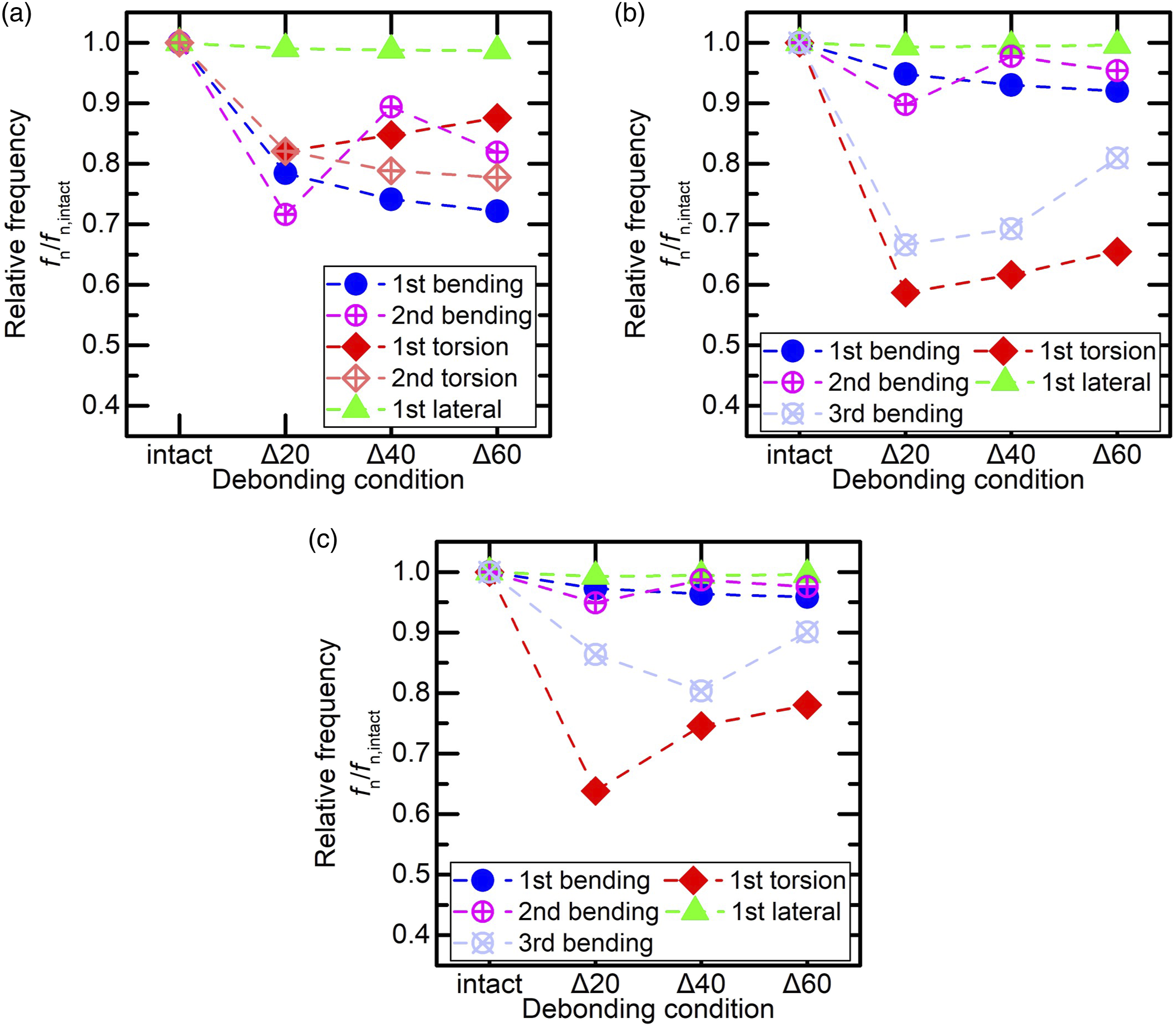
Notably, for the same bending mode and same Δ, the frequency ratios of the beam using [0°]4 facesheets reduced more compared to those of the beams using [+45°/−45°]S and [90°]4 facesheets. Moreover, for the torsion modes, the frequency ratios of the beam using [+45°/−45°]S facesheets decreased more compared to those of the beams using [0°]4 and [90°]4 facesheets. Although [0°]4 facesheets provided the highest bending stiffness (i.e., d11 in equation (1), 4373.96 GPa-mm3), when there were debonded regions, the reduction in the bending stiffness was more significant, resulting in greater reductions in the natural frequencies of the bending modes. For the same reason, [+45°/−45°]S facesheets provided the highest twisting stiffness (d66 in equation (2), 1117.82 GPa-mm3). When there were debonded regions, the reduction in the twisting stiffness was more significant, resulting in greater reductions in the natural frequencies of the torsion modes.
In this study, if a vibration node was not covered by any debond and was situated more than 5 mm away from the edges of the debond, it was defined as not covered (NC); if a node was not covered but was located at a distance of within 5 mm from the edges of the debond, it was defined as near debond (ND); if a node was covered by a debond and was located within 5 mm from the edges of the debond, it was defined as just covered (JC); and if a node was covered by a debond and was located 5 mm away from the edges of the debond, it was defined as fully covered (FC).
When Δ increased from 20 to 60, the frequencies of the first bending mode of the beams using all types of the facesheets showed decreasing trends (see Figure 5). This can be attributed to the overlaps between the nodes and the debonds. For example, for the beam using [0°]4 facesheets, when Δ increased from 20 mm to 40 mm, the right node changed from JC (Figure 6(a)) to FC (Figure 6(b)) by the right debond, while the left node remained FC by the left debonds. For the beam using [+45°/−45°]S facesheets, when Δ increased from 20 mm to 60 mm, the two nodes changed from ND (Figure 6(c)) to FC (Figure 6(d)) by the debonds. Also, for the beam using [90°]4 facesheets, the two nodes also became FC by the debonds with an increase in Δ from 20 mm to 60 mm, see Figure 6(e) and (f). Mode shapes and nodes of the first bending mode of the sandwich beams with three debonds. (a) [0°]4, Δ20. (b) [0°]4, Δ40. (c) [+45°/−45°]S, Δ20. (d) [+45°/−45°]S, Δ60. (e) [90°]4, Δ20, and (f) [90°]4, Δ60.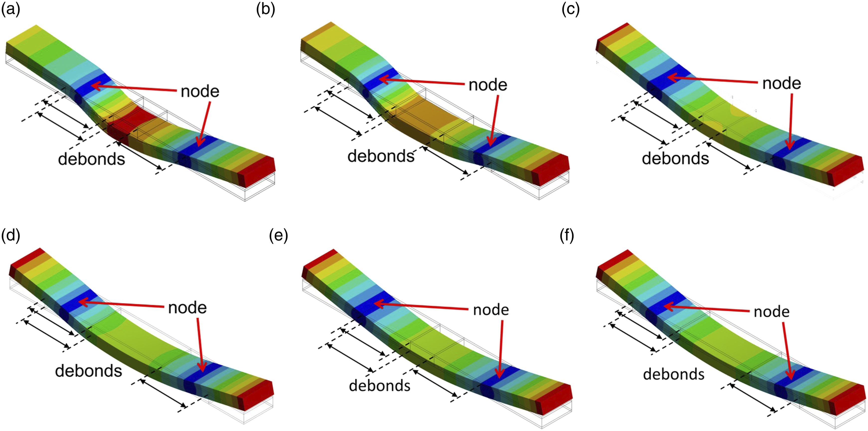
For vibration, the nodes were located where the structures had no displacements. However, when the debonds covered the vibration nodes, the facesheets and the core near these regions could exhibit relative movement, which led to a significant reduction in the bending stiffness and, thus, resulted in greater reductions in the natural frequencies.
For the second bending mode of the beams using all types of facesheets, the frequencies first increased (from Δ20 to Δ40) and then decreased (Δ40 to Δ60), see Figure 5. When Δ increased from 20 mm to 40 mm, the overlapping conditions of the left and right nodes remained uncovered by any debond. However, the overlapping condition of the centre node of the beam using [0°]4 facesheets changed from FC (Figure 7(a)) to JC (Figure 7(b)) by the two debonds on the left. The overlapping condition of the centre node of the beam using [+45°/−45°]S facesheets changed from JC (Figure 7(d)) to NC (Figure 7(e))by the two debonds on the left, and that of the centre node of the beam using [90°]4 facesheets remained uncovered by any debond (see Figure 7(g) and (h)). Therefore, the relative movements between the facesheets and core around the centre nodes became smaller or restricted. Therefore, the natural frequencies of the second bending mode of the beams increased. Mode shapes and nodes of the second bending mode of the sandwich beams with three debonds. (a) [0°]4, Δ20. (b) [0°]4, Δ40. (c) [0°]4, Δ60. (d) [+45°/−45°]S, Δ20. (e) [+45°/−45°]S, Δ40. (f) [+45°/−45°]S, Δ60. (g) [90°]4, Δ20. (h) [90°]4, Δ40, and (i) [90°]4, Δ60.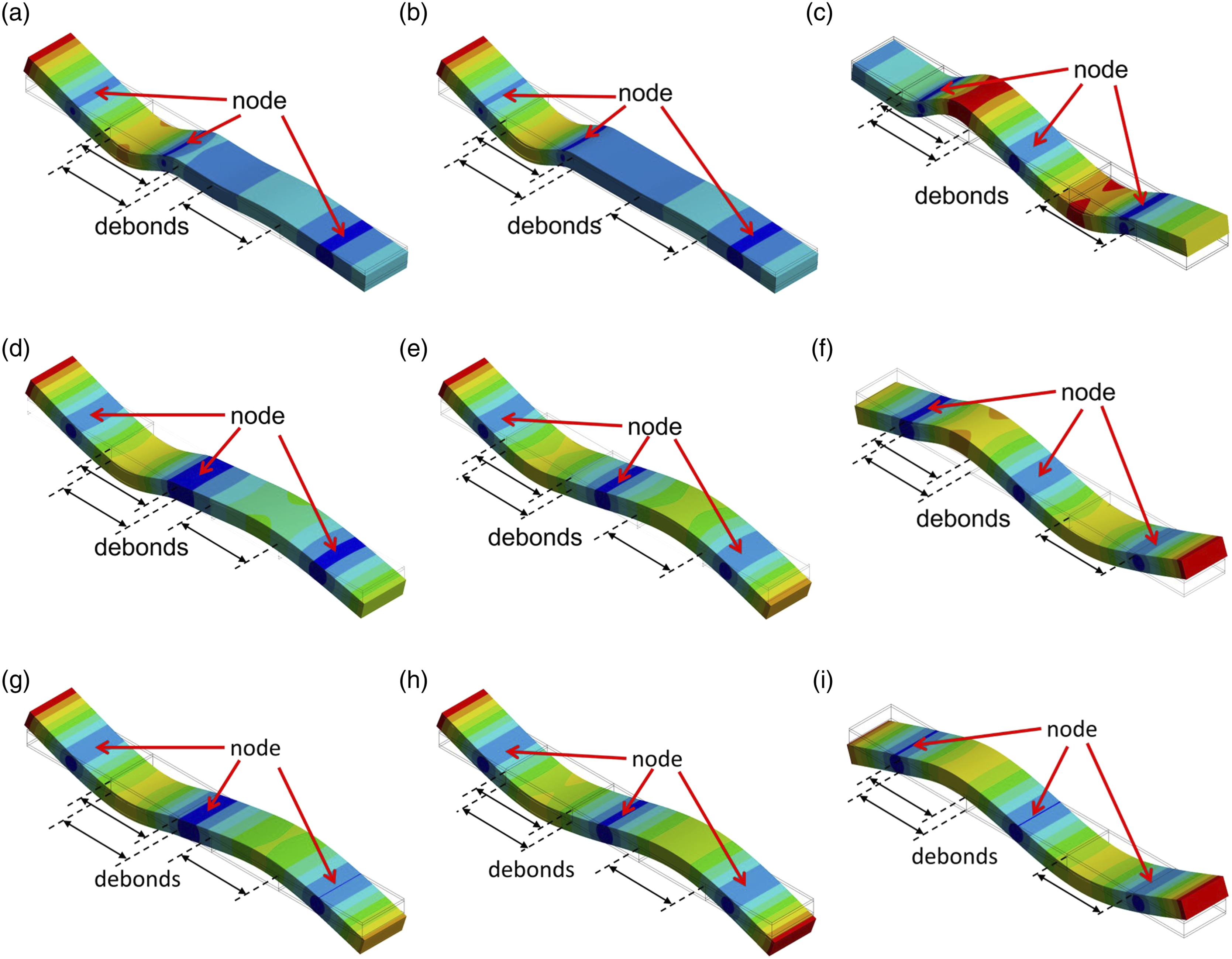
However, for the second bending mode, when Δ was increased further from 40 mm to 60 mm, the centre nodes of all the beam types did not get covered by any debond. However, the left and right nodes of the beam using [0°]4 facesheets were fully covered by the debonds (see Figure 7(c). Meanwhile, the left and right nodes of the beam using [+45°/−45°]S facesheets were covered by the two debonds on the left and the debond near the right, respectively (see Figure 7(f)), and the left and right nodes of the beam using [90°]4 facesheets approached closer to the debonds (see Figure 7(i). This allowed for larger relative movements between the facesheets and the core around the left and right nodes, resulting in reductions in the frequencies.
For the first torsion mode, increasing Δ from 20 mm to 60 mm increased the frequencies (see Figure 5(a) and (b)). For the beam using [0°]4 facesheets, the overlapping condition of the only node changed from JC by the two debonds on the left (Δ20, Figure 8(a)) to NC (Δ40 and Δ60, Figure 8(b) and (c)) by any debond. For the beam using [+45°/−45°]S facesheets, the overlapping condition of the node changed from FC by the two debonds on the left (Δ20, Figure 8(d)) to JC (Δ40 and Δ60, Figure 8(e) and (f)) by the two debonds. Additionally, for the beam using [90°]4 facesheets, the overlapping condition of the node changed from FC by the two debonds on the left (Δ20, Figure 8(g)) to near the two debonds; however, they were NC (Δ60, Figure 8(i)). Therefore, the relative movements between the facesheets and the core around the node became smaller or restricted, resulting in increases in the natural frequencies of the first torsion mode. Mode shapes and nodes of the first torsion mode of the sandwich beams with three debonds. (a) [0°]4, Δ20. (b) [0°]4, Δ40. (c) [0°]4, Δ60. (d) [+45°/−45°]S, Δ20. (e) [+45°/−45°]S, Δ40. (f) [+45°/−45°]S, Δ60. (g) [90°]4, Δ20. (h) [90°]4, Δ40, and (i) [90°]4, Δ60.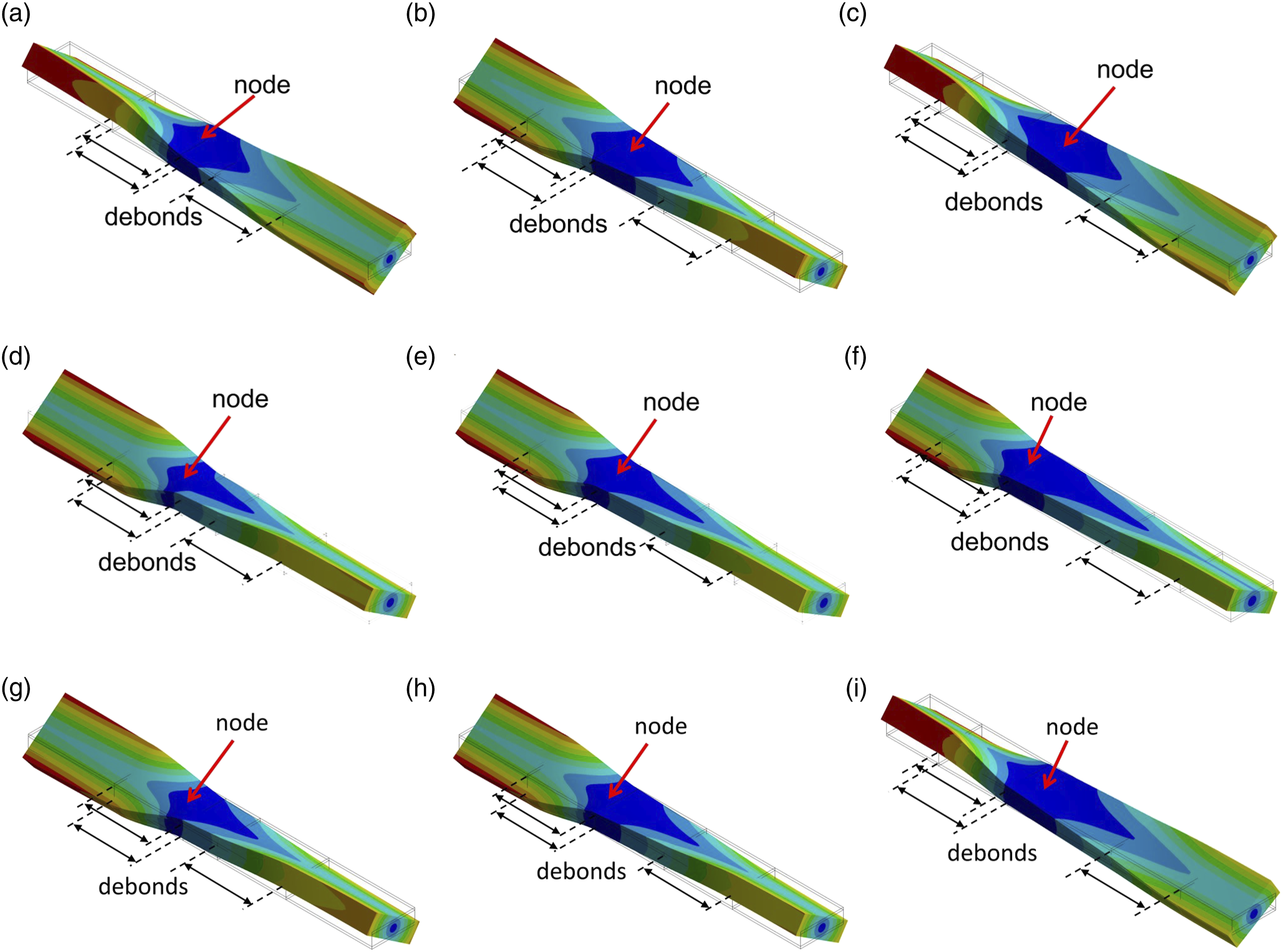
From the discussion thus far, it is clear that facesheet stacking orientation can impact the locations of vibration nodes. However, by investigating the coordinates of the vibration nodes for each mode and debonding configuration, it was found that compared to the shift amount of the debonds, the changes in locations of the nodes were not significant; this can be observed from Figures 6–8. The effects of facesheet stacking orientation will be further discussed in the next section.
Notably, for the debond configurations used in this study, no significant local vibration mode of the debonded regions was observed, based on the simulated mode shapes, as shown in Figures 6–8. The local modes appeared when the debonded regions became longer or were at a higher mode. Since the length of the debonded regions simulated in this study was 40 mm (one-fifth of the beam length) and since the modes discussed were the lowest five ones (which were at lower frequencies), the facesheets and the core at the debonded regions did not exhibit local vibration modes.
Effects of facesheet stacking orientation on the node position
Overlapping conditions of the nodes (from left to right) of the sandwich beams with three debonds.
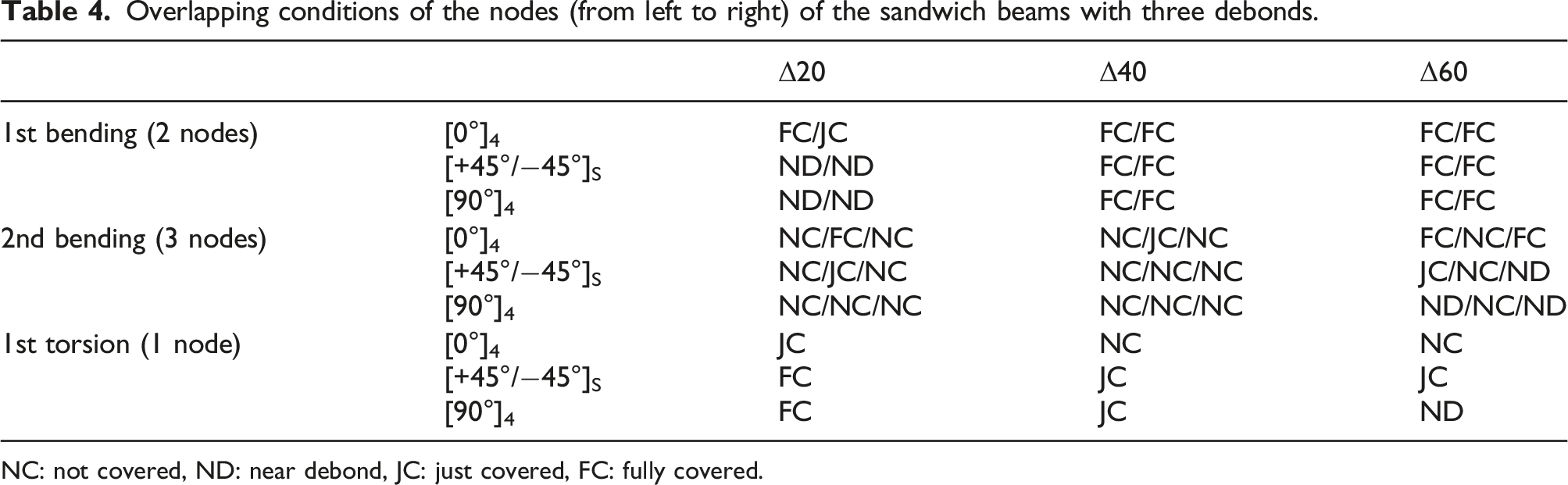
NC: not covered, ND: near debond, JC: just covered, FC: fully covered.
By investigating the overlapping conditions in Table 4, it was found that for the bending modes of the beams using [0°]4 facesheets, these nodes showed a tendency to be located closer to the debonds compared to the nodes of the beams using [+45°/−45°]S and [90°]4 facesheets. For the first bending mode of the beams with Δ20, the overlapping conditions of the two nodes of the beam using [0°]4 facesheets were FC and JC, while all of the overlapping conditions of the nodes of the beams using [+45°/−45°]S and [90°]4 facesheets were ND. For the second bending mode with Δ20, the centre node of the beam using [0°]4 facesheets was FC, that of the beam using [+45°/−45°]S facesheets was JC and that of the beam using [90°]4 facesheets was NC. Also, for the 2nd bending mode with Δ60, the left and right nodes of the beam using [0°]4 facesheets were FC, and those of the beams using [+45°/−45°]S and [90°]4 facesheets were JC or ND.
On the other hand, for the torsion modes, the nodes of the beam using [0°]4 facesheets tended to be located farther away from the debonds compared to those of the beams using [+45°/−45°]S facesheets. For example, for the first torsion mode of the beams with Δ20, the node of the beam using [0°]4 facesheets was JC, while the node of the beam using [+45°/-45°]S facesheets was FC (see Table 4).
Since overlapping between the debonds and vibration nodes results in greater reductions in natural frequencies, facesheet stacking orientations that affect the positions of vibration nodes can also have an impact on the reductions in natural frequencies. The nodes of bending modes of the beams using [0°]4 facesheets tended to be closer to or covered by the debonds, which permitted more significant relative movement between the facesheets and the core around the nodes, thus resulting in a more significant reduction in the bending stiffness. Therefore, the natural frequencies of bending modes of the beams using [0°]4 facesheets decreased more when there were debonds; in contrast, the nodes of the torsion modes of the beams using [+45°/−45°]S facesheets tended to be closer to or covered by the debonds. Therefore, the natural frequencies of the torsion modes of the beams using [+45°/−45°]S facesheets decreased more when there were debonds.
Conclusions
Sandwich structures comprising two stiff facesheets and a lightweight core are widely used. However, delamination or debonds in sandwich structures can reduce stiffness and strength, affecting the vibration behaviours of such structures. This study conducted finite element simulations to investigate the effects of three face-core interfacial debonds and facesheet stacking orientations. It was found that when the separation between the debonds was increased, the three facesheet stacking orientations ([0°]4, [+45°/−45°]S and [90°]4) show the same trend.
The most significant effect of maintaining a separation between the debonds was the location of the vibration nodes. Increasing the separation resulted in the movement of the vibration nodes. When the debonds moved and covered the nodes, there was a larger relative movement between the facesheets and the core at the regions around the nodes. A larger relative movement reduced the stiffness, resulting in greater reductions in the natural frequencies. On the other hand, if the debonds moved but did not cover the nodes, the natural frequencies increased because the relative movement was restricted.
The facesheet stacking orientation also affected the locations of the vibration nodes. For the bending modes, the nodes of the beams using [0°]4 facesheets tended to be closer to and covered by the debonds. Therefore the natural frequencies of the bending modes of the beams using [0°]4 facesheets dropped more significantly. Meanwhile, for the torsion modes, the nodes of the beams using [+45°/−45°]S facesheets tended to be closer to and covered by the debonds. Therefore the natural frequencies of the torsion modes of the beams using [+45°/−45°]S facesheets showed more significant reductions.
This study investigated how the vibration nodes and the natural frequencies of composite sandwich beams are affected by different debonding configurations and facesheet stacking orientations. In conclusion, overlapping between the debonded regions and the vibration nodes results in greater reductions in the natural frequencies.
Footnotes
Acknowledgements
The author would like to thank the National Science and Technology Council, Taiwan, for supporting this research under contract No. 112-2221-E-110-058.
Declaration of conflicting interests
The author(s) declared no potential conflicts of interest with respect to the research, authorship, and/or publication of this article.
Funding
The author(s) disclosed receipt of the following financial support for the research, authorship, and/or publication of this article: This research was funded by National Sun Yat-sen University, Taiwan, under projects No. 12DS02 and 12C030105, National Science and Technology Council, for supporting this research under contract No. 112-2221-E-110-058.