
Abstract
Honeycomb panels manufactured from wood and paper materials promote a high-value utilization of wood resources. However, the poor mechanical properties and uncommon thicknesses (32 and 40 mm) of paper honeycomb panels limit their application and promotion in the panel furniture industry. Hence, numerous attempts have been made to develop high-strength and low-density wood sandwich composites for the frames and partitions of cabinet furniture. This paper describes a method for manufacturing lightweight sandwich panels (18 mm thickness) with auxetic cores, made of fast-growing poplar. The mechanical properties of the panels and the negative Poisson's ratio of the perforated sheet cores were determined by three-point bending and uniaxial compression tests. The lower density, higher modulus of elasticity, and bending strength suggest that the developed panel is a good substitute for traditional wood-based panels. A numerical model for panels in bending tests is proposed and validated against the experimental analysis results. These investigations facilitate further research into optimizing the sandwich panel structure and its applicability in the architectural and furniture industry.
Introduction
Sandwich composites are widely used in aerospace, shipping, and construction industries because of their lightweight, high specific stiffness, high specific strength, and attractive heat insulation.1–3 Among them, honeycomb paper core laminated wood composite panels are favored by furniture manufacturers because of their lightweight, high strength, low cost, and green environmental protection.4,5 However, honeycomb paper core laminated wood composite panels show limited applicability in the construction and furniture industries owing to their low modulus of elasticity, low static flexural strength, and poor adaptability to existing furniture hardware connections based on man-made boards. 6 In particular, it cannot replace the wood-based materials commonly used in the construction industry, such as particle board, fiberboard, and plywood, for applications requiring compressive and bending components (such as furniture frames and load-bearing parts) or for flooring and partition walls of buildings. 7 Nevertheless, sandwich composites remain highly attractive in the furniture sector, and in recent years, scholars have attempted to improve their mechanical properties.8–10
As early as 1987, Lakes et al. reported a structure that exhibits a negative Poisson’s ratio effect. 11 Later, the materials with negative Poisson’s ratio were named “auxetics” or “auxetic materials” by Evans et al. 12 Auxetic materials have excellent shear resistance, 13 fracture resistance, 14 and better impact energy absorption. 15 These excellent properties have led to the use of auxetic materials in a wide range of applications, such as smart filters, 16 smart sensors, 17 medical devices, 18 and protective equipment. 19 In recent years, research into auxetic materials has also been conducted in the field of furniture, focusing on the construction of auxetic structures on a macroscopic scale. The properties of auxetics meet the requirements for materials used to manufacture furniture seating. 20 Smardzewski et al. 21 designed a compression spring based on a re-entrant hexagonal honeycomb structure for office and home furniture seating structures to improve seating comfort. Moreover, Smardzewski et al. 22 designed a physical model of a single auxetic spring to determine stiffness and durability and then physically verified and numerically modeled a seat cushion consisting of auxetic springs to determine the stiffness of the system and the distribution of surface contact pressures. Their results demonstrate that using auxetics in seating concentrates internal forces inwards, eliminating unfavorable friction and enhancing seat comfort.
The redesign of the core structure of the sandwich material is based on auxetic structures such as re-entrant models, perforated sheets models, and chiral models. The manufactured composite material not only has the advantage of high stiffness and low density but also has better shear properties, bending resistance, and impact energy absorption. Donoghue et al. 23 prepared two sets of carbon fiber laminates and found that the negative Poisson's ratio structural laminates had stronger brittle fracture resistance than conventional laminates. Smardzewski et al. 24 investigated the mechanical properties of inwardly concave hexagonal honeycomb panels, comparing them to a regular hexagonal honeycomb structure. They also explored the possibility of incorporating a tensile expansion structure into furniture sandwich composites. Additionally, Smardzewski et al. 25 conducted tests on lattice truss core composites, which consisted of polylactic acid and 40% wood flour, and demonstrated their favorable elastic properties. Moreover, Smardzewski et al. 5 developed a wooden sandwich panel using beech with an auxetic core and oval cells. The experimental results show that the developed wooden sandwich panel is a good substitute for traditional man-made boards, such as the medium-density fiberboard (MDF) and particle boards used in the construction and furniture industries. Majewski et al. 26 fabricated a double-arrow paper core with auxetics using three-dimensional (3D) printing equipment and performed analytical calculations of the stiffness and strength of the L-shaped members at the corners of furniture. The results showed that the double-arrow paper-core composite could be used as a horizontal furniture partition.
Although the manufactured composites in the above studies have ideal density and mechanical properties, their large thickness prevents widespread use in the furniture industry. A further issue that needs to be addressed is the small gluing area of the facings to the core. To address these issues, we introduced the perforated panel model into the structural design of the wooden sandwich panel. The concept of the perforated sheets model was initially introduced by Grima et al. 27 in 2010. They incorporated a specially shaped perforated structure into a conventional material with a rotationally rigid structure, showcasing unique defect behavior under tension and compression. The perforated sheets model possesses the flexibility to mimic the deformation mechanisms of concave polygonal, rotating rigid, chiral, and node-fiber structures.28–30 Currently, perforated sheet cores are utilized in the design of auxetic dowels for furniture joints.31,32 However, after reviewing the existing literature, the authors concluded that lightweight honeycomb panels incorporating perforated sheet models to create auxetic cores have neither been manufactured nor tested.
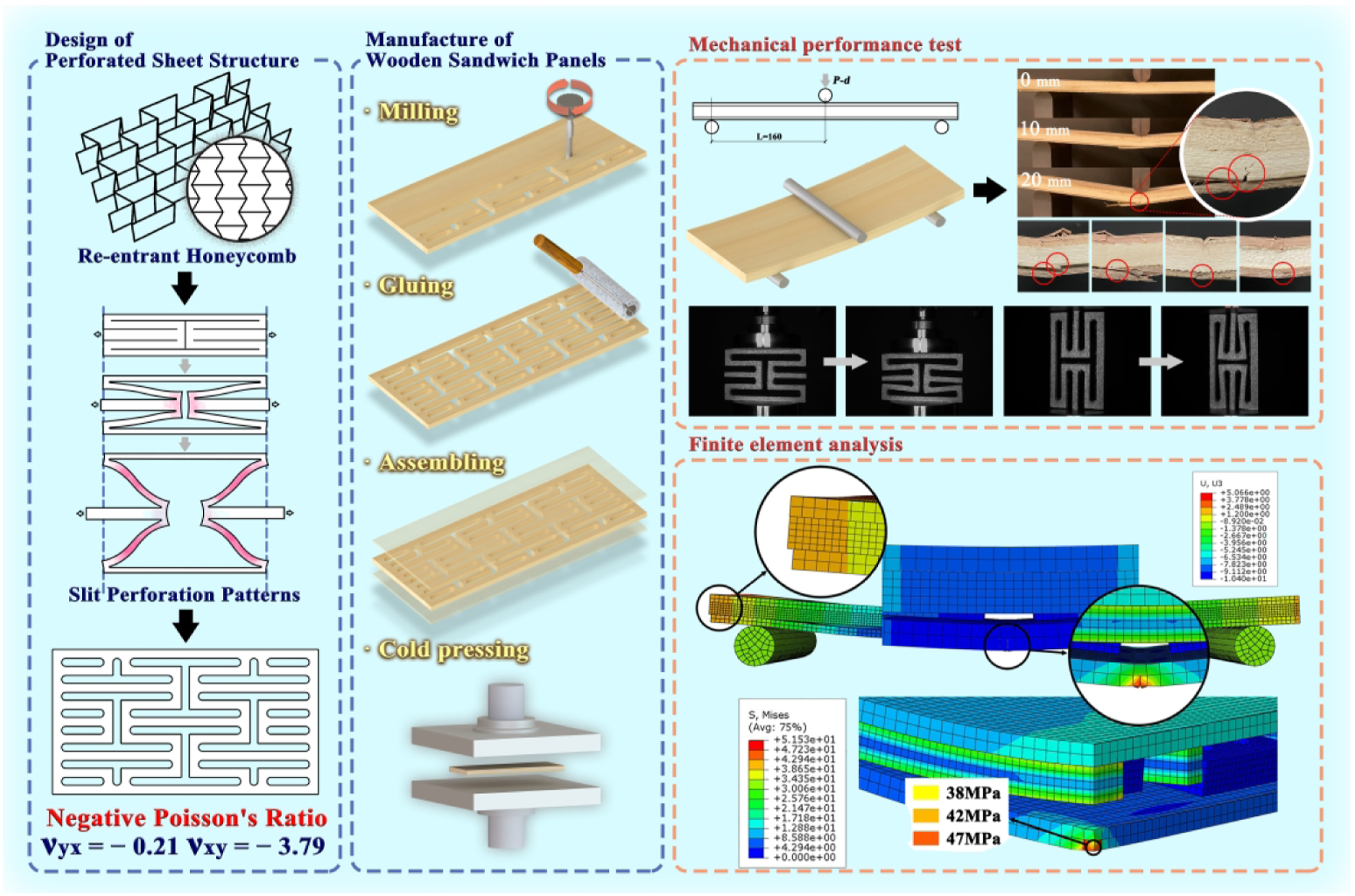
The aim of the present study was to determine the stiffness, strength, and Poisson's ratio of the core of wooden honeycomb panels. The first chapter describes the manufacturing of a new wooden sandwich panel with auxetic core. The second chapter describes the preparation of samples for tests. Three-point bending tests and uniaxial compression are described, as well as methods for determining the modulus of elasticity, bending strength, and Poisson’s ratio. The third chapter describes the numerical models of the panels used for bending tests. Finite element method (FEM) establishes predictability for the new group of sandwich panels and provides a basis for material optimization. Chapter 4 discusses the results of bending experiments and compares them with the results of numerical calculations. The core Poisson’s ratio calculated from the experimental results of compression is presented. Finally, chapter 5 provides conclusions and remarks resulting from the conducted experiments.
Materials and manufacturing
Design of core structure
The present study presents a new approach for manufacturing auxetic materials using a patterned slit perforation design (Figure 1). The re-entrant hexagonal honeycomb system (Figure 1(a)) served as the basis for the development of the perforated system (Figure 1(b)) with auxetic property. Subsequently, leading to the design of a perforated sheet core (PSC) (Figure 1(c)). Design process of the core structure: (a) re-entrant hexagonal honeycomb system, (b) perforated system, (c) PSC, (d) dimensions of PSC, where Wg is the groove width of PSC.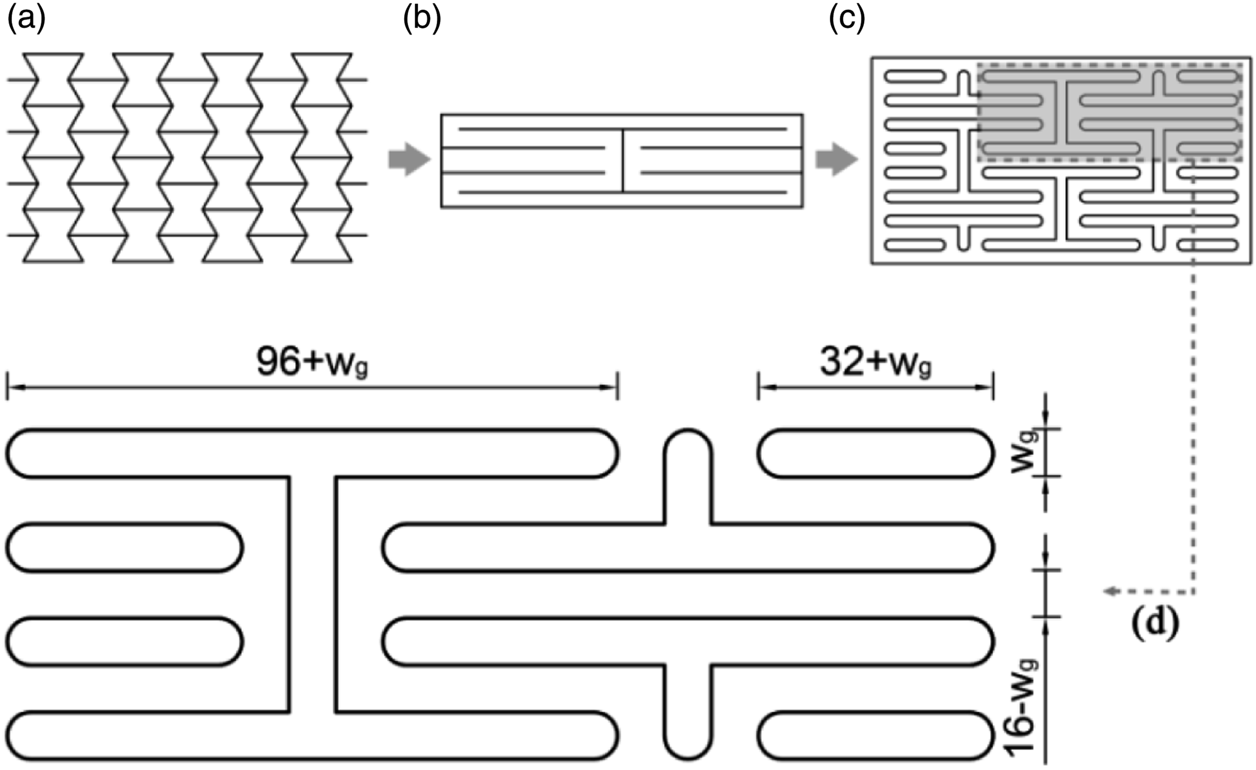
Manufacturing of auxetic wood-based sandwich panels
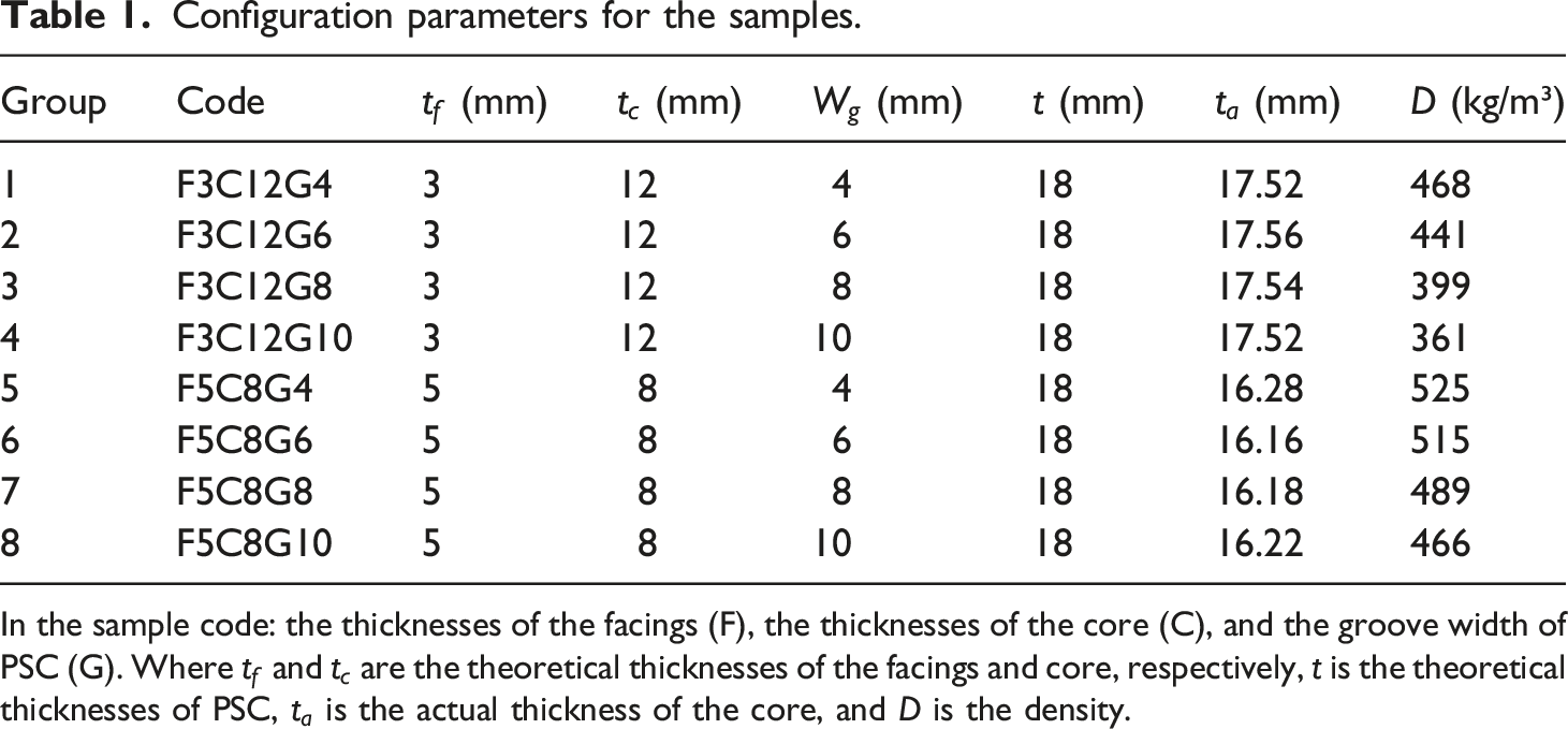
The configuration consisted of a top facing, an auxetic core, and a bottom facing. The core preparation was the first stage of the sandwich panel manufacturing process. To achieve the designed shape of the core with a perforated sheet, the panels were subjected to computer numerical control (CNC) milling on a engraving machine cutter (YK, Jinan, China) using T008 straight shank cutters and then sanded with 240 grit sandpaper. PVAc Ecotypic Latex (SKS, Fujian, China) was applied at a minimum of 100 g/m2 on the surfaces of both the facings and the core. A pressure of 0.3 MPa was applied using a 150 T universal test press for 4 h. After being glued, the panels were taken out of the press and allowed to sit in an indoor environment for 48 h. The manufacturing process of wooden sandwich panels is shown in Figure 2. All samples had a thickness of 18 mm, and the detailed configuration parameters are listed in Table 1. Manufacturing technology of wood-based sandwich panel: (a) milling of core perforated sheets, (b) application of adhesive onto the core boards, (c) assembly of veneer facings, (d) cold pressing of wood-based sandwich panels, and (e) experimental photos. Configuration parameters for the samples. In the sample code: the thicknesses of the facings (F), the thicknesses of the core (C), and the groove width of PSC (G). Where 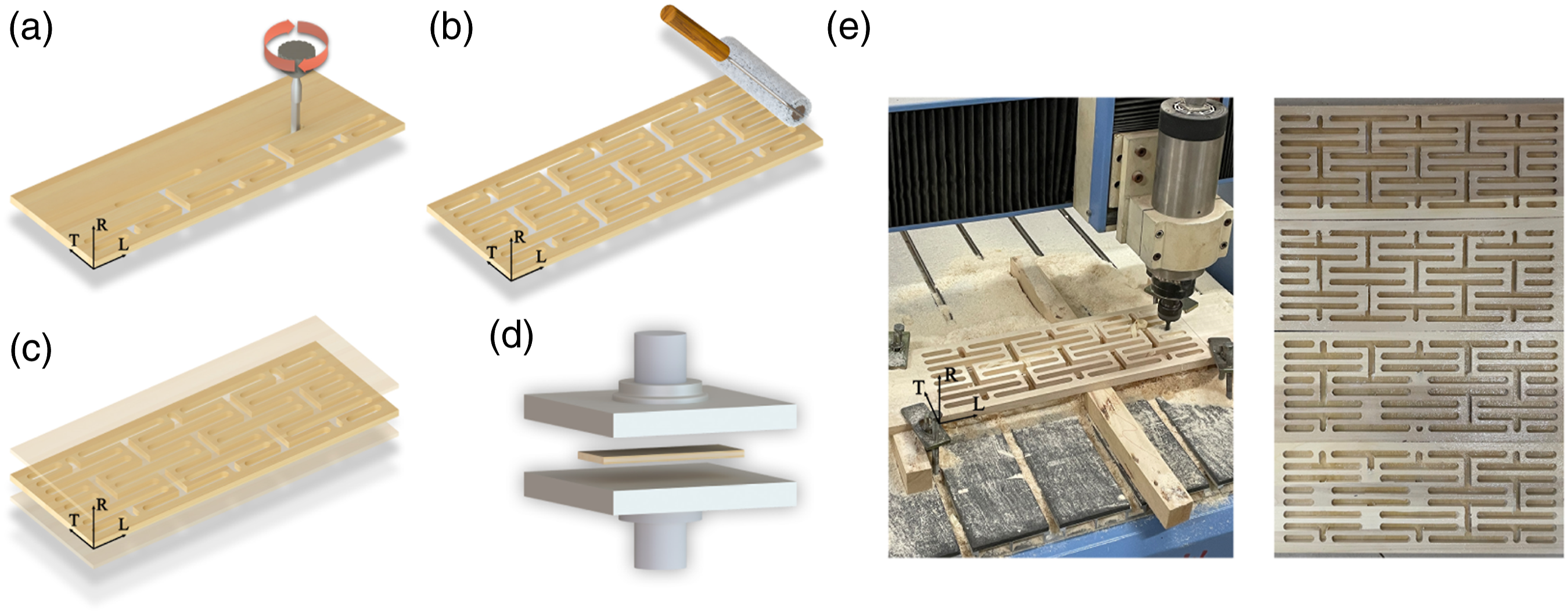
The relative density 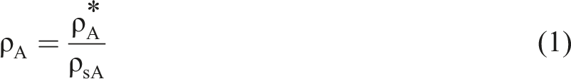
Using a perforated sheet with a 10 mm groove width as the prototype, the relative density of the core was calculated as 0.240, which is ten-fold higher than that of paper cores of honeycomb panels (0.025). However, it is 104%–125% lower than the relative density of poplar (0.490–0.540).
Properties of the constituent materials
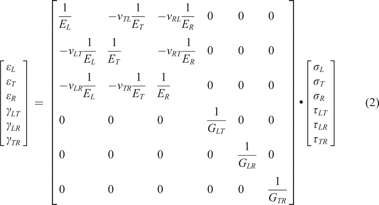
The materials used in this study included 3- and 5-mm-thick veneers, 8- and 12-mm-thick fast-growing poplar (Populus tomentosa Carrière), an adhesive based on PVAc-Ecotypic Latex (SKS, Fujian, China) for gluing the panel sets consisting of facings (glue rate 100 g/m2) and wood auxetic cores. For the measurement of elastic constants under compression, the specimen size was set to 30 × 20 × 20 mm (height × width × thickness), following the guidelines outlined in GB/T 1927.11-2022 34 and GB/T 1927.12-2021. 35 Compression specimens were prepared in various grain directions to accurately assess the elastic properties of poplar.
Experimental methods
Mechanical performance test
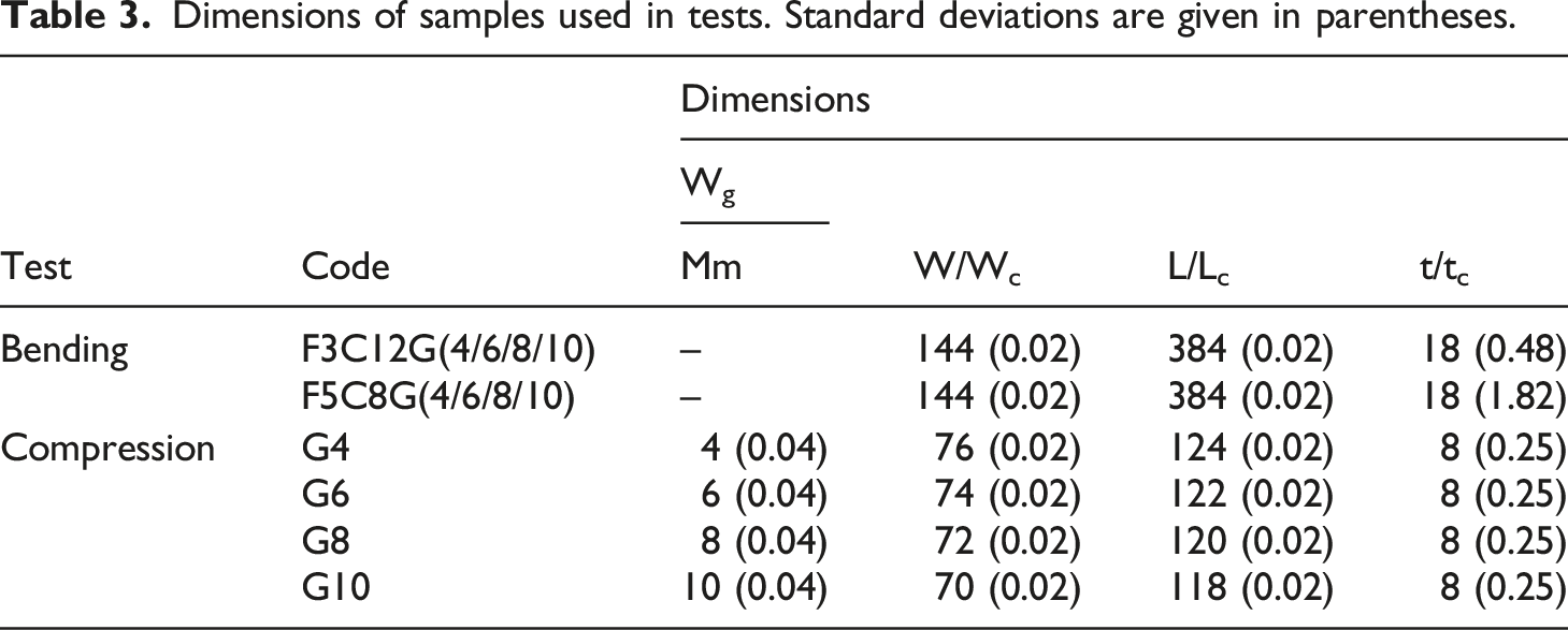
The samples for the three-point bending tests were prepared according to GB/T 17657-2022
40
(Figure 3(a)–(c)). In the three-point bending test, the loading speed was 5 mm/min. The test was interrupted when deflection of 20 mm was reached or at sample failure. Each test was performed three times to increase the reliability of the results. Uniaxial compression tests of the core were conducted to determine Poisson's ratio, which is calculated as the ratio of transverse deformation to longitudinal deformation. To perform uniaxial compression experiments, a sample was extracted from the core as the base unit (as depicted in Figure 3(d)). The force Shape and dimensions of samples used in tests: (a) sample demonstration of three-point bending, (b) theoretical model of the core, and (c) local coordinate system of the facings and core, where W and L are the width and length of the sample, respectively, (d) sample demonstration of uniaxial compression, where Wc and Lc are the width and length of the sample, respectively, and GCS and LCS represent a global coordinate system and local coordinate system, respectively. Numerical models: (e) PSC and (f) sample for the three-point bending test. Dimensions of samples used in tests. Standard deviations are given in parentheses.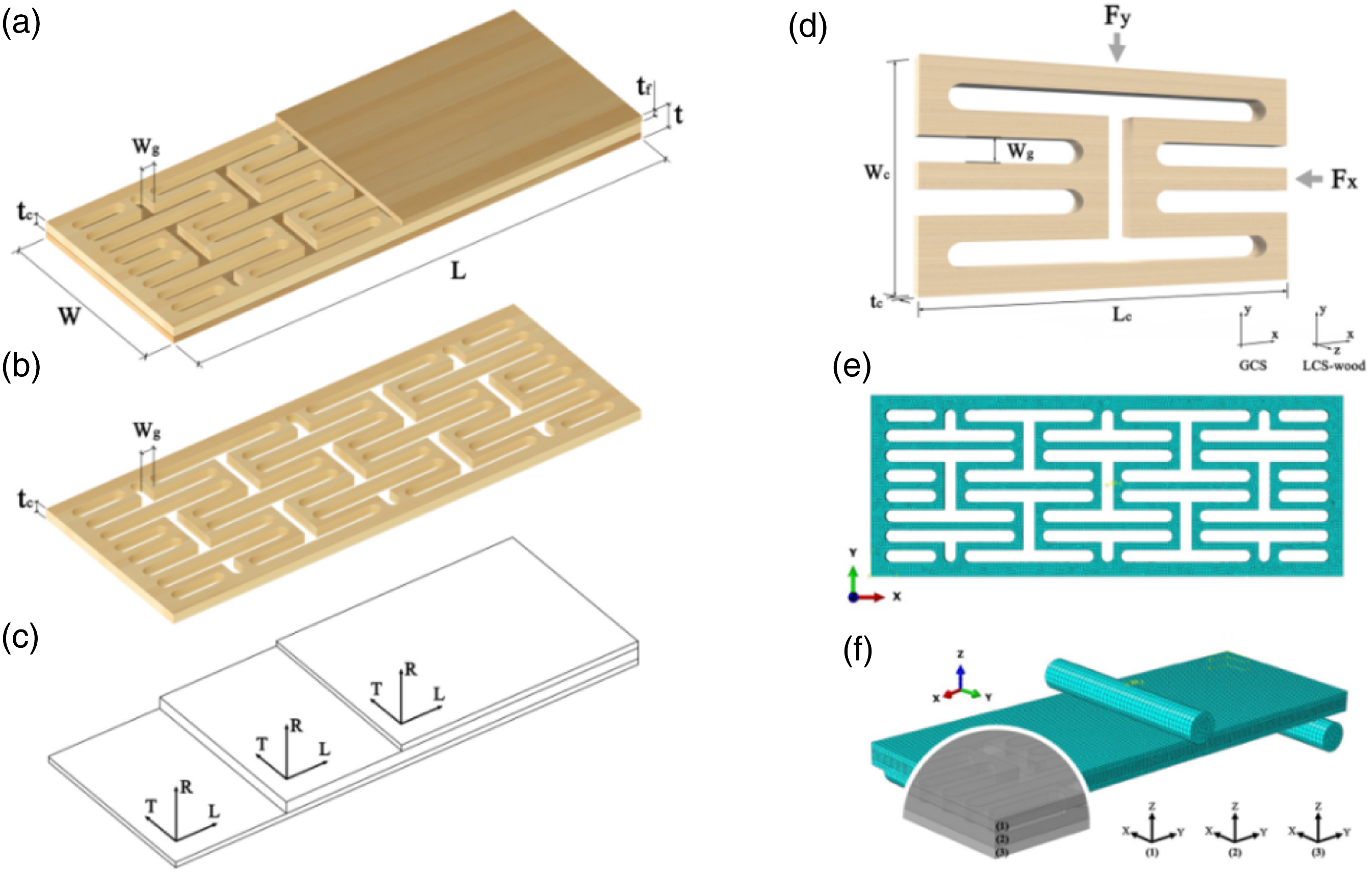
The modulus of elasticity (MOE; MPa) for the honeycomb boards is defined as
The bending strength modulus of rupture (MOR; MPa) is expressed as
The Poisson’s ratio (
Numerical model
Establishment of the finite element model
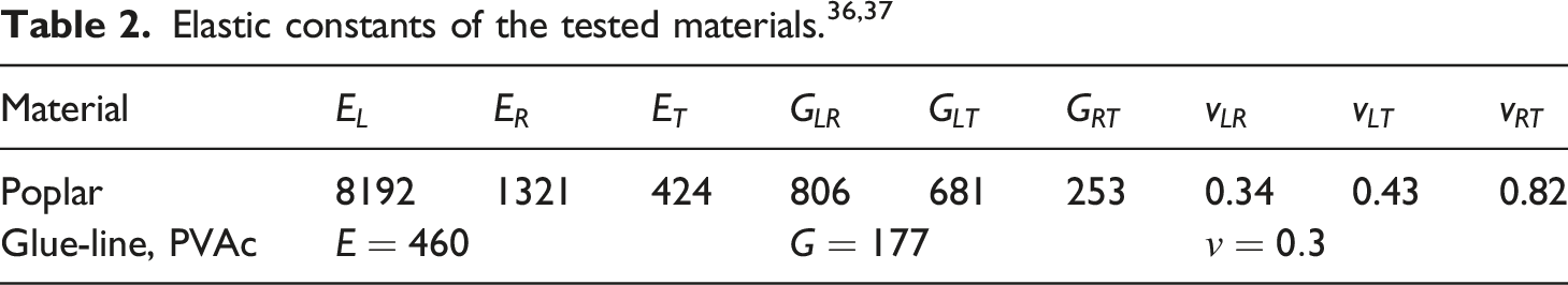
A finite element model was developed using Abaqus to simulate the three-point bending behavior of the manufactured sandwich panel. The F5C8G10 was used as an example for the three-point bending numerical model. The sample size, span length, and loading conditions were the same as those used in the experiment (Figure 3(e), (f)). The numerical model utilized in the study was described using an anisotropic plasticity material model; the material constants corresponding to the model are provided in Table 2. An extended finite element method (XFEM) was used to analyze the damage to the core and facings.41,42 Modeling of the composite layers as elastic materials was accomplished using C3D8R elements. The loading process of the universal mechanical testing machine was simulated by applying displacement in the Z-direction at the reference point and suppressing displacement in other directions. The loading fixture and support blocks were modeled from steel and have rigid body properties with an elasticity modulus of ES = 2.1 × 10⁵ MPa and a Poisson's ratio of υS = 0.3.
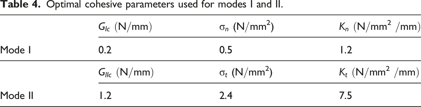
Determination of cohesive parameters
The behaviour of glue-lines can be described by a Cohesive Zone Model (CZM). The CZM was originally introduced by Barenblatt,
43
who used his model to describe the crack propagation in perfectly brittle materials. In 1976, Hillerborg et al.
44
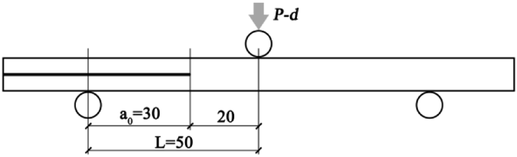
implemented CZM for the first time under the framework of FEM. In the ABAQUS program, it is possible to define t-s law introducing three values of damage initiation traction ( Schematic representations of the ENF used in fracture mode II. Optimal cohesive parameters used for modes I and II.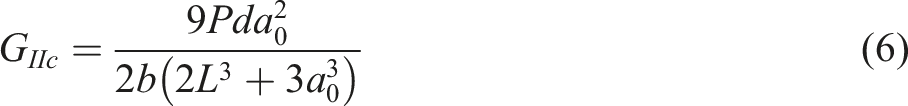
Results and discussion
Mechanical performance test
Load-deflection curve analysis
Figure 5(a) presents the load-deflection relationship for all samples of bent honeycomb panel, showing that the process of bending and deformation of the samples can be roughly divided into three stages. In the first stage, the correlation between the loading and lateral deflection is almost linear, which is the elastic deformation stage. The load increases rapidly, and the deformation is relatively small in this stage, confirming Hooke’s law.
50
Then, with a further increase in load, the sample enters the elastic-plastic stage. The deformation increase in this stage is greater than that of the loading force, and the slope of the curve gradually decreases. Upon reaching the maximum load, the sample enters the crushing stage of the surface plate, and subsequently, the load gradually diminishes after reaching the peak value. Analysis of three-point bending test results: (a) dependence of force on deflection for all samples subjected to three-point bending, (b) characteristic failure of bent sandwich panels, and (c) examples of the damage of bent sandwich panels.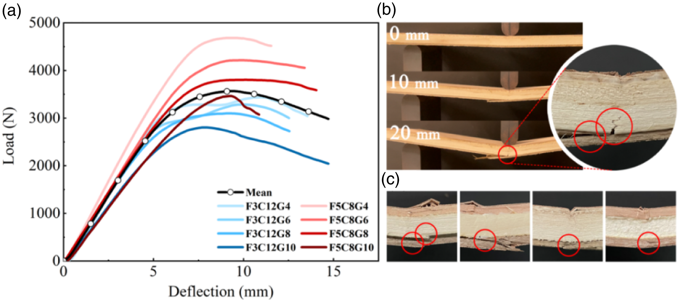
Figure 5(c) illustrates the typical damage patterns observed in the sandwich panel. These patterns correspond to the damage observed in samples F3C12G8 and F5C8G8, which exhibit stiffness characteristics closest to the mean curve. Initial cracks appeared in the bottom facings. The damage to the bottom facing subsequently results in the failure of the glue interface between the bottom facing and core, leading to the destruction of the core (as depicted in Figure 5(b)).
Effect of thickness configuration on the failure load of the perforated sheet core
Two thickness configurations were set up for this study, namely, one with a facing thickness of 3 mm and a core thickness of 12 mm (F3C12G4, F3C12G6, F3C12G8, and F3C12G10) and the other with a facing thickness of 5 mm and core thickness of 8 mm (F5C8G4, F5C8G6, F5C8G8, and F5C8G10). Figure 5(a) shows that the failure loads for the F5C8 group were greater than those for the F3C12 group. Therefore, when the overall thickness of the honeycomb panel is constant, the failure load increases with increasing face thickness.
Effect of milling volume on the failure load
The cores were milled to achieve a lighter weight, and the groove widths of the four-degree species (4, 6, 8, and 10 mm) were set up. The relationship between milling volume and failure load was plotted (Figure 6(a)). Samples F3C12G4, F3C12G6, F3C12G8, and F3C12G10 show that the slope of the milling volume curve during the increase phase is notably steeper compared to the slope of the failure load curve during the decrease phase. For example, the milling volume in samples F3C12G4 and F3C12G6 increased by 65.5%, whereas the failure load decreased by only 4.4%. Moreover, the milling volumes of the samples increased by 65.5%, 73.7%, and 78.6%, respectively, compared to the previous sample; however, the failure loads decreased by 4.4%, 5.6%, and 9.6%, respectively. Similar trends were observed for F5C8G4, F5C8G6, F5C8G8, and F5C8G10. The milling volumes of these samples increased by 65.5%, 73.7%, and 78.6%, respectively, compared to the previous sample; however, the failure loads decreased by as little as 10.0%, 9.8%, and 9.0%, respectively. Considering the density and strength of the material, F5C8G10 exhibits the optimal combination of facings and core. (a) Relationship between the failure load and milling volume, (b) A comparison of 
Comparison with the properties of conventional wood-based materials
To emphasize the advantages of the manufactured sandwich panel, denoted as 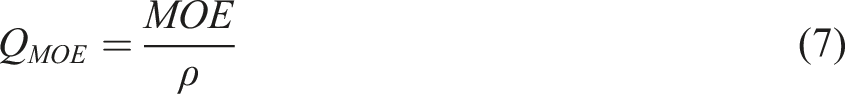
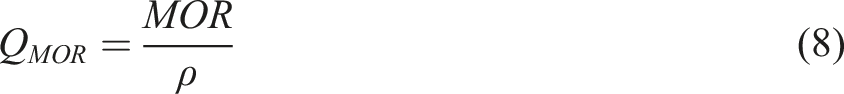
As shown in Figure 6(b), the
Similar trends were observed for the calculated
Uniaxial compression
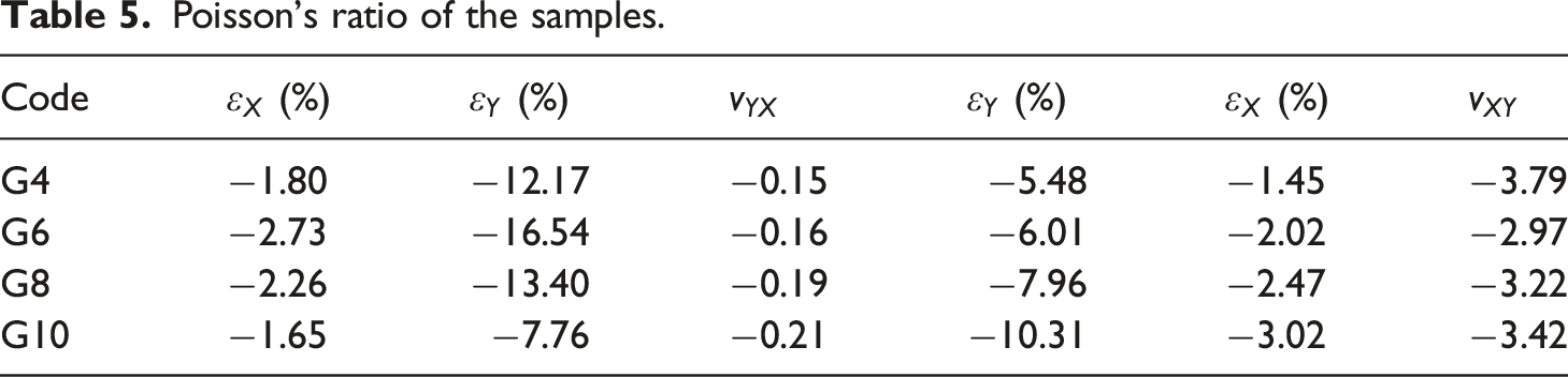
The measurements of the samples’ deformation were made with the use of digital image analysis. The (a) Image of sample before Y-axis compression, (b) Image of sample after Y-axis compression, (c) Image of sample before X-axis compression, and (d) Image of sample after X-axis compression. Poisson’s ratio of the samples.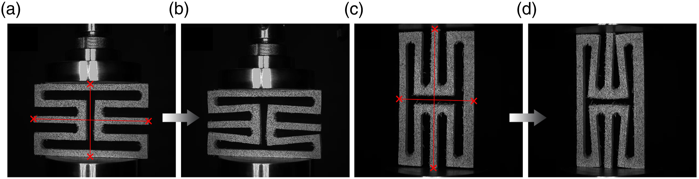
Numerical model analyses
Numerical analysis of wood's mechanical properties serves as the foundation for conducting finite element analysis (FEA) on wooden sandwich panels. The load-displacement curves for the three principal axes of poplar under compression were obtained using the data processing function of Abaqus. The results were compared with test data (Figure 8), demonstrating that the trend of the curve from the FEA is in good agreement with the experiment. When the deflection exceeds a certain threshold (>8 mm) or during the damage phase, the software terminates the calculations owing to stress singularities. In furniture design, the yield strength of the material is typically used as the permissible stress. Therefore, the finite element model is suitable for predicting the mechanical behavior of poplar in elastic and initial plastic phases. Comparison between FEM and experiment in three-grain orientations under compression. (a) L-axis direction, (b) R-axis direction, (c) T-axis direction.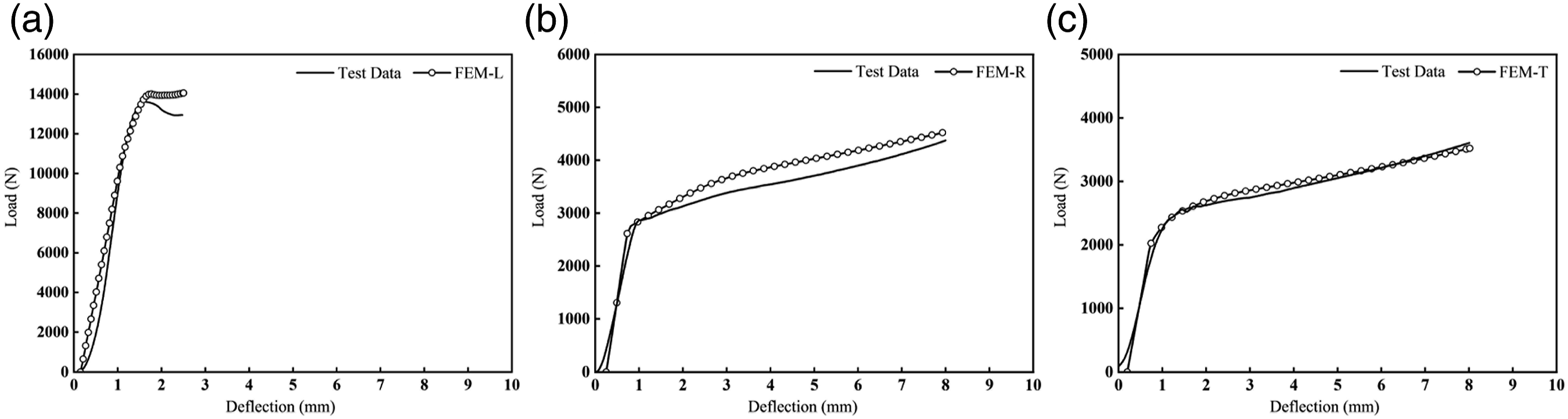
The numerical simulation of the optimal solution, F5C8G10, was performed using displacement control until the specimen reached failure, allowing the bending force to be calculated. A comparison between the FEM and experimental results was conducted using a three-point bending test (Figure 9(a)). The model exhibited a reasonable level of accuracy in predicting the bending force of the sandwich panel. This data shows that the experimentally established force at sample failure, Fmax = 3462 N, is only 5.8% lower than the value calculated in the numerical analysis. The numerical value at failure (8.23 mm) was slightly lower than the mean experimental value for F5C8G10 (9.35 mm). We can observe that the general trend of the FEM curves agrees with the experimental curves, but there are differences in the damage phase. After reaching the maximum load (A, A'), the rate of load drop in FEM is significantly larger than that in experiment. The reason is that the cohesive units are deleted after the maximum stress is reached, resulting in an instantaneous decrease in strength. However, after the wood is locally destroyed, there are still connections between wood fibers in experiment. Comparison of FEM and experiment for the three-point bending test of F5C8G10. Examples of deflections (b), cracks (c) and core (d) in the multilayer beam.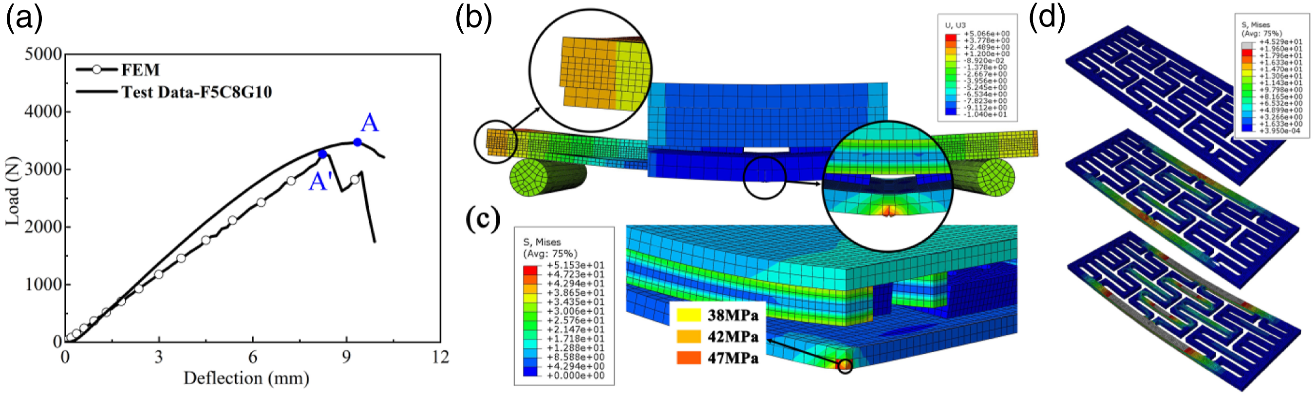
Figure 9(b) shows the deformation and damage patterns of the panels and cores in the three-point bending experiments. The maximum stress is concentrated in the region of force loading, and the damage to the panel primarily occurs at the bottom surface. From a qualitative perspective, the predicted numerical failure mode is similar to the experimental failure mode. Notably, fracture occurs in the bottom panel during loading and propagates to the upper part, where the adhesive fails under a combination of normal and shear stresses. As shown in Figure 9(c), the stresses in the crack gap cells of the face ranged from 33 to 47 MPa at the point of damage, which is in good agreement with the bending strength of the sandwich panel (43.9 MPa, Figure 6(c)). Comparing the stress distribution of the edge and the core in Figure 9(d), it can be seen that the core exhibits a more advantageous capacity to transfer external loads.
Conclusions
A technology was developed to manufacture wooden sandwich panels with auxetic cores. The designed wooden sandwich panels have a high modulus of elasticity, bending strength, and a desirable density (<400 kg/m3) while avoiding the use of large amounts of adhesives. Importantly, the panel thickness of 18 mm is widely used in the manufacturing of panel furniture, making it a viable alternative to the commonly used traditional fiber and particle boards, especially for use as frames and partitions in cabinet furniture. Compression test results confirm the auxetic properties of perforated sheet cores. As the groove width of inclusions increases, the Poisson’s ratio
Footnotes
Declaration of conflicting interests
The author(s) declared no potential conflicts of interest with respect to the research, authorship, and/or publication of this article.
Funding
The author(s) disclosed receipt of the following financial support for the research, authorship, and/or publication of this article: This work was supported by the Hunan Province Key R&D (2022NK2043), the Hebei Province Scientific Research Project for the Introduction of National High-level Innovative Talents (2021HBQZYCXY011), the Hunan Provincial Science and Technology Innovation Leaders (2021RC4033), and the Young and middle-aged scholars training program (2020TJ-Q18).