
Abstract
Reacting flow simulations for combustion applications require extensive computing capabilities. Leveraging the AMReX library, the Pele suite of combustion simulation tools targets the largest supercomputers available and future exascale machines. We introduce PeleC, the compressible solver in the Pele suite, and detail its capabilities, including complex geometry representation, chemistry integration, and discretization. We present a comparison of development efforts using both OpenACC and AMReX’s C++ performance portability framework for execution on multiple GPU architectures. We discuss relevant details that have allowed PeleC to achieve high performance and scalability. PeleC’s performance characteristics are measured through relevant simulations on multiple supercomputers. The success of PeleC’s design for exascale is exhibited through demonstration of a 160 billion cell simulation and weak scaling onto 100% of Summit, an NVIDIA-based GPU supercomputer at Oak Ridge National Laboratory. Our results provide confidence that PeleC will enable future combustion science simulations with unprecedented fidelity.
Keywords
1. Introduction
High-fidelity simulations of turbulent combustion at the exascale will play a major role in the development of predictive models for design of efficient, clean engines. Combustion simulations incorporating detailed kinetic mechanisms describing multi-component fuel chemistry in relevant parameter regimes along with multi-physics phenomena (i.e., spray, soot and thermal radiation) in complex flow configurations will provide unprecedented insight into details about physical and chemical processes in engines. For example, simulations will inform fuel–air mixture formation injection strategies tailored to ensure optimal ignition timing and combustion rates while minimizing emissions inside of a heavy-duty freight vehicle or ship engine. They will also inform fueling rates, placement, and strength of ignition sources relevant to flame-holding, for example, in a scramjet engine. Insights derived from simulations will also improve the performance of combustion technologies such as stationary gas turbine engines that accommodate fuel and load flexibility (e.g., carbon-free energy carriers such as hydrogen and ammonia blends).
The Pele suite of combustion application codes, developed under the United States’ Exascale Computing Project (ECP), seeks to provide combustion modeling capabilities that tackle these areas, among others. PeleC and PeleLM, the two primary applications within the Pele suite, feature the use of block-structured adaptive mesh refinement, arbitrary geometries, an extensible set of combustion models, and non-ideal equations of state. They solve the reacting Navier–Stokes equations in the compressible and low Mach regimes, respectively. Each of the two codes links to PelePhysics, a library of models for thermodynamics, transport, and reaction chemistry. In addition, PeleMP provides access to multi-physics extensions that plug into both the compressible and low Mach formulations, including Lagrangian particle-based multi-phase models to represent fuel sprays, and soot and thermal radiation transport. Both PeleC and PeleLM are the outgrowth of over 20 years of development in adaptive mesh incompressible and reacting flow simulation algorithms (Almgren et al., 1998, 2010; Day and Bell, 2000; Nonaka et al., 2012, 2018; Rendleman et al., 1998). The suite implements many modern software development practices, for example, automatically generated documentation, releases via GitHub, continuous integration (CI), nightly testing dashboards, static analysis, memory checking, post-processing tools, and tutorials.
This work focuses on software contributions in the development of PeleC for graphics processing unit (GPU) hardware with an emphasis on performance portability beyond NVIDIA GPUs. Additionally, we discuss performance test cases on pre-exascale machines, associated metrics, and scaling results in high performance computing (HPC) environments.
2. Description of the PeleC software
PeleC, which has been used for simulations of direct fuel injection in a supersonic cavity flame-holder (Sitaraman et al., 2021b), Figure 1, leverages the AMReX (Katz et al., 2020; Zhang et al., 2019, 2021) adaptive mesh refinement (AMR) library for meshing infrastructure, including grid refinement, distributed parallelism, geometry representation, and output. Although the AMReX library has been extensively documented in the supplied references, we briefly recall the relevant concepts pertinent to this work. Grids in AMReX are represented with Boxes; each Box defines the extents in a global index space of a data container known as a FAB. A FAB contains a chunk of contiguous memory used to hold field data that is associated with a Box. The data in a single FAB can be viewed as a single multi-component array and, while the individual Boxes do not overlap, the data in the FABs may overlap due to ghost cells. A collection of FABs are managed as a MultiFab, which includes tools to manage overlapping “grow” cells to simplify stencil-type computations. Typically, the state data at each AMR level in an AMReX calculation is stored in MultiFabs. This data structure is distributed, at the granularity of a FAB, across processing units on a distributed memory computing platform. A MultiFab iterator, Simulation of direct fuel injection in a supersonic cavity flame-holder using PeleC (Sitaraman et al., 2021a,b).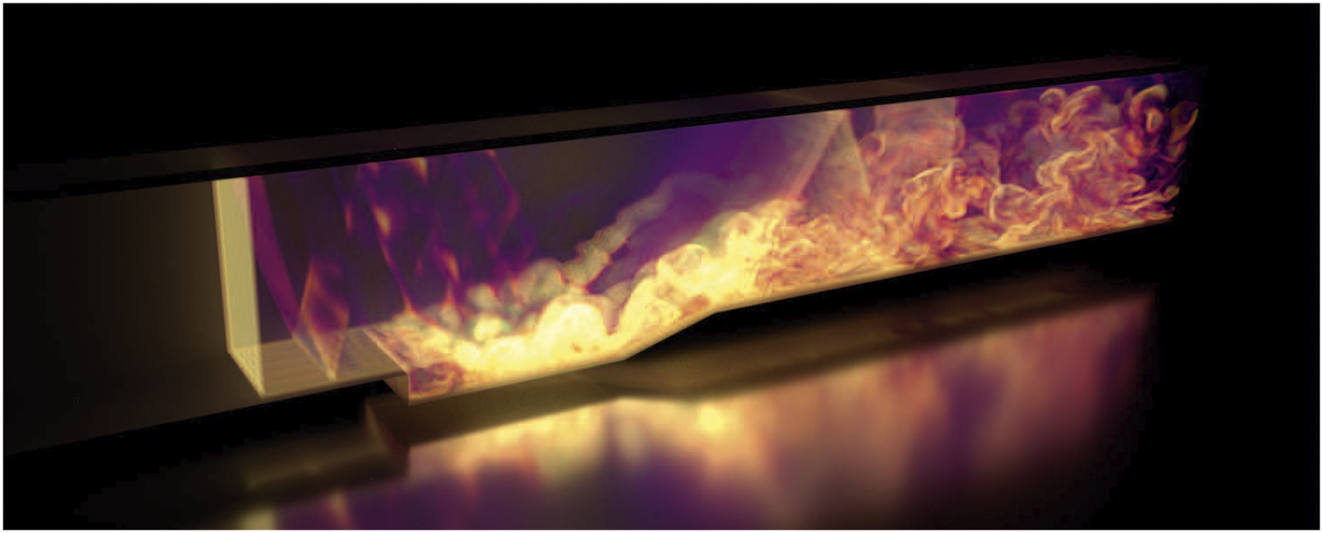
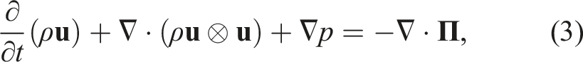
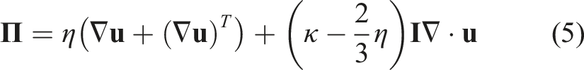
PeleC solves the conservation equations for mass, species mass fractions, momentum, and energy with a finite rate evaluation of chemistry in the compressible flow regime
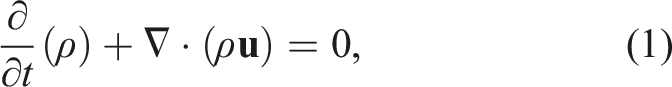
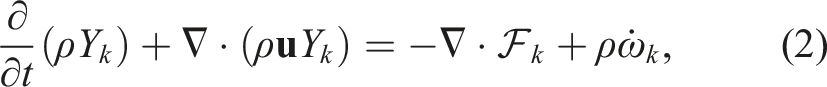

Finite-rate chemistry integration is performed through the PelePhysics library, which includes a Python-based translator (Emmett et al., 2014; Sitaraman and Grout, 2017) called FUEGO that converts combustion models expressed in the CHEMKIN (Kee et al., 1989) format into loop-unrolled C++ code for rate evaluations. As will be discussed in Section 4, chemistry integration is typically the most time-consuming routine in PeleC and has been the focus of many optimization efforts. The computational cost of this facet depends strongly on the complexity of the chemistry (number of species and reactions) as well as the inherent numerical stiffness of the chemical timescales relative to the size of PeleC’s time step. As a result, the choice of the ordinary differential equation (ODE) integrator used to compute the chemical source term at a single coupled step is critical.
The system of partial differential equations (1)–(4) is spatially discretized using a second-order finite volume approach. Two different discretizations are supported in PeleC to compute the hyperbolic fluxes: unsplit piecewise parabolic method (PPM) (Colella and Woodward 1984), with optional hybrid PPM WENO variants (Motheau and Wakefield, 2020), and a second-order characteristic-based spatial method coupled with a Runge–Kutta time integration (i.e., a method of lines (MOL) approach). The diffusion fluxes are discretized in space with second-order centered differences. Transport coefficients are computed at cell centers from the evolving state data and harmonically averaged to cell faces. PeleC supports two options for coupling the physical processes over the numerical time step: A standard predictor–corrector approach with (optional) fixed point iteration to tightly couple stiff chemistry and transport or an iteratively coupled scheme based on a spectral deferred correction approach (Nonaka et al., 2018).
An embedded boundary (EB) formulation (Pember et al., 1995) is used to represent complex geometries. This method allows for the determination of correct local normal fluxes at faces generated by “cut-cells” for geometric features that do not align along Cartesian coordinate directions, represented in Figure 2. AMReX provides the necessary EB data structures, including volume and area fractions, shown in Figure 2(a), surface normals and centroids, and local connectivity information. Fluxes in each cut cell are the usual fluxes through the faces, multiplied appropriately by the face areas, with the addition of the flux through the EB, shown in Figure 2(b). A state redistribution methodology (Berger and Giuliani, 2021; Giuliani et al., 2022) is implemented to circumvent numerical instabilities regarding small cut cells, illustrated in Figure 2(c). This is achieved through the use of a linearity preserving, conservative, and accuracy preserving redistribution scheme of state quantities in the neighborhood of each cut cell. The algorithm consists of (i) temporarily merging each cut cell into potentially overlapping neighborhoods of cells, (ii) computing a stabilized value that preserves conservation and accuracy using a weighted convex sum of the solution in the neighborhoods, and (iii) replacing the cut cell state with this stabilized state. This redistribution scheme is available through the AMReX-Hydro (Almgren, 2022) library. Currently, EB simulations require the use of the MOL numerical scheme for the transport fluxes, which is generally faster, but is both less accurate and requires a smaller time step than the PPM option typically preferred for non-EB cases. EB representation of cut cell geometry in 2D. The gray region is excluded from the calculation. Figures reproduced from AMReX Team (2022). (a) Face areas, A and volume, V, (b) regular fluxes, F, and EB fluxes, FEB, and (c) mass redistribution from cut cell (red) to neighbor cells.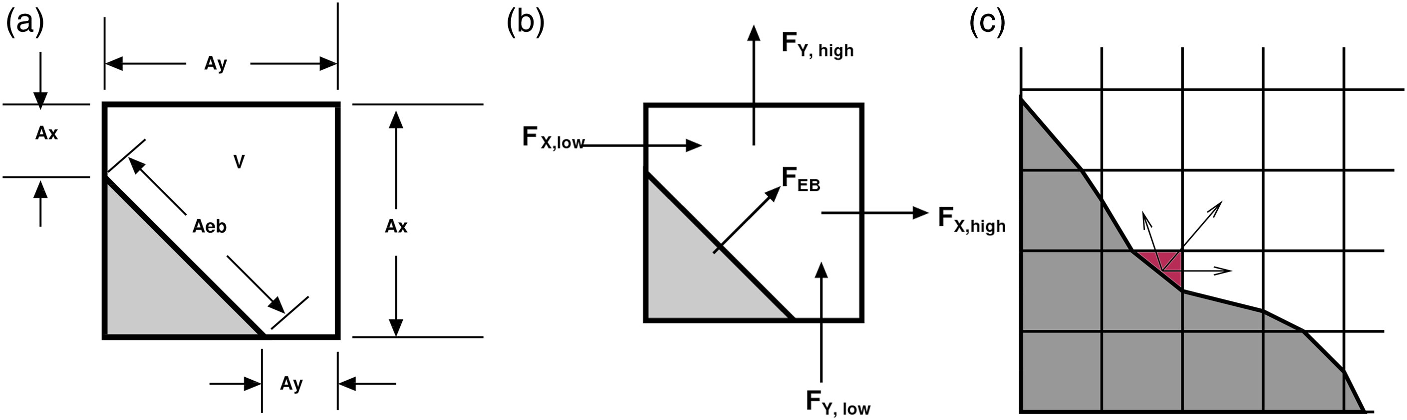
PeleC uses estimates of the computational expense within each cell to inform load balancing in distributed systems. AMReX manages load balancing using a space-filling Z-Morton curve to enumerate the grids based on the assigned computational weights. The resulting ordering is then partitioned evenly across distributed processes. AMReX also implements the Message Passing Interface (MPI) communication in distributed systems and is actively being optimized for future systems. Aggregation is used whenever possible to minimize the number of messages between pairs of MPI ranks.
An extensive verification and validation study has been performed to ensure correctness of PeleC results. The Method of Manufactured Solutions (MMS) (Roache, 2002), implemented through the MASA library (Malaya et al., 2012), is used to formally verify second-order accuracy for the fluid transport operators. Validation of PeleC was performed using standard benchmark cases, including the decay of homogeneous isotropic turbulence, non-reacting and reacting Taylor–Green vortex breakdown, a counter flow diffusion flame, and an unstretched pre-mixed flame (PMF). Verification and validation simulations exercising the EB capability include, amongst others, a MMS convergence test, ignition within complex geometries, and multispecies shock tubes at an incline with respect to the AMR mesh.
PeleC also leverages other libraries. Most notably, SUNDIALS (Hindmarsh et al., 2005), which is a library of solvers for nonlinear and differential/algebraic equation systems. PeleC uses git submodules to track specific versions of the necessary libraries to ensure that users have a consistent and compatible software stack. PeleC is publicly available at the software’s GitHub repository, https://github.com/AMReX-Combustion/PeleC.
3. Software engineering for HPC performance portability
At the inception of the PeleC project, the target computing architecture was the Intel Xeon Phi processor, which resembled previous x86 central processing units (CPUs), but included wider SIMD lanes, a tiled architecture, and on-die high-bandwidth memory. These characteristics made it amenable to many existing programming models. Early development of AMR software libraries such as SAMRAI (Wissink et al., 2001), BoxLib (BoxLib Team, 2018; Zhang et al., 2016), PARAMESH (MacNeice et al., 1999), and FLASH (Fryxell et al., 2000) were written (at least partially) in Fortran due to its reputation for aggressive compiler optimization. Over time, some of these libraries suggested overall application orchestration be done in C++ while the computational kernels continued in Fortran. Therefore, PeleC development originally used this design. As the Xeon Phi was discontinued, the first exascale machines became focused on GPU architectures in the United States, notably with initial offerings from Intel, AMD, and NVIDIA providing the GPU accelerators. To address this evolution in target architecture, PeleC development experimented with porting the main components of the code to both the OpenACC programming model and AMReX’s C++ framework for performance portability. PeleC’s current design targets both GPU architectures and CPUs by utilizing AMReX’s framework. We note that other AMReX codes are following a similar path as PeleC (Katz et al., 2020), and this work seeks to continue sharing lessons learned, albeit for different physical domains. In this section, we first describe the original PeleC programming model tailored toward CPU performance and then discuss our initial port using the OpenACC programming model for accelerated hardware and finally the use of the new C++ programming model provided by AMReX.
3.1. Original PeleC programming model for CPUs
In the original PeleC implementation, C++ orchestration routines called Fortran kernels that preferred “lowered loops” which focused on vectorization in a single spatial direction by performing a minimal variety of operations in each inner loop. Since the interface between C++ and Fortran happened at each kernel through the routine arguments, duplicate Fortran kernels were required for 1D, 2D, and 3D support such as in the hydrodynamic and diffusion fluxes. Additionally, many of these kernels had time-consuming operations, that is, rate evaluations in PelePhysics, which were C functions. Therefore, the code had C++ functions calling Fortran functions, which then called C functions. This mixed language regime posed difficulties which will be discussed in later sections.
#pragma omp parallel for (amrex:: const amrex::Box& box = mfi.tilebox(); amrex::Array4<amrex::Real const> const& u = U. ↪const_array(mfi); amrex::Array4<amrex::Real> const& f = F.array( ↪mfi); kernel(box, u, f); // Fortran kernel that can ↪include C calls } The initial development for PeleC targeted addition of an X+Y parallel execution model (from merely X at its inception) where X is an inter-nodal communication model. In this work, X is the MPI and Y is an intra-nodal parallel programming model (e.g., OpenMP) based on multiple threads of computation with shared memory access to the data within that rank. The objective of this hybrid model is to enable additional parallelism while avoiding increased metadata usage. When the AMReX library introduced this hybrid model, PeleC operations were adapted to a framework more explicitly aware of work distribution. This effort specifically focused on an MPI+OpenMP model. This model uses logical tiling, or cache blocking, to modify loops to improve data locality (Unat et al., 2013) and parallel work distribution in a multi-threaded shared memory environment. AMReX provides data accessors and optional arguments to After implementation of this model, small speedups were observed (approximately 10%) by trading ranks for a small number of threads (typically 2 or 4 threads per rank for Intel Xeon Phi and Haswell systems) when using large numbers of ranks (on the order of 200k–500k). On the Intel Xeon Phi system tested in this work, when less than around 200k MPI ranks were necessary for a simulation, we found that a flat-MPI arrangement was typically sufficient for performance while avoiding increased complexity of process mappings at runtime.
3.2. OpenACC programming model for PeleC on CPUs and GPUs
When the Intel Xeon Phi processor was discontinued, GPUs became the de facto architecture for exascale in the United States (while CPU-based approaches to exascale are also viable, e.g., the Fugaku supercomputer in Japan (Fujitsu, 2022)). With PeleC’s original programming model a mix of C++, Fortran, and C, an effort was made to avoid rewriting all of PeleC’s kernels in another language, while still allowing execution on the GPU. At the time of this work, OpenACC was the most mature pragma-based GPU offloading model for Fortran and was chosen to explore offloading with minimal code changes. OpenMP 4 introduced accelerator support around 2013, but it was not well supported by many compilers until much later (Larkin, 2018). Using OpenACC also made it unnecessary to modify the existing OpenMP pragmas in PeleC which kept the MPI+OpenMP model intact.
Profiling showed that 90% of PeleC’s runtime was under a single advance routine that contained five routines requiring GPU parallelization. Within those five routines, there were around 50 small routines that needed to be labeled as device routines, or seq in OpenACC. Most of these routines are generated from the FUEGO chemistry code generator. This required creation of a version of FUEGO which emits Fortran rather than C code.
Chemistry integration also required execution on the device. The original chemistry integrator was based on DVODE, an implicit time step integrator (Hindmarsh, 1983). It was written in Fortran and contained numerous logic statements not suited for GPU accelerators. Therefore, an explicit 6-stage 4th-order Runge–Kutta (RK) integrator (RK64) with an embedded error estimator for time step adaption (Kennedy et al., 2000) was specifically written with GPU performance in mind. This integrator reduced CPU performance for stiff reaction mechanisms where a large number of sub-iterations were necessary to ensure stability, making it the costliest facet of PeleC.
for (amrex:: const amrex::Box& bx = mfi.tilebox(); amrex::FArrayBox& fab = mf[mfi]; plusone_acc(BL_TO_FORTRAN_BOX(tbx), ↪BL_TO_FORTRAN_ANYD(fab)); subroutine plusone_acc() ! arguments omitted !$acc parallel loop gang vector collapse(3) ↪default(present) do k = lo3, hi3 do j = lo2, hi2 do i = lo1, hi1 data(i,j,k) = data(i,j,k) + 1.0d call deep_nest_of_functions() end do end do end do !&acc end parallel loop end subroutine plusone_acc Concurrently with these efforts, AMReX’s C++ framework was being developed, discussed in Section 3.3, and allowed us to leverage its memory-pool manager (AMReX Team, 2022) instead of explicitly managing the memory for the kernels in OpenACC. For most kernels, we were able to use the default(present) statement in OpenACC which assumed data existed on the device for all pointers in the kernel. These OpenACC development efforts resulted in code structured as in Listing 2. The statement acc parallel loop gang vector collapse(3) is used to offload the kernel calculation of a single FAB onto the entire device, targeting one thread per cell. Since single FABs are sometimes not big enough to saturate an entire GPU device, concurrent kernel execution was deployed to compute multiple boxes simultaneously on a device. This was achieved through the use of NVIDIA’s multi-process server (MPS) utility. MPS allows multiple MPI ranks to share a single GPU device simultaneously, which increased utilization of the GPU. On Summit (described in Section 4.1.1), PeleC used MPS with seven MPI ranks per V100 GPU on a node. As stated earlier, AMReX’s C++ performance portability framework was progressing in development alongside our OpenACC work. Use of this C++ framework was also being prototyped in PeleC. In Figure 3, we show the performance results for a weak scaling test on Summit using both prototypes. We see that both prototypes were able to provide similar performance. However, much of the same functionality was being used for each prototype. Namely, they shared similar data management, both were using concurrent kernel execution methods (discussed in Section 3.3 for C++), and both methods launched kernels for boxes over the entire device. After observing these results, it was apparent one could achieve similar performance on the GPU in both the OpenACC and C++ models. Nevertheless, once the OpenACC prototype was in place, several drawbacks for keeping Fortran code in PeleC became evident: Compiler support was lacking, and GPU support beyond existing hardware was unclear. Supporting mixed languages was also a barrier because of increased debugging difficulty, increased difficulty for the compiler to perform optimizations, and reduced support across the toolchain. With the single language C++ prototype achieving similar performance, these reasons motivated the decision to move PeleC to AMReX’s C++ model. In summary, the main benefits of OpenACC were that it required minimal changes to the code and it could provide similar performance to the C++ programming model which compiled kernels with NVIDIA’s CUDA language in this case. Comparison of weak scaling for different programming models on Summit for the PMF problem, defined in Section 4.2.1. 223 cells per (218 million DoF) node and no AMR.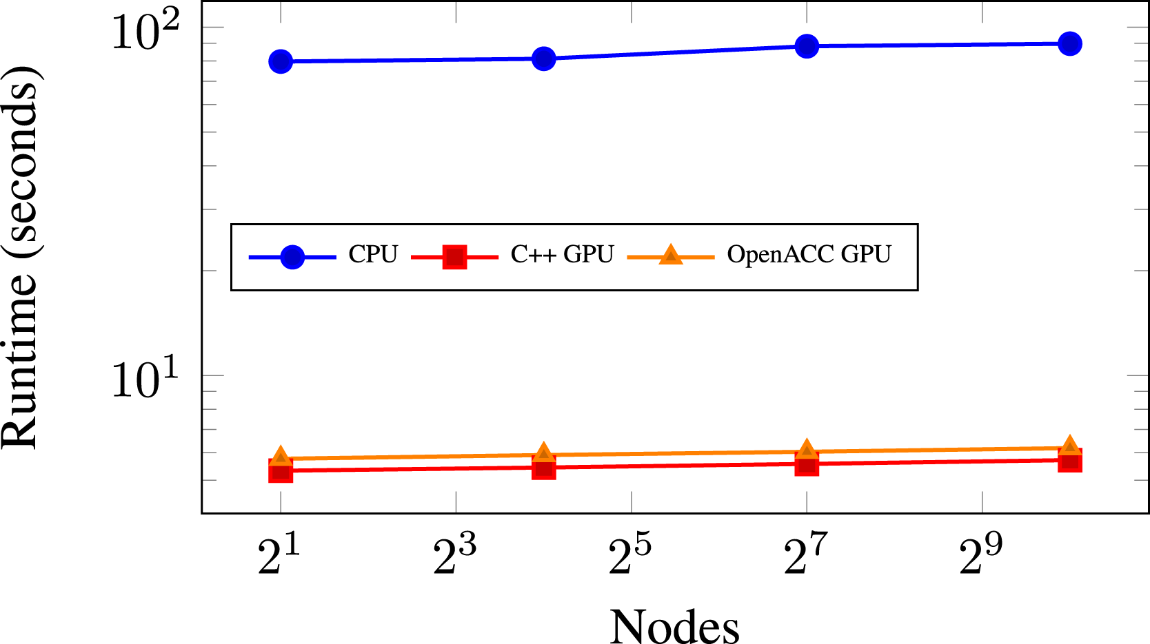
3.3. AMReX C++ programming model for PeleC on CPUs and GPUs
AMReX’s C++ programming model for CPUs and GPUs is quite similar to the Kokkos (Edwards et al., 2014), RAJA (Beckingsale et al., 2019), and GridTools (ETH Zurich, 2022) approaches for performance portability. It exploits the use of lambda functions in which the developer writes the kernels that perform calculations on a FAB. These lambda functions are then compiled into assembly code for the particular device back end requested at compile time, targeting either the CPU or a particular GPU architecture, typically using the device’s native vendor supplied programming model. AMReX’s programming model is not as general as Kokkos or RAJA, however. State variables are registered with AMReX, and AMReX performs allocation for these major data structures automatically through a memory pool allocator that can leverage a “managed” memory model supplied by the device vendor, for example, unified virtual memory (UVM) from NVIDIA. Therefore, the equivalent of a “view,” which exists in Kokkos and RAJA, and are managed by the developer, is not necessary in AMReX. Parallel loops, denoted by ParallelFor, are generally of a single variant operating over all FAB cells. This programming model simplifies development and has allowed AMReX to quickly produce back ends for NVIDIA GPUs using CUDA, AMD GPUs using HIP (Advanced Micro Devices, 2022), and Intel GPUs using DPC++ (The Khronos Group Inc, 2022).
In contrast to the OpenMP model, execution on the GPU foregoes tiling and targets one thread per cell when processing a FAB to maximize parallelism (though this pattern can inhibit vectorization). Since a single FAB might not be large enough to saturate a GPU device by itself, asynchronous behavior is necessary to calculate multiple FABs simultaneously on a single device. To obtain concurrent kernel execution on a device, “streams” are employed. Streams allow concurrency in execution for multiple kernels and guarantee that the order of execution for kernels within a stream is preserved. By AMReX placing each iteration of the A schematic on how MFIter loop iterations are executed in parallel using multiple GPU streams. This figure is reproduced from AMReX Team (2022).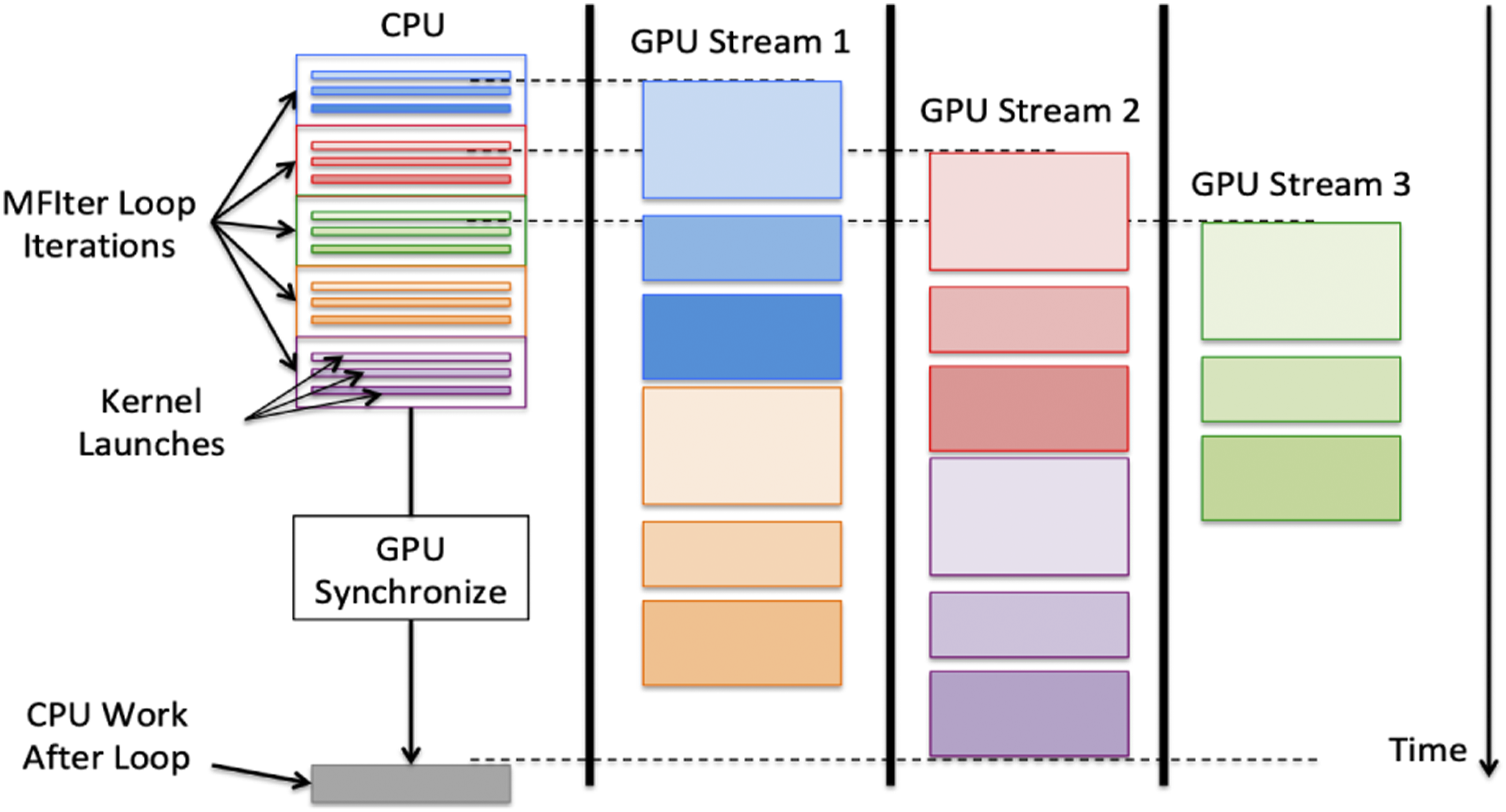
#pragma omp parallel if (amrex::Gpu::↪notInLaunchRegion()) for (amrex:: const amrex::Box& bx = mfi.tilebox(); amrex::Array4<amrex::Real> const& fab = mf.↪array(mfi); amrex::ParallelFor(bx, ncomp, [=] AMREX_GPU_DEVICE (int i, int j, int k, int ↪n) { fab(i,j,k,n) += 1.0; }); } Moving entirely to C++ has overcome many of the pitfalls experienced using mixed languages. Most notably, compilers for new computing architectures are generally not developed with Fortran support as a primary objective. Before the implementation of the AMReX C++ framework, PeleC was comprised of roughly 50k lines of code: 12k lines of C++ and 38k lines of Fortran. After conversion, PeleC became 20k lines of C++ code, achieved mainly through reducing duplicate dimensional code and removing Fortran preprocessor macros. Kernels are more compact, easier to read, and easier to debug. Compiler choice and available GPU back ends has also expanded through these efforts. After adopting the AMReX single language programming model, the only modification to PeleC necessary to support all three GPU vendors previously listed was the removal of “global managed” variables. This work has further enabled subsequent code refactors that have simplified PeleC’s organization. For example, the use of C++ templating for abstracting equation of state calls has provided a clean interface for including more complex equations of state. The code development effort for migrating to this new programming paradigm was facilitated through a straightforward mapping between Fortran loops and Fortran arrays, with the ParallelFor lambda loop statements and the Array4 C++ data structures, respectively. Approximately 140 Fortran loops were converted to the C++ lambda formulation, most of which required minimal changes between C++ and Fortran. Beyond minor language-specific local adaptations, the most common issues that arose when performing such migrations revolved around custom data structures, data locality, CPU-to-GPU synchronization, device thread synchronization, and verification of correctness. Additionally, arrays used in the ParallelFor loops were carefully analyzed to determine whether they were needed only on the device, had a fixed size, or required data to be transferred back to the CPU. This was particularly necessary for user-defined data structures involved in initial condition specifications, for example, arrays associated with time-dependent turbulent inflow boundary condition data. Particular care was paid to data locality and ensuring the required data was present where needed. Synchronization steps were also necessary, particularly for the EB sparse data structures which must be accessed simultaneously by multiple threads, requiring atomic operations in order to avoid race conditions. We found that a successful migration depends critically on the definition of a test suite that can be used to derive adequate differences between outputs of specific kernels to isolate software bugs, race conditions, and data synchronizations issues. The test suite incorporates several design goals: (i) Rapid evaluation to reduce development time; (ii) exercise the entire application to identify issues with data races, synchronization, communication patterns, and performance; and (iii) targeted testing to enable rapid detection of a problematic kernel. The test suite encompasses tests for reactions and chemistry integrators (i.e., tests with no flow physics, e.g., auto-ignition); hydrodynamic tests (pure advection, no diffusion or reactions, e.g., a canonical shock tube problem); diffusion tests (e.g., heat conduction in a fluid); and geometry tests (i.e., the previous tests with the addition of geometry, e.g., a canonical shock tube problem in a cylinder at an angle with respect to the grid). Varying the dimensionality of the test case, that is, two dimensions versus three, enabled the identification of dimension-specific issues (e.g., narrowing searches for code bugs in dimension specific code) or increased speed in the test evaluation procedure (e.g., running cases in two dimensions is significantly faster than in three dimensions). Tests with symmetrical features, for example, heat conduction around a sphere, were particularly important to identify dimension-specific issues such as misplaced indices and increments. It is also particularly important to run a subset of these tests at scale to identify issues in tiling or data races arising from specific dispositions of grid decomposition across ranks and threads. Ensuring correctness when comparing simulations on different architectures was particularly challenging, especially since GPU simulations exhibit non-deterministic differences in results due to order-of-operations randomness. Straightforward comparisons of simulation outputs, for example, pressure and velocity fields, while useful, are not sufficient to ensure correctness because of differences arising from non-identical hardware and compilers. The value of a verification test suite based on physical problems and the method of manufactured solutions was of paramount importance as it enabled physical quantities of interests, for example, shock location, diffusive transport, auto-ignition, or order-of-accuracy studies, to be compared to reference values on any given hardware. Compiler-based flags for warning checks and linting tools for static analysis such as cppcheck (Marjamaki, 2022) and clang-tidy (The Clang Team, 2022) helped identify erroneous programming, duplicate variables, code simplifications, and performance improvements. The majority of the tests used for the successful code migration of PeleC were made part of our regression test suite, which is evaluated on several different machines and a variety of compilers on a nightly basis. In the next section, we discuss how implementation of the C++ framework has allowed PeleC to perform and scale on current pre-exascale systems.
4. Performance on pre-exascale systems
This section is organized as follows: We present the machines used for benchmarking PeleC in 4.1, benchmark cases in 4.2, single node performance metrics in 4.3, and finally strong and weak scaling analysis in 4.4.
4.1. Description of HPC systems used for performance analysis
4.1.1. Summit, Oak Ridge National Laboratory (ORNL)
Summit (Oak Ridge Leadership Computing Facility, 2022), which follows the GPU paradigm, consists of 4608 nodes each containing two IBM Power9 processors with 22 CPU cores, and 512 GiB of RAM per node. Each node houses six NVIDIA Tesla V100 GPUs connected with NVLINK. Nodes are interconnected with a Non-blocking Fat Tree topology utilizing dual-rail EDR InfiniBand, providing node injection bandwidth of 23 GB/s. Each node on Summit provides a theoretical limit of 42 teraflops, for a total of roughly 200 petaflops of computational power. The approximate power utilization of Summit is 10,000 kW, leading to a power efficiency of approximately 14.7 GFlops/Watt (using the Linpack performance rating of 148 petaflops) (TOP500, 2022b.)
4.2.1. Eagle, National Renewable Energy Laboratory (NREL)
Eagle (National Renewable Energy Laboratory, 2022) is a cluster comprised of 2186 compute nodes with a theoretical peak performance of 8 petaflops. Eagle has a total of 76,104 Intel Xeon-Gold Skylake-6154 processor cores (36 cores per compute node). Each node provides a theoretical limit of three teraflops. The nodes that comprise Eagle are connected using a 100 Gb/sec EDR InfiniBand network. All nodes and storage are connected using an enhanced 8-dimensional hypercube topology that provides a bisection bandwidth of 26.4 TB/s. The approximate power utilization of Eagle is 1000 kW, leading to a power efficiency of approximately 4.7 GFlops/Watt (based on Linpack performance rating of 4.8 petaflops). (TOP500, 2022a) This is approximately 3× lower than Summit’s power efficiency.
4.1.3. Theta, Argonne National Laboratory (ANL)
Theta (Argonne Leadership Computing Facility, 2022) is a Cray XC40, 11.7 petaflops system based on the second-generation Intel Xeon Phi processor. It has 4392 compute nodes with 64 core Intel Knights Landing 7230, 16 GiB of MCDRAM, and 192 GiB of DDR4. Each node provides a theoretical limit of three teraflops. Nodes are connected via the high-speed Cray Aries network utilizing a 3-level Dragonfly topology. Recent power utilization numbers for Theta were not found. However, in 2017, the approximate power utilization of Theta was 1000 kW, leading to a power efficiency of approximately 5.8 GFlops/Watt (based on Linpack performance rating of 5.8 petaflops). (TOP500, 2022c) This is approximately 2.5× lower than Summit’s power efficiency.
Also in regard to machines used in this work, AMReX contains a database of compiler optimizations organized by compiler and specialized further by “site” or machine. The default optimizations provided within the AMReX build system were used to compile/link all tests performed here. For the major Intel compiler flags, we use -O2 with inter-procedural optimization (-ip) enabled. For the Eagle machine, specific optimization for AVX-512 vectorization (-xSKYLAKE-AVX512) is also enabled. The corresponding flag for Xeon Phi processors (-xMIC-AVX512) was activated through the compilers provided in the craype-mic-knl module on Theta. For the nvcc compiler on Summit, we use GNU Compiler Collection (GCC) as the host compiler with -O3 and the specific compute architecture for the Summit V100s enabled (sm_70) in nvcc with fast math operations enabled and register counts set to 255.
4.2. Description of performance test cases
4.2.1. Pre-mixed flame (PMF)
As shown in Figure 5, the case is defined on a rectangular domain. It is initialized with a thin methane–air flame structure. A mean flow is imposed along the positive z direction. The species and temperature profiles are taken from a pre-computed solution that represents a freely propagating one-dimensional flame featuring an inlet velocity that is adjusted so that the profiles remain steady over time. In this setup however, the velocity field in the flame region is modified by adding small periodic perturbations that result in the development of corrugations on the flame surface. We use the DRM19 chemistry (21 species, 84 reactions) (Bell et al., 2007), coupled with an ideal gas model, a configuration typically used in PeleC’s regression tests. Throughout this article, the number of cells is the metric used to describe the size of the problem. The number of DoF is achieved by multiplying the number of cells by 26, corresponding to the number of state components in each cell: density, 3 momentum components, energy, and 21 species. Volume rendering of vorticity magnitude and contour of 1250K temperature (orange) for the PMF case showing the perturbations added to the flow field to introduce flame surface corrugations.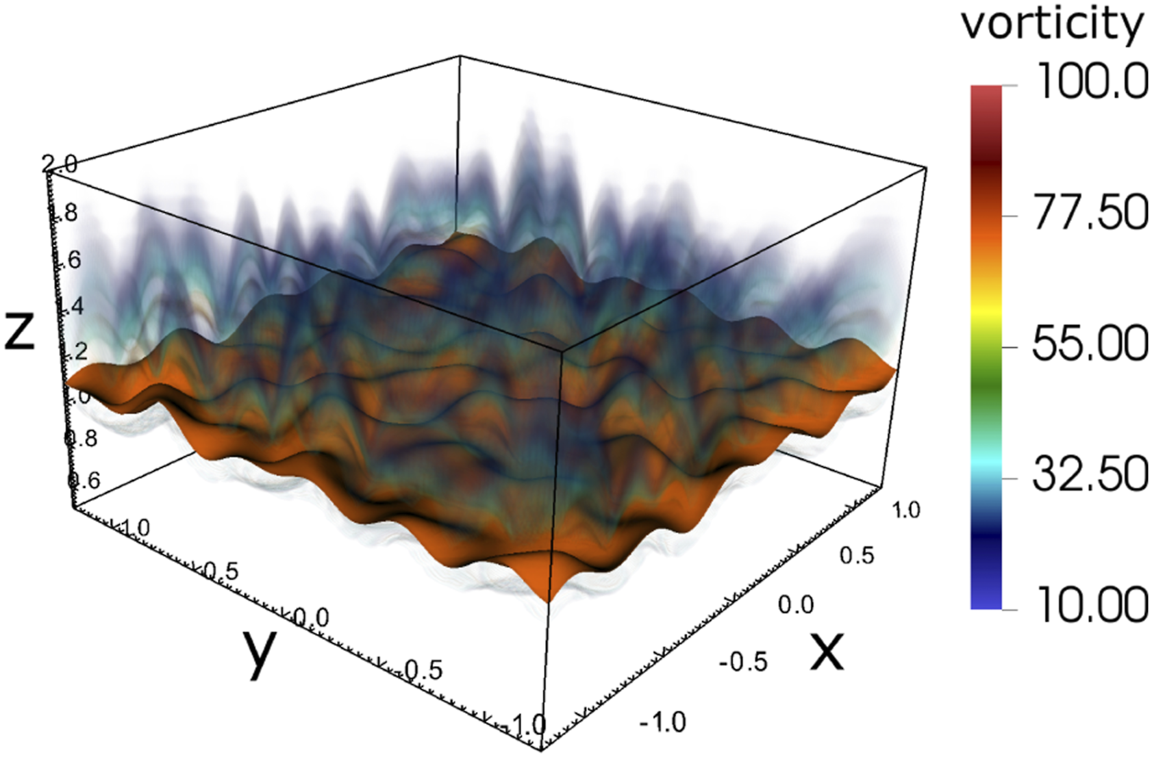
4.2.2. Piston bowl
Production and research engines use pistons with varying geometry, ranging from flat to complex re-entrant bowls that concentrate and enhance the flow structures. We used a piston bowl configuration resembling a production turbocharged diesel engine for this study; a schematic can be seen in Figure 6. In compression ignition engines, fuel is typically added toward the end of the compression stroke through a multi-hole injector, with the details of the injector design specific to the fuels and operating mode under study. For our case, we inject gas-phase fuel (methane) through seven discrete jets into high temperature air as a generic configuration. The DRM19 chemistry is also used for this case. A rendering of the jets spreading in the domain from a high resolution simulation of the piston bowl after several thousand time steps is also shown in Figure 6. For the purposes of performance measurements, these tests were devised to be close to real-world simulation configurations with appropriate surface to volume ratios, cell counts, and chemistry complexity. The PMF case has an unbalanced load in space due to reactions in the flame sheet and does not exercise complex geometry. The piston bowl case has a realistic geometry and exercises the EB algorithms and reactions in the jets. Schematic of the piston bowl simulation configuration and simulation snapshot.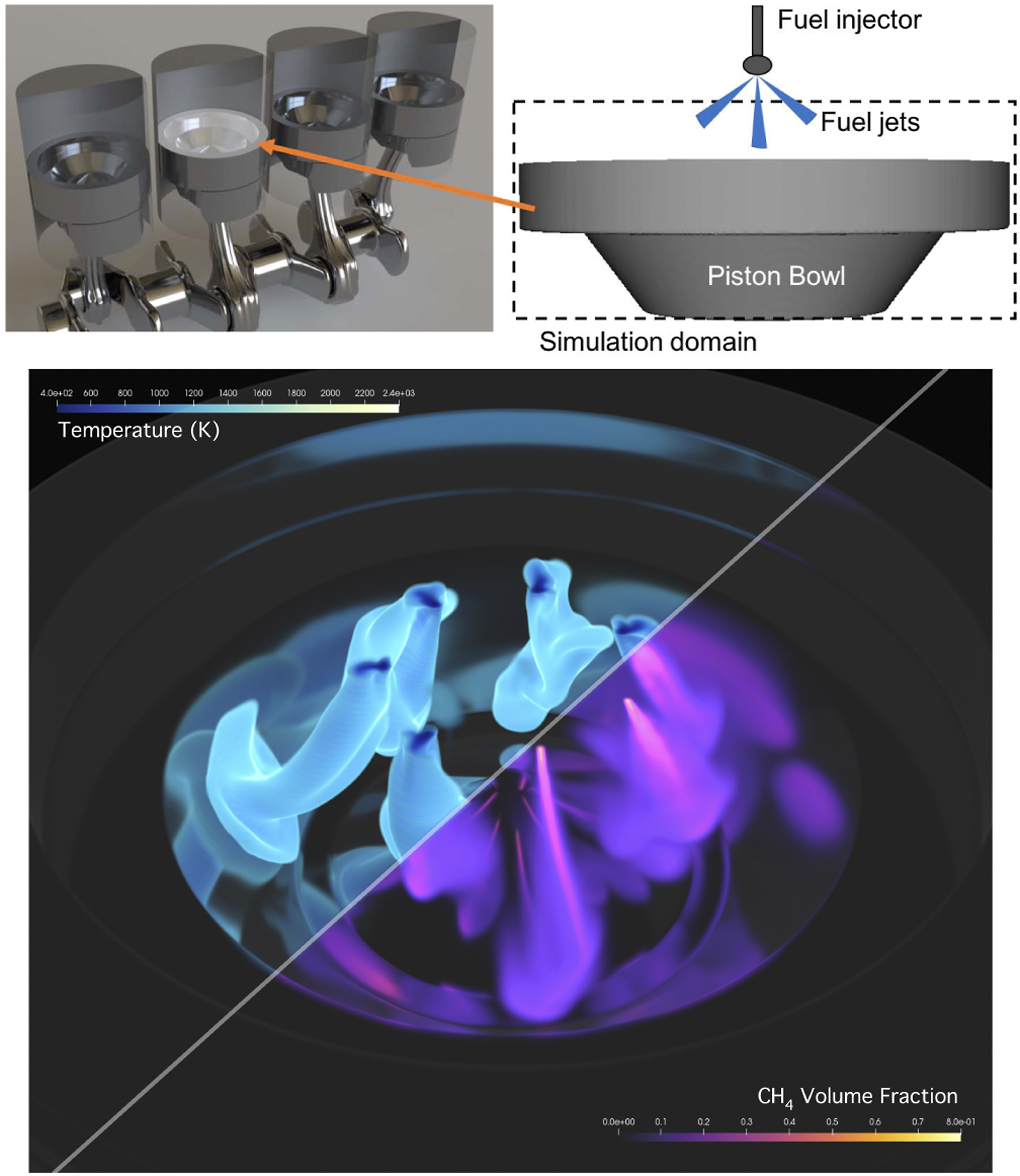
4.3. On-node profiling analysis
In this section, we run and profile the performance test cases on a single node on Eagle. We begin by profiling on a single node to ignore factors in performance that are dominant using the distributed MPI model and to focus on measuring runtimes for core PeleC routines.
For this analysis, the PMF problem was run using 963 cells (23 million DoF) and the piston bowl case was run with 64 × 64 × 24 cells (2.5 million DoF) with one level of AMR. Both of these cases use the DRM19 reaction mechanism and the RK64 integrator for chemistry integration. The simulations were profiled using AMReX’s built-in tools (Gott 2022). We do not provide the profile tables in order to maintain brevity.
In both cases, computing the source term from the chemical reactions is the most time-consuming operation, 87.4% of the runtime for the PMF and 94.40% for the piston bowl. The computation of the hydrodynamic and diffusion fluxes never exceeds 6% of the runtime. EB-specific routines for the piston bowl are negligible, remaining below 2% of the runtime. By ignoring large-scale MPI bottlenecks, we observe that most of PeleC’s runtime is in the chemistry routines, and even with EB in a significant area of the domain, we find the EB routines to be mostly insignificant during runtime.
4.3.1. Chemical reaction routine and the chemical mechanism size
The fuel type and chemical mechanism play an important role in a combustion simulation and the chemistry calculation with the RK64 integrator is the most time-consuming routine. Therefore, we analyze how the complexity of the chemical mechanism affects PeleC’s runtime. These tests used the RK64 integrator and an ideal equation of state.
In Figure 7, we compare a single node piston bowl simulation on Summit, Eagle, and Theta.
1
We observe a speedup of approximately 10× from a Theta node to a Summit node across a range of chemical mechanism sizes (horizontal purple line). Based on approximate power utilization, Section 4.1, this translates to a 1.25× power reduction on Summit. Figure 7 shows that the number of species in a mechanism has a linear effect on runtime. In Figure 7, the solid green line is our observed increase in runtime, and the dashed green line is the linear extrapolation based on number of species. These results indicate that a priori runtime estimates can be obtained for other mechanisms by scaling for the number of species, though this estimate is subject to the relative stiffness of the different mechanisms. Performance comparison of different chemistry mechanisms on a single node of Summit, Eagle, and Theta for the piston bowl case with 0.6M cells (15.6 million DoF), and one level of AMR.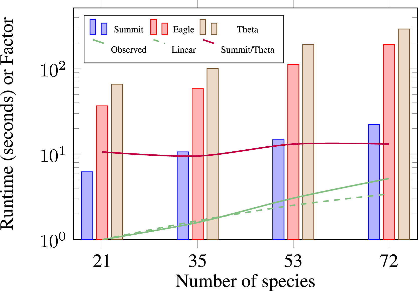
By understanding the performance implications of chemistry, it is clear that the ODE integrator solving these equations is paramount to reducing the time per time step in PeleC. Therefore, SUNDIALS (Hindmarsh et al., 2005), a well-established library of ODE integrators, was interfaced into PeleC as an optimization. Replacing the built-in RK64 integrator with SUNDIALS for our test cases led to a speedup of 6× as shown in Figure 11.
To understand GPU utilization after this optimization, we performed a roofline analysis of the top three time-consuming CUDA GPU kernels in the application using Nvidia’s Nsight Compute tool, shown in Figure 8. The most expensive kernels are fKernelSpec (54% of the total runtime), which is responsible for computing the right hand side of the reaction ODEs, and linearSumKernel (10% of the total runtime) and scaleKernel (7% of the total runtime) are part of SUNDIALS which perform vector operations. These three kernels are major parts of chemistry integration computation. A V100 GPU has a theoretical maximum double precision performance of 7 TFLOP/s and 900 GB/s memory bandwidth. The most time-consuming kernel, fKernelSpec is achieving an arithmetic intensity of 1.63 and memory rate of 625 GFLOP/s, which equates to 9% of peak performance. The linearSumKernel and scaleKernel achieve an arithmetic intensity of 0.13 and 0.07, respectively. They also achieve a rate of 106 GFLOP/s and 50 GFLOP/s, respectively. Though these two kernels are in SUNDIALS, the Pele developers collaborate with the SUNDIALS developers with further improvements expected in the future. Roofline analysis of the top three time-consuming GPU kernels on a single V100 for the piston bowl case with DRM19 chemistry.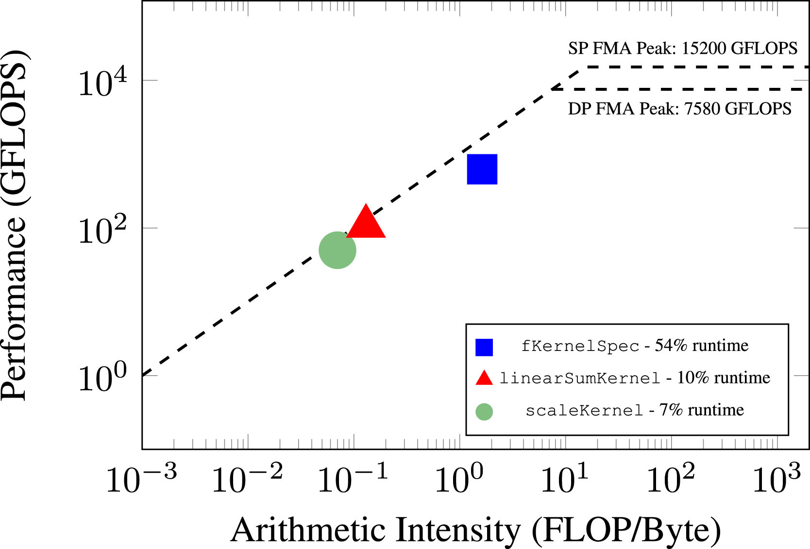
We also include a roofline analysis using an Intel Skylake CPU on Eagle, shown in Figure 9. The top three time-consuming routines are shown from data collected using Intel Advisor. The most time-consuming routine, dvode, is responsible for computing the right hand side of the reaction ODEs and accounts for 32% of the runtime. This routine achieves an arithmetic intensity of 0.038 and a memory rate of 12 GFLOP/s. The other two routines, dvjac (Jacobian of the ODE system) is responsible for 8% of the total application runtime, while umeth3d (hydrodynamics) is responsible for 8% of the total application runtime as well. The dvjac and umeth3d routine achieve an arithmetic intensity of 0.083 and 0.071, respectively. They also achieve a rate of 4.49 GFLOP/s and 11.02 GFLOP/s, respectively. This indicates the original CPU baseline does not suffer from obvious inefficiencies. Roofline analysis of the top three time-consuming CPU routines on a single Intel Xeon-Gold Skylake core for the piston bowl case with DRM19 chemistry, using the Intel 2018 compiler for the F90 and DVODE code pathway.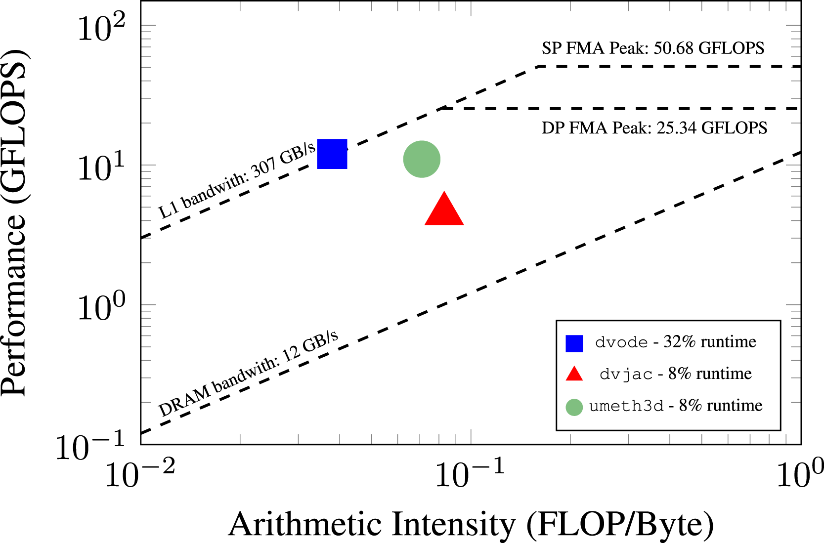
4.4. Scaling results
In this section, we perform strong and weak scaling studies of PeleC for GPUs on Summit and CPUs on Eagle in order to observe PeleC’s performance in its intended setting for large-scale simulations. For brevity, scaling results on Intel Xeon Phi machines are not discussed here. Scaling studies using a legacy version of the PMF case were performed in 2018 on the NERSC Cori machine and showed excellent weak scaling to 4096 nodes, using four threads per rank on the Xeon Phi hardware. This corresponded to approximately 525k concurrent threads. Over this range of scaling, we observed a 12% drop in parallel efficiency compared to a single node. In the following section, we focus instead on scaling and performance of PeleC on emerging GPU-based architectures.
4.4.1. Strong scaling results
We run three scaling cases: (i) Strong scaling the PMF problem on Eagle and Summit using the RK64 chemistry integrator, (ii) strong scaling the PMF problem on Eagle and Summit using all available chemistry integrators, and (iii) strong scaling the PMF problem using 4096 Summit nodes while performing reductions in the number of cells. In the third study, we use the SUNDIALS for chemistry integration. We omit a strong scaling study of the piston bowl as the results are similar to the PMF case with negligible costs associated with EB.
First, we compare the performance and scaling of the PMF problem using a 3843 coarse grid with two levels of AMR, for a total of around 360 million cells or 9.4 billion DoF. This case was run on the Eagle machine at NREL and the Summit machine at ORNL to compare and understand the initial capabilities of our full GPU port. We use PeleC’s built-in RK64 integrator for chemistry so that we are only comparing changes in the programming model and hardware in which it is running, essentially using the same code path on each device.
Figure 10 shows the results from this study. From these results, we first notice that the CPU runs have deficiencies around one million cells per node on both Summit and Eagle. Note that this effect is not present on the GPU. Second, we observed that the C++ kernels are around 2× faster than the Fortran kernels with GCC on Summit. Although the Fortran case is not tested with other compilers in this plot, nor was it investigated further, we have found the C++ kernels to be 2× faster than the Fortran kernels in general on the CPU, as is also the case on Eagle in Figure 11. We hypothesize that this speedup is due to removing the multiple language barrier which simplified compiler optimizations. Function calls are also forcibly inlined in the kernels for reduced register usage on the GPU. However, further investigation into this phenomenon was not performed as the focus of this work was the switch to the C++ ParallelFor framework for GPU performance. Third, we note the performance speedup of the application running on the Summit GPUs. Using the 128 node runs as an example, the GPU performance node-for-node is approximately 14× faster than the Eagle Skylake nodes using the Intel compiler, 56× faster than running with GCC on the Summit CPUs, and 125× faster than running on the Summit CPUs using GCC with the original Fortran kernels. We note that a Summit node is 14× faster in C++ than an Eagle and Theta node in terms of theoretical FLOP/s. Therefore, the observed 14× speedup for the same code pathway between Summit and Eagle can be expected. A Summit node is comprised of two IBM Power9 processors, each one achieving 0.56 teraflops (Sorokin et al., 2020), leading to a 42× speedup from using the CPUs to using the GPUs. The additional speedup observed in the GPU run is most likely due to using GCC for the IBM Power9 CPU run which may not be the optimal choice. Strong scaling of PMF case with DRM19 chemistry and built-in RK64 integrator for chemistry on the Summit and Eagle machines. 360M cells (9.3 billion DoF) with 2 levels of AMR. Using the Intel 2018.4 compiler on Eagle. Strong scaling of PMF case with DRM19 chemistry on the Summit and Eagle machines. 164M cells (4.2 billion DoF) with 2 levels of AMR. Using the Intel 2018.4 compiler on Eagle.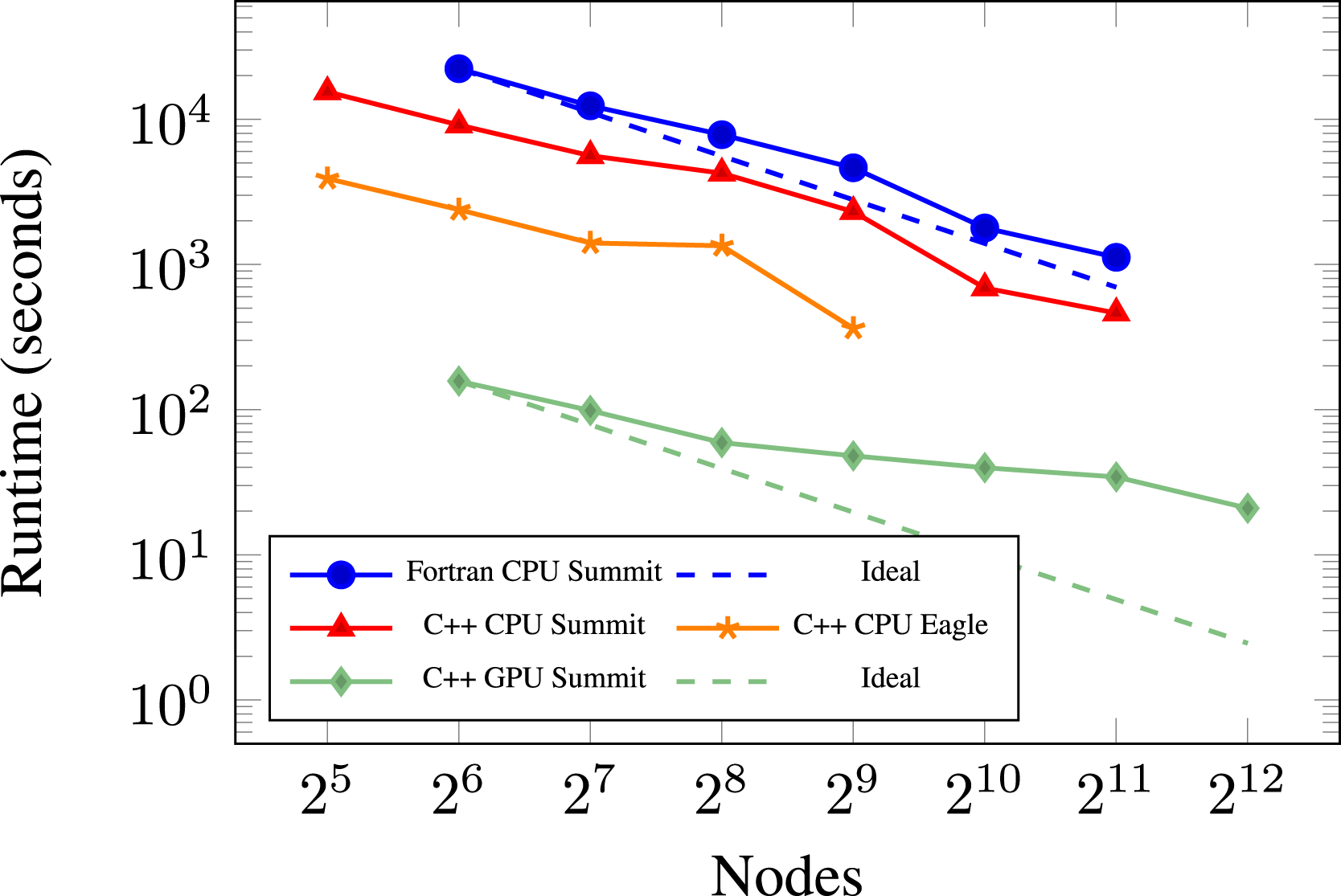
We see that as strong scaling continues on the CPUs, the GPUs exhibit less ability to strong scale mostly due to the increase in weight of data transfers between CPU and GPU for communication of halo-exchanges (ghost cell data) across MPI ranks. 2
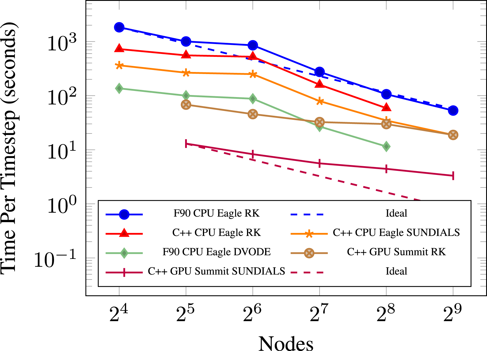
Next, we compare the performance and scaling of the PMF problem using a 2563 coarse grid with two levels of AMR. We use this experiment to compare the different chemistry integrators available. Performing strong scaling gives us a better overview of the performance of PeleC, as well as illustrating the performance of each ODE integrator. Different locations on the plot can experience varying amounts of speedup, so testing more cases gives us a more general survey of performance gains. The plot for this experiment is in Figure 11. Again, we use the Intel compiler on Eagle which we know to be the best compiler choice when running on its Skylake processors.
Reviewing our results for this experiment, we again notice a performance deficiency on the CPU, now at 2.5 million cells per node. A speedup of 2× is again observed between Fortran and C++ with the explicit RK64 chemistry integrator. The C++ case with SUNDIALS achieves a 2× speedup over the explicit RK64 integrator on the CPU. The last CPU case is our original programming model with Fortran and DVODE, which we see to be the highest performing configuration for the CPU. This case actually performs similarly to our GPU version of the code on Summit using the explicit RK64 integrator and begins to perform even better at smaller cell counts per node. These two cases are arguably the truest comparisons between our initial GPU port and the previous Fortran kernels, where we compare the highest performing CPU configuration known against our highest performing GPU configuration known, allowing for using the machine best suited for each numerical scheme. We find that our Fortran version of PeleC using DVODE seems quite competitive with our initial GPU port, which is what one might expect during a first pass at porting an application to the GPU. However, with the interface to SUNDIALS on the GPU, the GPU implementation on Summit is notably faster (about 6× in this case) than the fastest configuration we have on the CPU, that is, Fortran with DVODE on Skylake with the Intel compiler. The 14× speedup between a Summit and Eagle node is again observed in the C++ comparison where SUNDIALS is used for both. For each case both on the CPU and GPU, we see strong scaling continue to provide speedup when given more resources even at 9k cells (234k DoF) per core on the CPU and 53k cells (1.3 million DoF) per GPU. Again, we find the GPU speedup to fall off at a faster rate than the CPU cases with fewer cells. Running on a large amount of CPUs on Eagle, for example, can provide a smaller time per time step than running on the GPUs on Summit at an equivalent node count. The plot also shows that the same simulation running on 256 Eagle nodes achieves roughly an equivalent time per time step as running on 32 Summit nodes. 3 This offers at least an 8× reduction in node count required for such simulations from Eagle to Summit, which translates to a 1.8× reduction in power utilization.
Lastly, we show a static scaling plot (Chang et al., 2018a,b) for 4096 Summit nodes in Figure 12 where the number of cells in the problem is reduced as opposed to increasing the number of nodes. SUNDIALS is used as the chemistry integrator and two levels of AMR. Results are shown in this manner mainly to illustrate PeleC’s ability to utilize 90% of the Summit machine to run an extremely large 160 billion cell problem with 6.5 million cells (169 million DoF) per GPU (which is the limit for the Summit V100 GPU memory for the PMF DRM19 case), while also scaling down to an 11 million cell problem using 3k cells per GPU. We see PeleC continue to provide speed gains over a very large span of problem sizes. When profiling the small cell count cases, we find that runtime is dominated by the halo-exchange communication in MPI. The halo-exchange scales poorly while computing the right hand side of the reaction ODEs, fKernelSpec, scales down to 104 cells per GPU. The fall-off in scaling beyond this may be due to kernel launch latency and requires further investigation. Static scaling (Chang et al., 2018b,a) of PMF case with DRM19 chemistry on 4096 Summit nodes. Varying number of cells with 2 levels of AMR.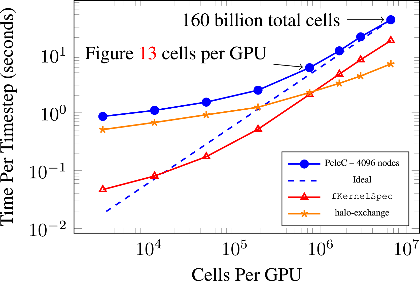
4.4.2. Weak scaling results
To understand PeleC’s ability to scale the problem size along with computational resources, we perform a weak scaling study. The PMF case is again used with SUNDIALS, with two levels of AMR. The problem domain size is scaled in both the x and y dimensions, leaving the z dimension fixed, and keeping the fraction of cells in the reacting zone constant. Around 750k cells per Summit, GPU is used, which provides a time per time step of less than 10 s on a single node. The number of cells in this problem is scaled along with the number of nodes, moving from one node to all 4608 nodes available on Summit. The number of cells involved is approximately 20 billion in the 4608 node case. Results for this weak scaling experiment are shown in Figure 13. Weak scaling of PMF case with DRM19 chemistry. Approximately 750k cells (19.5 million DoF) per GPU with 2 levels of AMR. The baseline is the average time per time step for the single node case.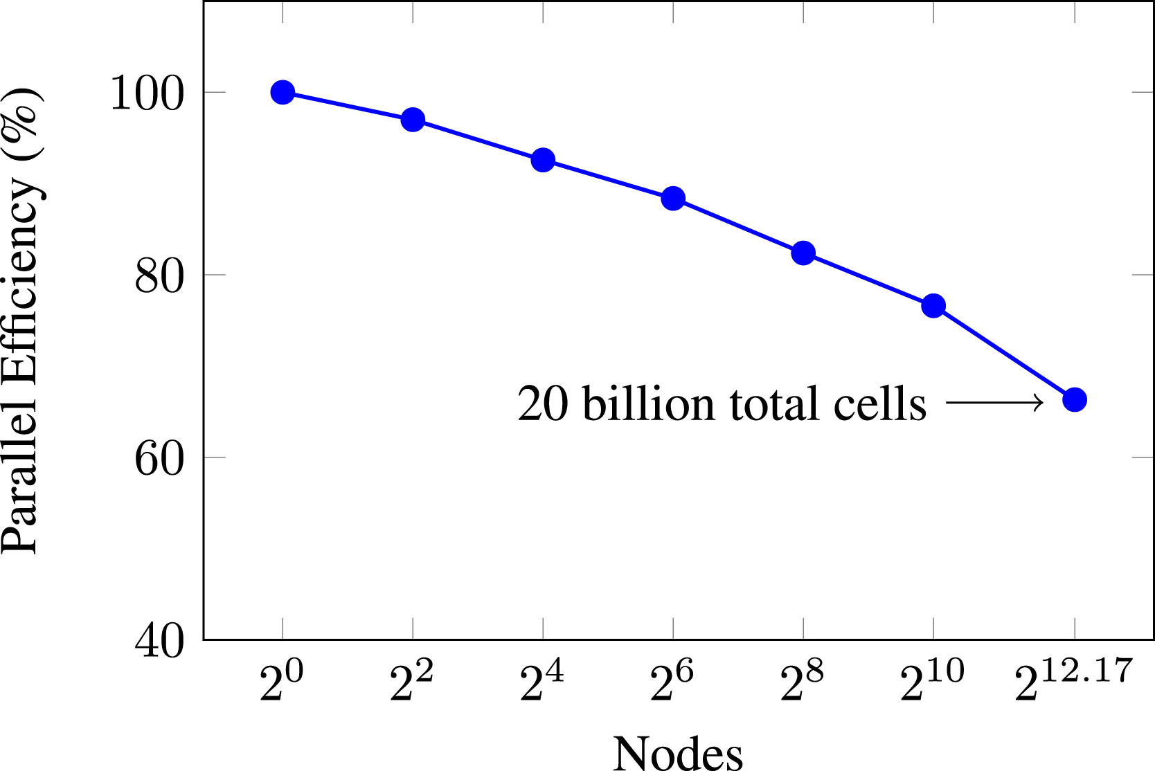
As expected, parallel efficiency is lost when moving from a single node to multiple nodes. However, this loss is very respectable at approximately 34% when transitioning from a single Summit node to every node on the machine. In this sense, we see that PeleC is very capable of running massive simulations efficiently utilizing 100% of the world’s second most capable supercomputer (according to the top500.org list at the time of writing (TOP500, 2020)). Again, when observing the profile breakdown for PeleC on the largest simulations, we find that runtime is dominated by the halo-exchange communication in MPI which also requires the extra step of data transfer between the CPU and GPU.
4.5. Performance summary
There are numerous ways to attempt a comparison of performance and tuning activities for a given HPC application. We ran three strong scaling studies and a weak scaling study in order to get a general overview of performance for our most significant development work in PeleC. These have been porting kernels from Fortran to AMReX’s C++ framework to enable PeleC on the GPU and implementing an interface to ODE integrators in the SUNDIALS library as our ODE solver of choice on the GPU. After developing these capabilities, we find that, at the time of this writing, running on Summit’s V100 GPUs is faster and more power efficient to obtain simulation results using PeleC than using a CPU-based machine such as Eagle. The power efficiency gains are approximately a factor of two between Summit and Eagle. It is also clear that, in the strong scaling limit, CPU-based machines such as Eagle may lead to faster solution times. However, the machines used in this study do not have enough CPUs to be able to demonstrate this hypothesis. We are also able to run problems at resolutions well in excess of what is typical for today’s combustion research codes, enabling new science cases for combustion researchers.
Our approach to implementing EB has shown to be fairly insignificant in computation time for our test problems. We know that calculating the reaction source term requires the greatest amount of runtime in PeleC itself. Therefore, implementing the third party library, SUNDIALS, has given speedups of around 6× over the built-in RK64 integrator for calculating reactions. Other than the chemistry integration algorithms, there does not seem to be a significant platform dependence on the algorithms chosen for transport (hyperbolic and diffusion operator treatment). Explicit chemistry integration within SUNDIALS was observed to be the faster option on the GPU in some reacting cases compared to implicit methods that require matrix solves, which tend to be faster on the CPU.
5. Conclusions and outlook
In this article, we provided a summary of PeleC’s capabilities and the chronology of programming models that were implemented for execution on shifting HPC architecture targets. Though an effort was made to preserve the original Fortran code and enable execution on the GPU, it was ultimately abandoned. In doing this, we have shown that using a pragma-based model like OpenACC allows for similar GPU performance to modern C++ lambda-style abstractions. After prototyping PeleC in C++, it became obvious that maintaining a mixed C++/Fortran code base was not desirable. PeleC has benefited from AMReX’s latest programming framework and the SUNDIALS library, including (i) a significant reduction in the number of lines of code, (ii) a simpler programming model which is performance portable across multiple architectures, and (iii) demonstration of massive simulations on 90%–100% of Summit. We demonstrated the efficacy of this programming framework through simulations that experienced speedups on one of the largest supercomputers currently available.
There are a number of opportunities to further enhance the performance of PeleC on modern computing hardware, including, but not limited to, adaptable choice of chemistry integration method (explicit vs. implicit) with varying coupled time step sizes and AMR levels, ODE solvers tuned directly to each vendor’s hardware, low-level optimization techniques which have not yet been exposed to the user through AMReX such as shared memory on device, optimizing data transfers and data locality, more informed load balancing techniques, and equation of state routine optimizations in the chemistry evaluations.
While porting from Fortran to AMReX’s C++ framework has provided PeleC with clear performance improvements, it was also done with the goal of allowing PeleC to run on the first US exascale machines: Aurora and Frontier. Aurora is a machine due to arrive at ANL in 2022 with a GPU architecture from Intel, with the primary programming model to be DPC++. Frontier is a machine due to arrive at ORNL in 2022 with a GPU architecture from AMD, with the primary programming model to be HIP. AMReX’s C++ framework is able to support all of these programming models. PeleC has been tested successfully with the latest Intel OneAPI DPC++ compilers (The Khronos Group Inc, 2022), as well as AMD’s latest HIP compilers at the time of writing on pre-production hardware for each machine. Given these results on pre-production exascale hardware and PeleC's ability to run a 160 billion element simulation on 90% of Summit and to weak scale at a reasonable time per timestep up to 20 billion elements on all of Summit, it is clear that PeleC will be able to use exascale supercomputers immediately and effectively to expand combustion science capability far beyond our current limits.
Footnotes
Declaration of Conflicting Interests
The author(s) declared no potential conflicts of interest with respect to the research, authorship, and/or publication of this article.
Funding
The author(s) disclosed receipt of the following financial support for the research, authorship, and/or publication of this article: This work was authored in part by the National Renewable Energy Laboratory, operated by Alliance for Sustainable Energy, LLC, for the U.S. Department of Energy (DOE) under Contract No. DE-AC36-08GO28308. Funding was provided by U.S. Department of Energy Office of Science and National Nuclear Security Administration. The views expressed in the article do not necessarily represent the views of the DOE or the U.S. Government. The U.S. Government retains and the publisher, by accepting the article for publication, acknowledges that the U.S. Government retains a nonexclusive, paid-up, irrevocable, worldwide license to publish or reproduce the published form of this work, or allow others to do so, for U.S. Government purposes. This research was supported by the Exascale Computing Project (17-SC-20-SC), a collaborative effort of the U.S. Department of Energy Office of Science and the National Nuclear Security Administration. A portion of the research was performed using computational resources sponsored by the Department of Energy’s Office of Energy Efficiency and Renewable Energy and located at the National Renewable Energy Laboratory. This research used resources of the Oak Ridge Leadership Computing Facility, which is a DOE Office of Science User Facility supported under Contract DE-AC05-00OR22725.
Notes
Author biographies
Dr. Marc T. Henry de Frahan is a computational scientist at the National Renewable Energy Laboratory. He develops high-fidelity turbulence models to enhance simulation accuracy and efficient numerical algorithms for high-performance computing hardware architectures. In addition to traditional physics-based modeling, he integrates deep neural networks into modeling and reinforcement learning into advanced control strategies.
Dr. Jon S. Rood is a computational scientist at the National Renewable Energy Laboratory. He currently works on performance engineering of next-generation applications for both wind energy and combustion energy under the U.S. Department of Energy’s Exascale Computing project. He has also previously worked on high-performance computing projects for agent-based simulations of ancient societies at Argonne National Laboratory, instrument analysis applications for NASA while at Tech-X Corporation, bioinformatics applications while at Lawrence Berkeley National Laboratory, and weather and climate applications while at ETH Zürich.
Marc S. Day manages the High-Performance Algorithms and Complex Fluids Group within the Computational Science Center at the National Renewable Energy Laboratory. He dedicates his time to developing algorithms for large-scale scientific computations of complex fluid flow problems. Over his career, Marc has contributed to projects associated with compressible and low Mach number astrophysics, compressible and low Mach number terrestrial combustion, and reacting multiphase flows in subsurface porous media.
Dr. Hariswaran Sitaraman is a research scientist in the Computational Science Center at the National Renewable Energy Laboratory. His expertise is in the computational modeling of reacting flows and in the development of associated numerical methods on current and upcoming high-performance computing architectures.
Dr. Shashank Yellapantula is a staff scientist in the High Performance Algorithms and Complex Fluids Group in the Computational Science Center where he leads development of exascale application software in wind energy and combustion. He is also actively involved in using Machine Learning techniques to improve and augment simulation based models for industrially relevant flow physics problems.
Dr. Bruce A. Perry joined the High-Performance Algorithms and Complex Fluids Group within the Computational Science Center at the National Renewable Energy Laboratory after completing his doctoral research at Princeton University, where his research focused on development of physics-based models for large eddy simulation of turbulent combustion systems. At the National Renewable Energy Laboratory, Bruce has expanded his work on turbulence and combustion model development to include the use of machine learning to augment or replace physics-based models in regimes where the established models do not perform well.
Dr. Ray W. Grout is the director of the National Renewable Energy Laboratory’s Computational Science Center. He also serves as a point of contact for the Advanced Scientific Computing program, where he leads that program in computing research for the U.S. Department of Energy’s (DOE’s) Office of Science.
Ann Almgren is a Senior Scientist in the Center for Computational Sciences and Engineering and the Department Head of the Applied Mathematics Department in the Applied Mathematics and Computational Research Division. Her primary research interest is in computational algorithms for solving PDEs in a variety of application areas. Her current projects include the development and implementation of new multiphysics algorithms in high-resolution adaptive mesh codes that are designed for the latest multicore architectures. She is a SIAM Fellow, the Deputy Director of the ECP AMReX Co-Design Center, and serves on the editorial boards of CAMCoS and IJHPCA.
Dr. Weiqun Zhang is member of the Center for Computational Sciences and Engineering at the Lawrence Berkeley National Laboratory. He is the chief architect of the ECP-funded AMReX software framework for supporting block-structured AMR applications. Previously he has worked on a number of other subjects, including radiation hydrodynamics, relativistic hydrodynamics/magnetohydrodynamics and gamma-ray burst afterglows.
Dr. John B. Bell is a is a Senior Scientist in the Center for Computational Sciences and Engineering. His research interests are in the development and analysis of numerical methods for partial differential equations arising in science and engineering, in addition to general topics in scientific computing, computational physics, and fluid dynamics.
Dr. Jacqueline H. Chen is Senior Scientist in the Chemistry, Combustion and Materials Science Center at Sandia National Laboratories. Her research applies massively parallel computing to the simulation of turbulent combustion.