
Abstract
The structure of the microfibrils network poses the key challenge to understand not only the mechanical behaviours but also the growth mechanisms of the plant cell wall. A number of competing hypotheses with contradictory assumptions, including the recently proposed contact model and the more conventional tethering model, have been proposed to address the challenge. In the present study, a fibre-reinforced hyperelastic model is proposed aiming to cover both the contact model and the tethering model in a unified mathematical framework. A variety of anisotropies, including those arising from the moiré pattern and the contacts, are taken into account. The formulation is presented in terms of the principal stretches for more direct correlation with the biological experimental observations. The details of the stresses and tangent moduli are provided for readily implementing in finite-element modelling. The simple shear problem is studied to provide the quantitative insight into the long-term biological hypothesis that cell wall growth is driven by shear deformations. The moiré pattern under tensile stretch is demonstrated. The local motion of microfibrils is examined by using rod theory. A corresponding potential growth mode is proposed with the analysis using Burgers vector and torsion in material space.
1. Introduction
The plant cell wall is a multilayer composite in which cellulose microfibrils (CMFs) are playing the role as the fibre reinforcement while the matrix is composed of hemicellulose, pectins, and proteins. A number of publications provided the extensive reviews about the recent progresses [1–9] and the top open questions [10] on the multiscale modelling of the cell wall and its growth from different points of view. Noticeably, both the progresses and open questions focus on the understanding of the cell wall structure, the integration mechanisms of the wall components, and the corresponding mechanical regulations of growth at nano- and larger scale.
As the major load-bearing framework, the structure of the microfibrils network poses the key challenge but also serves as the key clue in the research of the cell wall. A number of hypotheses have been proposed to address the challenge. The different hypotheses, however, may contain the very different, even contradictory, assumptions about the CMFs network.
One of the recently proposed hypotheses of interest is that, the CMFs make a load-bearing network via close physical contacts with one another in bundled regions that potentially function as sites of cell wall loosening and creep [1,2]. The contact, which may be also called a ‘hotspot’ [1], is a thin patch of xyloglucan trapped between the adjacent CMFs bundles so as to play the role of the glue to connect the adjacent CMFs bundles together [3]. This is different from the more conventional tethering model in which the mechanical connections between the CMFs were made by extended xyloglucan chains (part of hemicellulose) that adhered noncovalently to CMF surfaces [11,12].
In the tethering model, the cell wall could be modelled as a composite in which the CMFs as fibres are embedded into and connected via the matrix composed of hemicelluloses and pectins (see Figure 1(a)). Hence the growth of the cell wall was supposed to be regulated by the yielding of matrix even though the CMFs provided the key mechanical stiffness [12–14].
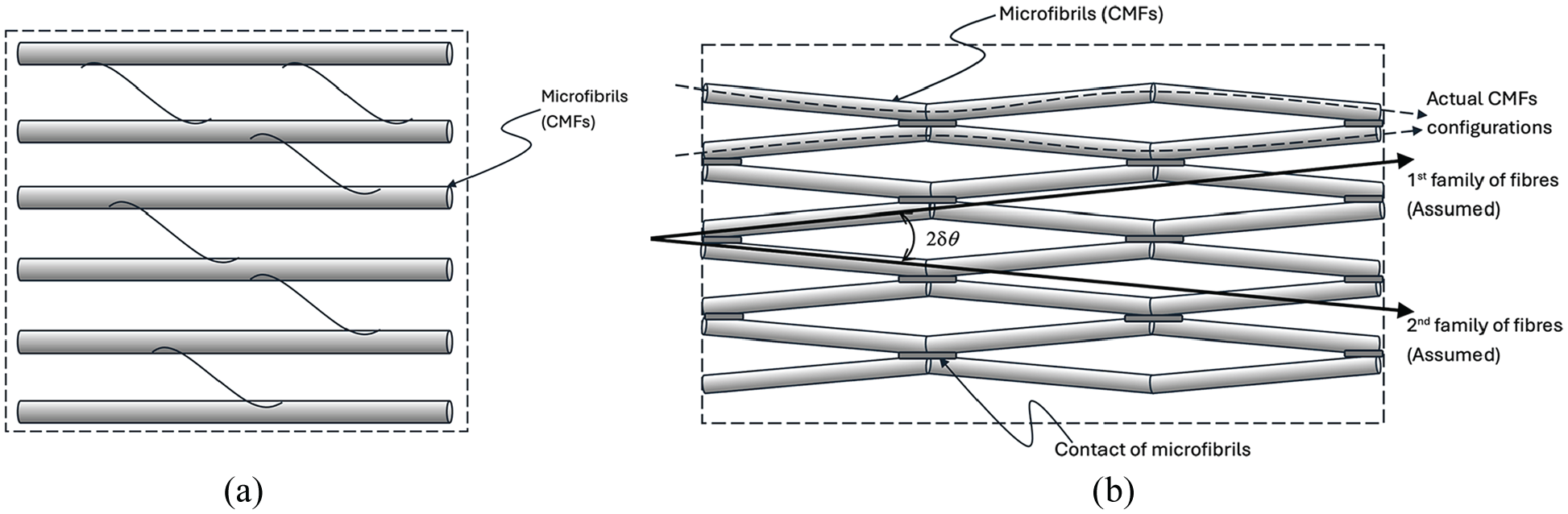
Two CMFs network models: (a) tethering model in which CMFs are imbedded into and connected by the matrix composing of hemicellulose, pectins and proteins; (b) contact model where CMFs show waviness and are connected directly by some contacts, which is proposed to be geometrically characterised by two assumed families of fibres with the waviness angle
By contrast, in the contact model, the direct contacts (connections) between the CMFs may play the key roles in the regulation of the expansive growth of the cell wall as the model suggests that the expansion of the cell wall is mainly constrained by the contacts rather than the matrix surrounding the CMFs [1]. The CMFs may be considered as a interconnected nano-fibre network on its own which, with a weak coupling with the matrix, may independently regulating both the mechanical stiffness and growth of the cell wall (see Figure 1(b)). This is different from the postulate in the tethering model that the CMFs are relative inert and playing a passive role in growth regulation [12].
From the point of view of fibre-reinforced material modelling, in the tethering model, the CMFs at a representative material point of one lamina (layer) of the cell wall may be modelled as one family of the unidirectional fibres imbedded in the matrix. By contrast, in the contact model, the direct connections between the CMFs need to be taken into account. Therefore, one of the questions of interest is if there is a unified mathematical modelling framework to cover both the tethering model and the contact model so that both models may be formulated and validated in a comparable way.
In this study, a finite strain fibre-reinforced hyperelastic model is proposed to address this question. On one hand, the proposed method may cover the tethering model straightforwardly as a material with one-family of reinforced fibres. On the other hand, to reflect the hypothesis of the contact model, rather than one-family of the actual CMFs, it is proposed that there are two assumed families of fibres in the lamina (see Figure 1(b)). The angle,
It is noted that, by comparison to the tethered model, the contact model may contain additional anisotropies besides the anisotropy due to the presence of physical fibres (CMFs) which is in the scope of the well-established theory of fibre-reinforced materials. This study postulates two classes of additional anisotropies. The first is the anisotropy of moiré pattern which is created by two neighbouring (overlapping) cell wall laminae. Moiré pattern usually is created by a small misalignment of two layers of 2D material, e.g., bilayer graphene [15–18]. In the contact model of cell wall, given that two neighbouring laminae have a finite relative rotation, the small waviness angle
Taking all the above anisotropies into account, both the tethering model and the contact model may be formulated in a unified mathematical framework. The challenge is to formulate in a way that may be directly correlated with the biological experiment observations, especially the roles of the contacts in the regulation of mechanical and growth behaviours.
Geometrically, a cell wall is a thin-walled structure. Therefore, the stretches of the wall surfaces are the prominent indications of the mechanical behaviour of the cell wall [19], especially in the in vivo experimental measurements. There are a number of hyperelastic models of cell wall reported in literature (e.g. Huang et al. [20,21]) which were mainly adopted and developed from the widely used soft-tissue model proposed by Gasser et al. [22] formulated using the invariants of the Cauchy–Green tensor. For the more direct correlation with the biological experiment observations of the stretches of the cell wall, this study formulates the constitutive model based on the methodology in the principal stretches proposed by Hill [23], Ogden [24], Storåkers [25], and Shariff [26,27]. Noting that the principal stretch formulation of hyperelasticity may have singularity issue when two or three of the principal stretches are identical. This poses the computational difficulty to the numerical modelling like finite-element method (FEM). To address this difficulty, the formulation is presented using the framework proposed by Simo and Taylor [28] so as to provide a method not only for analytical study but also readily to be implemented to the numerical study using FEM. It is worth mentioning that Shariff and co-workers [26,27] have developed the spectral constitutive modelling of transversely isotropic materials which showed concise structure, especially when dealing with analytical problems, and could be considered as the alternative modelling framework.
The outline of the research is summarised here. The fibre-reinforced hyperelastic model taking into the aforementioned variety of anisotropies is proposed in the principal stretches. For the purpose of numerical modelling (e.g. FEM), the formulations of stresses and tangential moduli are discussed in detail. With the unified hyperelastic model formulated, two specific cases, pure shear and tensile stretch, are studied for further understanding the relation between cell wall material and growth. The simple shear problem is analysed, aiming to give the quantitative insight into one of the key biological hypotheses that cell wall growth is driven/achieved by shear deformations [1,13,14]. On the other hand, tensile stretch serves the case to examine the following specific novel topics: (1) the moiré pattern under tensile stretch, (2) CMFs’ local motion when a shared contact is loosened and the adjacent CMFs are separated by tensile stretch, which may be modelled by using the rod theory at microscopic scale; and consequently (3) the potential growth mode if the previously connected CMFs can separate locally, for which Burgers vector and torsion in material space are introduced for the analysis of the incompatible growth configuration.
2. Kinematics of the model
The kinematics may be described in the framework of the conventional continuum theory of a closed system as the present study is interested in the elastic behaviour of the cell wall. The mapping
2.1. Kinematics of CMFs network
Similar to engineering composite material, the cell wall has a multilayered laminae structure. We shall first discuss the kinematics of CMFs in a single lamina which is applied to all individual layers. Second, the additional periodic structures arising from the moiré pattern created by two overlapping layers are discussed. Third, we discuss the description of the contacts taking into account its spatial density and anisotropy.
2.1.1. Kinematics of CMFs in the individual lamina of cell wall
For the tethering model, the CMFs in Figure 1(a) may be geometrically represented by a family of fibres assigned a specific reference direction at the material point
Let a unit vector,

Correspondingly, we may define the structural tensors,
2.1.2. Interaction of CMFs of two laminae of cell wall
We consider the bilayer periodic structure by using the moiré pattern theory which has been widely applied in the study of 2D materials like bilayer graphene and quantum materials [15–18]. This study suggests that the waviness angle
Let us consider two typical overlapping laminae in the cell wall (see Figure 2). It is assumed that both layers have the identical structure of the contact model as shown in Figure 1(b) with the waviness angle

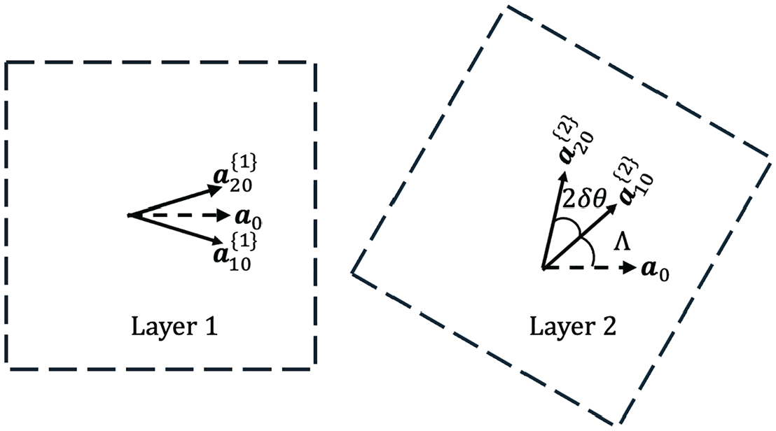
The forming of moiré pattern by two overlapped cell wall laminae: the two layers have a finite relative rotation by an angle Λ while the half waviness angle
while in the second layer, CMFs are represented as a set,

Whereby

It is clear that

for the formulation of the moiré pattern.

where
The explicit expression of moiré vectors

where the components of the unit tensor

where the symbol

in which

The example of moiré pattern and moiré vectors are presented in Figure 3.
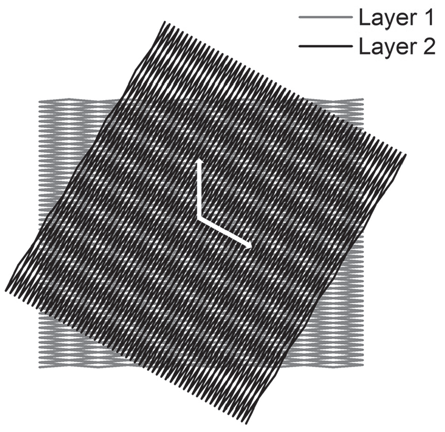
The moiré pattern formed by two overlapped cell wall laminae where the contact model is used with the half waviness angle
The sets

where
Then the moiré vectors on

The explicit expression of moiré vectors

where

where

in which

We have the following two relations between the moiré vectors in

which is in the same form of the relation between the normalised fibre direction in

Analogues to
The moiré angles,

respectively. It can be proven that

2.1.3. Description of the contacts
In the reference configuration, the contacts, which physically are the thin patches of xyloglucan between CMFs bundles, are considered as a discrete point set,
It is proposed that the point set of contacts
On the other hand, the structural tensor
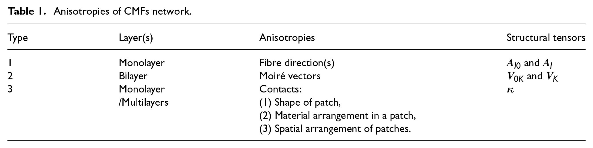
2.1.4. Summary of the anisotropies of CMFs network
The anisotropies of CMFs network introduced in the above discussion are summarised in Table 1.
Anisotropies of CMFs network.
Mathematically, the structural tensors
On the other hand, the details of formulation related to
2.2. Kinematics in principal stretches
The polar decompositions of

where

respectively.
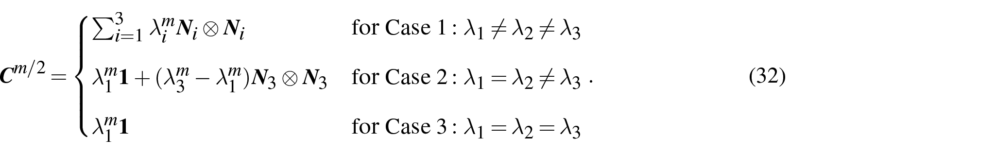
By using the spectral theorem for symmetric positive definite tensors,

where

in which

respectively.
Accordingly, equation (19) indicates that

And the spectral decompositions of

respectively, where

Consequently, from equation (19),

For convenience, a structural tensor,

Then, for example,
Noting that, although

and

if and only if

This indicates the singularity issue,
2.3. Generalised strain measures
In either
In order to effectively correlate the potential experimental data with, say, a power law of any principal stretch, the generalised strain measures are introduced as [31],
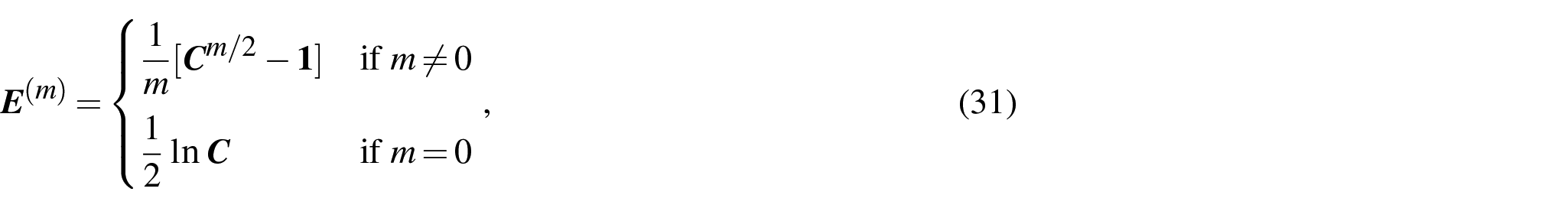
where, by using equation (20), the expression of
2.4. The derivative relations between
and
Besides the tensorial relation (20), the derivative relations between
By assuming

To avoid over complexity in the expressions, we simply use
First, the derivatives of

which requires that
Second, the calculation of
2.4.1. Case 1:
Differentiation of equation (20) in both sides reads

Since

2.4.2. Case 2:
In this situation,

Hence, using equation (35) we have

and

where the relation,

is derived from equations (25) and (27).
2.4.3. Case 3:
We write equation (20) as

Hence

3. Constitutive theory
3.1. Free energy functions of the cell wall as a fibre-reinforced material
Let us consider the free energy functions (i.e. free energy densities per unit volume) on


in which Ŵ,
For conciseness, it is useful to introduce a function

and calculate its derivative with respect to the stretches as

3.1.1. Specification of the function
In order to model the matrix composed of hemicellulose and pectins, we consider two features of the cell wall matrix. First, the recent reports referred the pectins as a hydrogel gel [1,5]. Second, the plant cell wall subjected to dehydration may still offer the useful insight into its microstructure [33]. The two features suggest that a matrix model capable of modelling a wide range of volumetric deformation from nearly incompressible to highly compressible may provide a broad support for exploiting and interpreting experimental data.
Therefore, a specification of the free energy function Ŵ of the wall matrix in equation (42) is adopted from the isotropic compressible model proposed by Storåkers [25]:
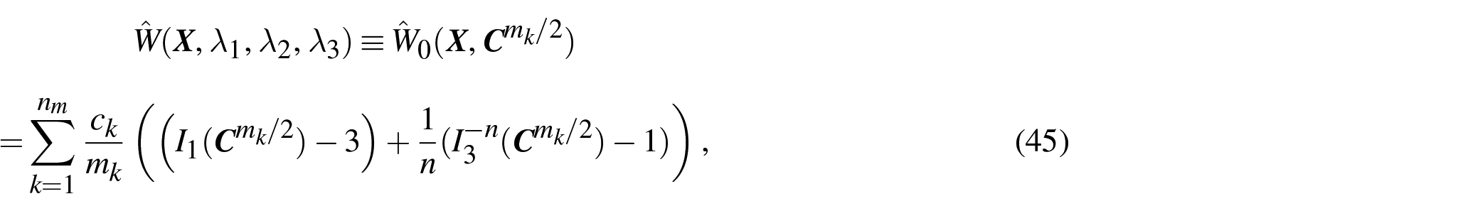
where

Hence, Ŵ in equation (45) may be expressed explicitly in terms of

Accordingly, the specifications of

and

3.1.2. Specification of the functions
and
The free energy function
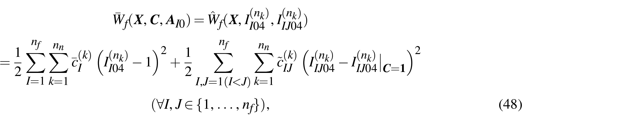
where
Case 1:
Using equations (20) and (27), it is defined that

and

respectively. Noting that the two specifications of
Case 2:
In this case,

and

respectively.
Case 3:

and

The function
3.1.3. Specification of the function
It is supposed that

where
The two functions,

where

where
Case 1:

Case 2:

Case 3:

3.2. Stresses
The second Piola–Kirchhoff (PK2) stress,

respectively. According to the decomposition of the total free energy function in equation (42), the total stresses

where

are the matrix part, fibre part, moiré part, and contact part, respectively, of
3.2.1. Matrix part of stresses
Using
Based on equation (27), we have the relations
3.2.2. Fibre and moiré parts of stresses
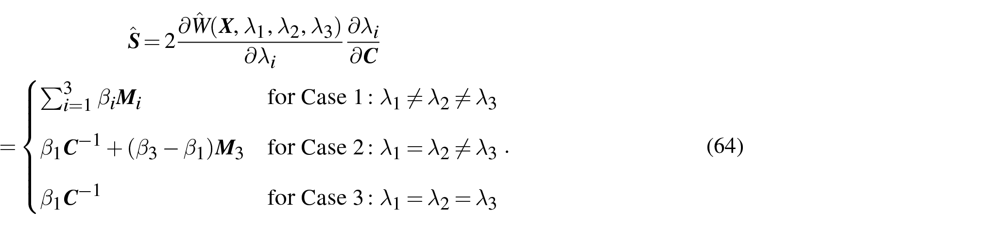
Using equation (63)2 together with equation (48), we write the fibre part of the PK2 stress as
To be consistent with the formulation of the matrix part of stresses in equation (64),
Case 1:
First, the term

where
Second, the coupling term

Case 2:
Similarly, the term
where we already use the relation,

and
For the coupling term
Case 3:
In this case, both terms,

and

where
3.2.3. Contact part of stresses
Using equations (55) and (57), equation (63)4 indicates that

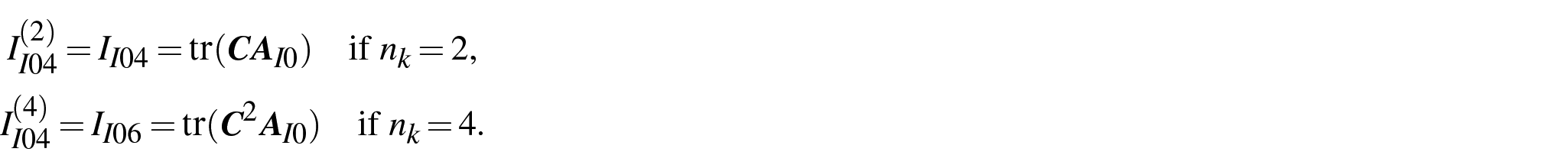
The first term in r.h.s of equation (74) is calculated in a form similar to equation (64):

in which, similar to equation (47),

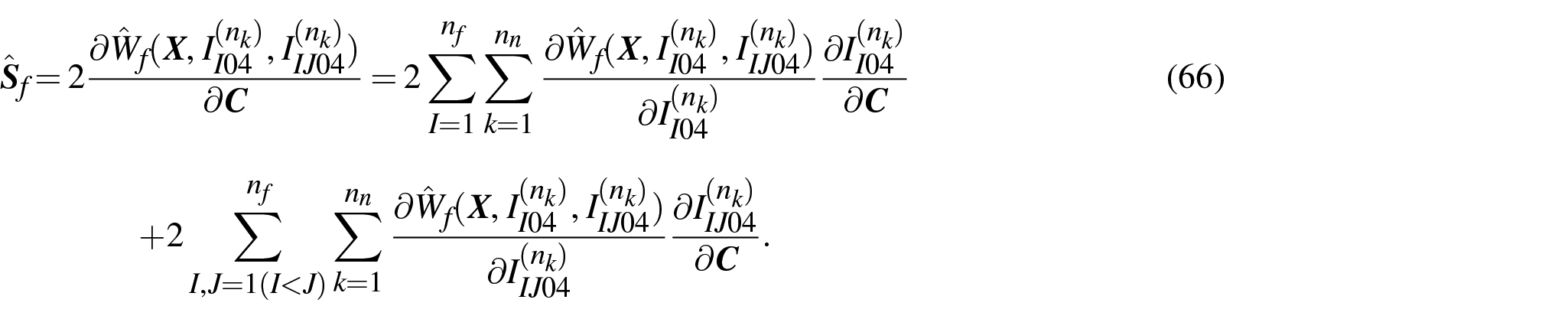
The second term in r.h.s of equation (74) is calculated in a form similar to equation (66) as

The term
Case 1:
Similar to equation (67), we have

Case 2:
In this case, similar to equation (69),
Case 3:
Similar to equation (72), the expression is

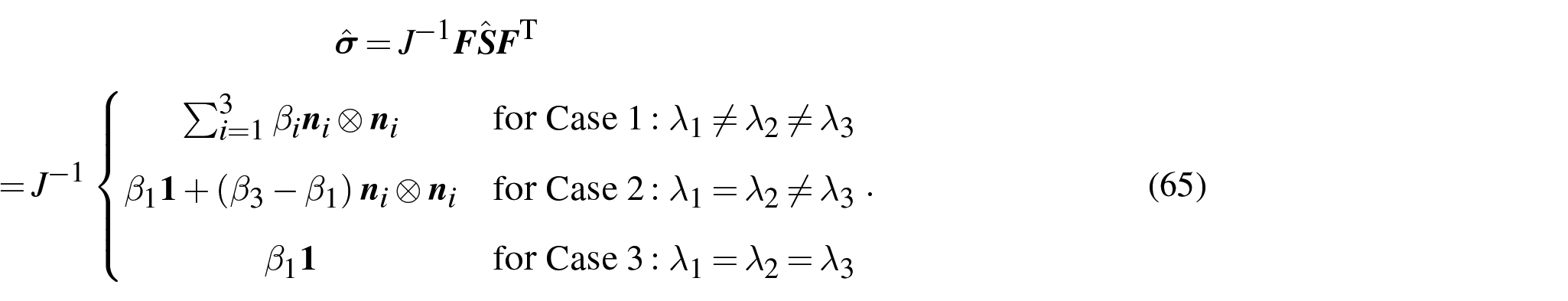
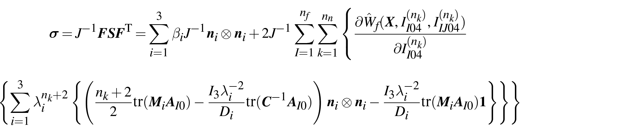
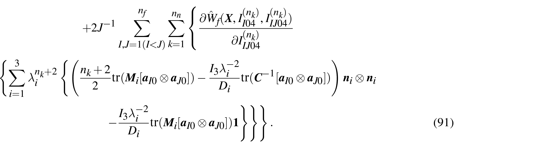
Acorrdingly, Cauchy stress
3.3. Tangent moduli
Besides stresses, the tangent moduli play the key role in numerical modelling, e.g., FEM. The tangent moduli on

while the tangent moduli

According to the decomposition of free energy density (42) or the decomposition of stresses (62), the total tangent moduli ℂ and

where
are the matrix part, fibre part, moiré part, and contact part, respectively, of ℂ, while
The detailed calculation of tangent moduli ℂ and
4. Simple shear of cell wall lamina
One of the prevailing hypotheses of cell wall growth mechanisms is that shear deformations plays the key role, biologically and physically, to achieve the expansive growth of the cell wall [1].
Based on this hypothesis, Boudaoud [13] and Dumais et al. [14] proposed the growth models exactly analogues to the conventional isotropic
However, analysis of growth at cell wall structural scale mainly provides the solution of wall morphogenesis, which is simply the output of the growth hypothesis. As the shear-induced growth hypothesis was qualitatively presented in biological literature as the collective mechanisms at the material scale of cell wall (e.g. sliding of CMFs) (see Cosgrove [1] for example), it is of great interest to formulate and examine the wall material behaviours under shear deformation for quantitatively representing the biological hypothesis.
Noting that cell wall is a multilayer (laminae) composite structure in which each layer (lamina) can be modelled as a fibre-reinforced material as illustrated in Figure 1. Hence, rather than wall laminae structure, let us consider one representative wall lamina corresponding to Figure 1. Based on the preceding discussion about the hyperelastic modelling of the plant cell wall, we formulate the elastic relation between the simply shear and von Mises stress (equivalent to
4.1. Kinematics of the simple shear deformation
Let us consider the simple shear deformation [26,27,31,36],

where γ is the in-plane shear of one lamina of the cell wall placed on the

The specification of equation (21) reads

Solving equation (86) gives the principal stretches:

By using equation (30),

The specifications of

It is straightforward to show that
By using the relation (25), i.e.,

4.2. Stresses
As of interest is a single lamina, the moiré part and contact part stresses,
Consequently, with the help of the relation
The expressions of
4.3. Example: the contact model of CMFs network as a fibre reinforced material
Based on the theoretical analysis and data fitting reported by Huang et al. [20,21], a neo-Hookean model of matrix is taken as the example to demonstrate the present method. In this model, the free energy functions,

and

And let us consider the two-families of fibres, i.e.,

for specifically modelling the contact model of CMFs network.
4.3.1. Cauchy stress
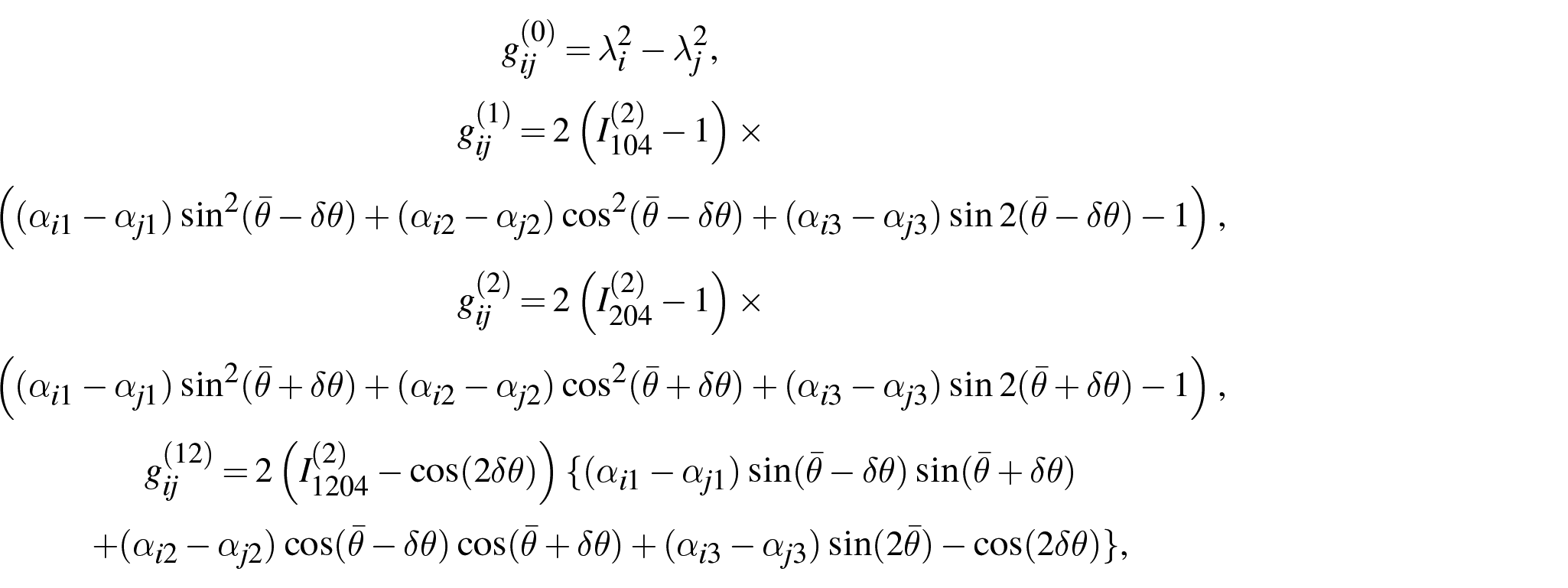
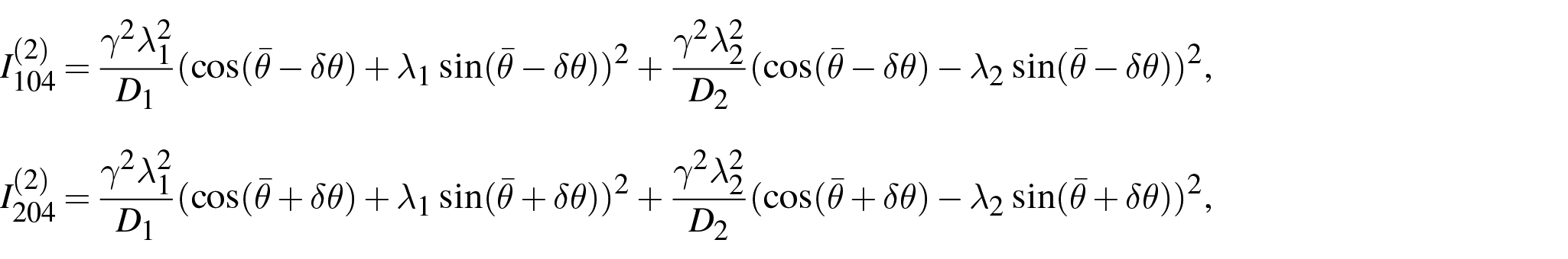
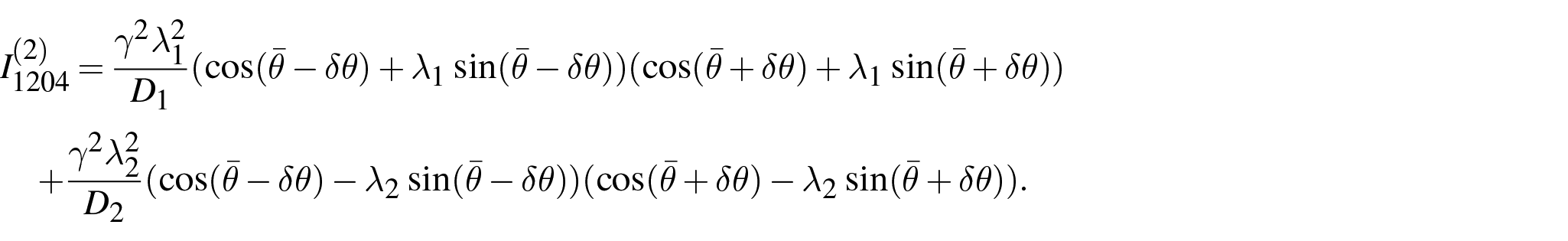
Based on the above setting of the material model, the total Cauchy stress in equation (91) may be further specified as

where the scalar functions
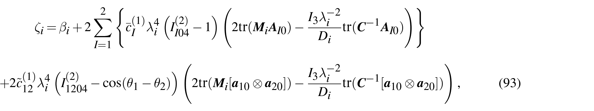
and
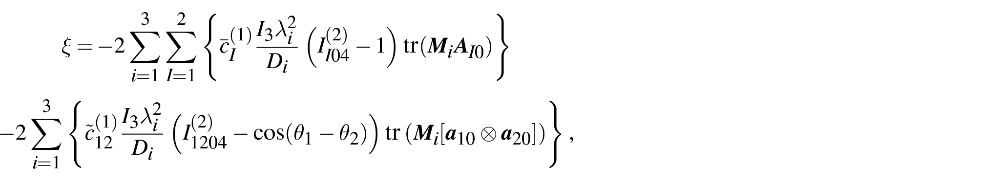
in which,

and from equations (58), (50) and (175) (for
Furthermore, by using the relations (175) and (177) (for
where the coefficients
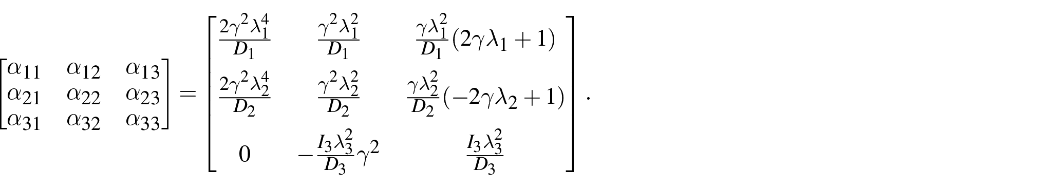
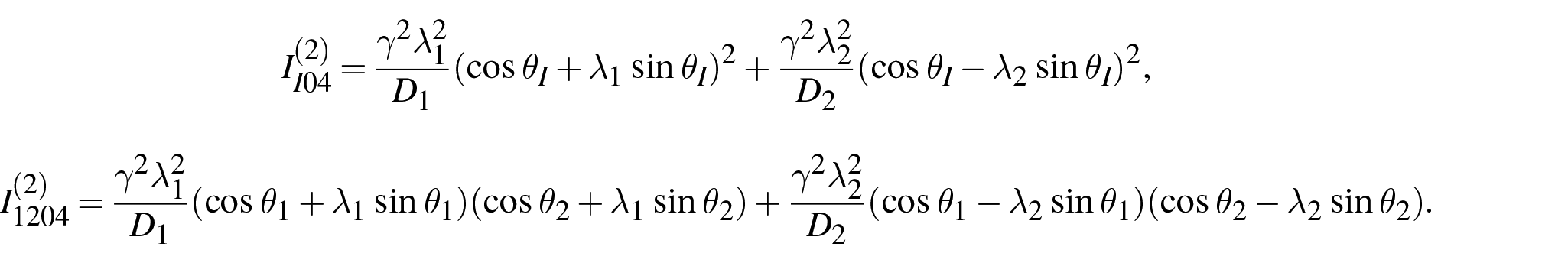
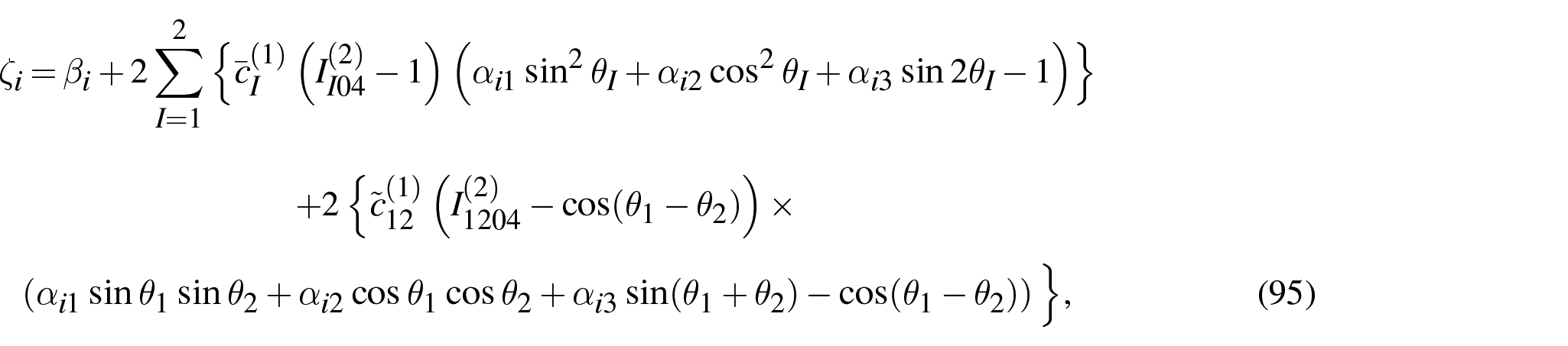
4.3.2. von Mises stress as the function of
As aforementioned, according to growth models in Boudaoud [13], Dumais et al. [14], von Mises stress may be considered as the indication of growth criterion and measure. By using the formulation of principal stresses, von Mises stress, denoted as

From equations (94) and (95), it is clear that, for a pair of

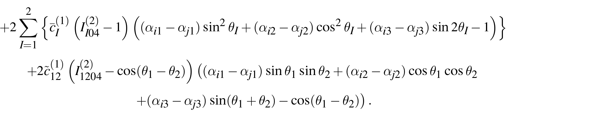
Let us introduce

where

where
in which
and
The functions
4.3.3. Numerical results
It is of interest to examine the contribution of each of the functions,
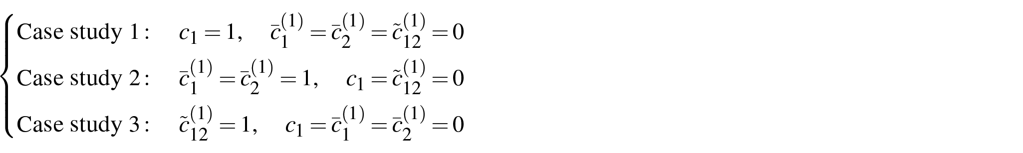
for the expression (97). The Case studies 1, 2 and 3 characterise the model behaviours of the matrix part (
First, we examine the model behaviour of the matrix part by using Case study 1. The change of
The typical
Second, the Case study 2 is conducted to examine the behaviours of the uncoupled part of the fibres. The curves of
The typical
Figure 5(a) shows the results of the specific fibre arrangements of
Figure 5(b) shows two features of
The prominent feature of the results of
Third, the Case study 3 is studied for examining the behaviours of the coupled part of the fibres. The
The typical
For more precisely understanding the stability/instability of

The typical
Figure 7(d) is consistent with what is directly observed in Figure 6 that only the
In summary, the numerical study shows that, by adding the coupling term representing the waviness and contacts of CMFs, the stiffness and stability of cell wall material may have much more variations in the variable space of
5. Moiré pattern in tensile stretch of cell wall
Uniaxial or biaxial tensile stretch testing is the important method to understand material properties. In the remaining part of this study, we present the mathematical analysis of cell wall related to tensile stretch which, to the author’s best knowledge, has not been reported in the literature.
Let us consider a macroscopic tensile deformation,

is applied on bilayer laminae of cell wall.
Given
Then counterpart in
Accordingly, moiré vectors in
Consequently, the normalised moiré vectors
which are demonstrated in Figure 3. The corresponding moiré angles ω in

It should be emphasised that the above results are based on the assumption that both layers are subjected to the same deformation
It is noted that
6. CMFs’ microscopic motion under macroscopic tensile stretch
6.1. CMFs’ microscopic motion problem
Zhang et al. [4] reported the experimental observations of CMFs’ motions under elastic tensile stretch which cannot be explained by the conventional passive angular reorientation model of CMFs, as stated by those authors. One of the observations was the lateral separation of two adjacent CMFs which were aligned in the transverse direction of stretch (see Figure 2(c) of Zhang et al. [4]). The observation may be modelled as a problem shown in Figure 8. The two CMFs contacted to each other before being stretched macroscopically (see Figure 8(a)). When the stretch is applied, the two CMFs are separated from each other as indicated by the evidence of the detaching of CMFs from the initial contact point (see Figure 8(b)). This may not be explained by the conventional fibre-reinforced model using the perfectly bonding assumption.
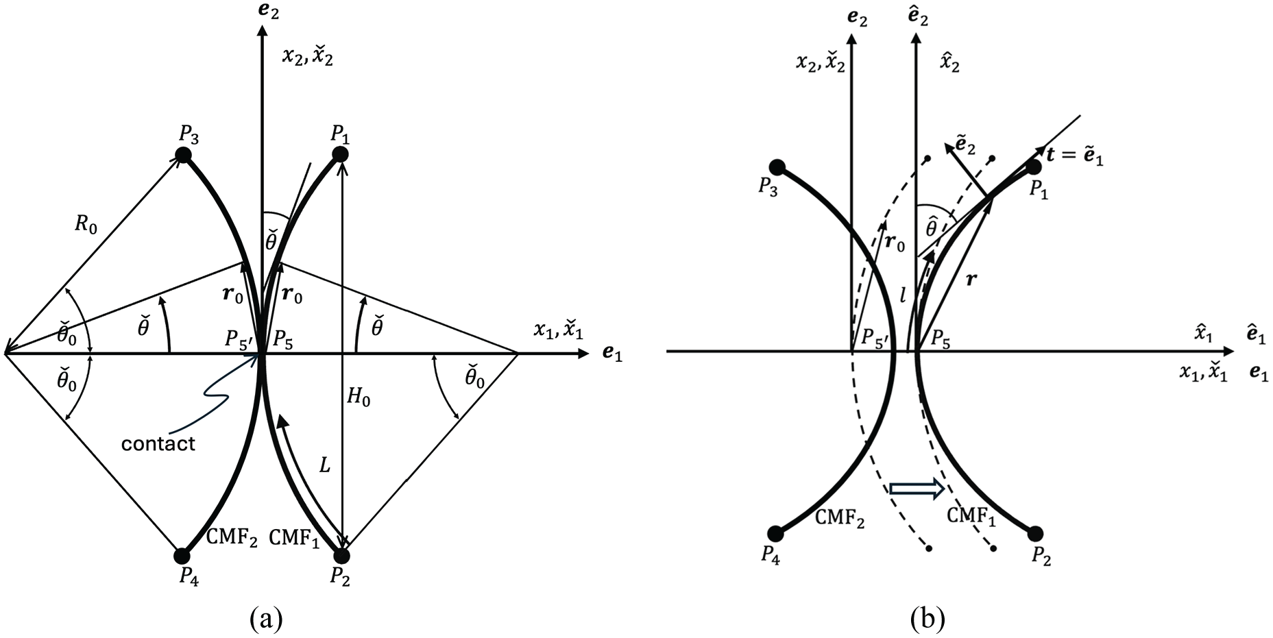
Microscopic separation and relative motion of CMFs under macroscopic tensile stretch: (a) reference configuration of two CMFs, (b) solid lines represent the deformed configuration of CMFs while the dash lines are the reference configuration of CMF
For addressing this problem, we propose a micromechanical model of the CMFs’ motion based on the preceding discussion of the contact model of cell wall. As shown in Figure 8(a), the centroids of the two CMFs are assumed to be depicted by the arcs of two circles of radius
where
We restrict our attention to the situations that the cross-section of the CMF was proposed to be either rectangular or ribbon-like due to the arrangement of cellulose molecules [40–43]. And it is assumed that the principal directions of the cross section of CMFs are aligned in a proper way so that the microscopic motion and bending of CMFs only take place in the principal plane
6.2. Macro-micro-kinematical relations
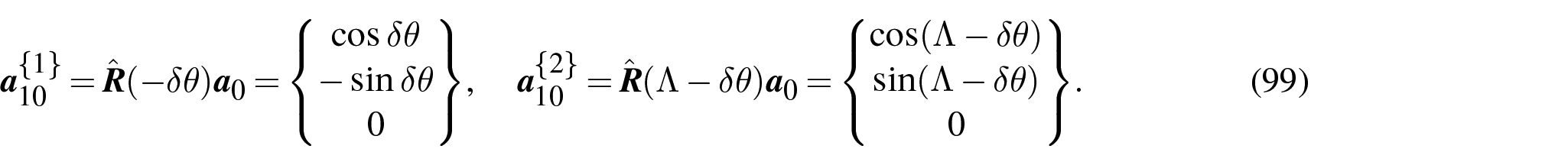
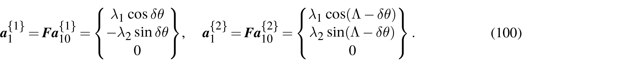
Let us consider the points,
In the case that the contact points,
Let us first consider a macroscopic tensile stretch (98). The corresponding macroscopic deformation is

The perfectly bonding constraint is imposed on the end points of CMFs,

Hence, the displacements of the point

For the specified problem under consideration, we only need to consider the two relative displacements in the principal directions,


Furthermore, the perfectly bonding constraint is also imposed on the rotation of CMFs at the end points
where the macroscopic angle
Hence the current fibre direction at
where

Due to symmetries, we have

This determines the microscopic fibre angles,

Together, the microscopic motion of CMFs (displacements and rotations), at the end points
6.3. Equations and solution of the microscopic CMFs motion
Our purpose is to calculate the microscopically relative motion between the contact points,
Due to the symmetry of the two CMFs, only the arc
Then let us consider such a rod bending problem of the step 1: the end point

while the point

Since

Hence the problem of solving the displacement of
To calculate the deformation of the CMF subjected to the above all-kinematics boundary conditions (117) and (118), we may re-expressed the above bending problem as follows: while keeping all other boundary conditions the same as in equations (117) and (118), the CMF is subjected to a unknown force, f, at the point
The deformed local configuration of the CMF in the moving frame
where l is the arc length parameter of the deformed CMF. Then the tangent vector of the arc is

Then we have

Using
it is straightforward to calculate that

The negative sign is due to the increasing direction of

or

The equilibrium equation of the CMF is

where

By introducing the constitutive law of CMFs,

where E is Young’s modulus of CMF and

As aforementioned, the unknown force

The integration of the above equation gives
for

The boundary condition of
where
The two equations (135) and (136) can determine

Here we use the relation that both
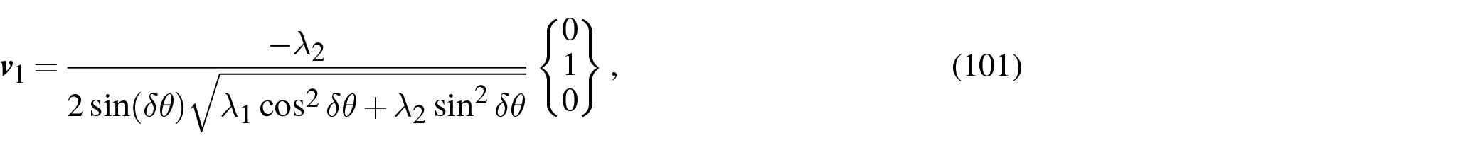
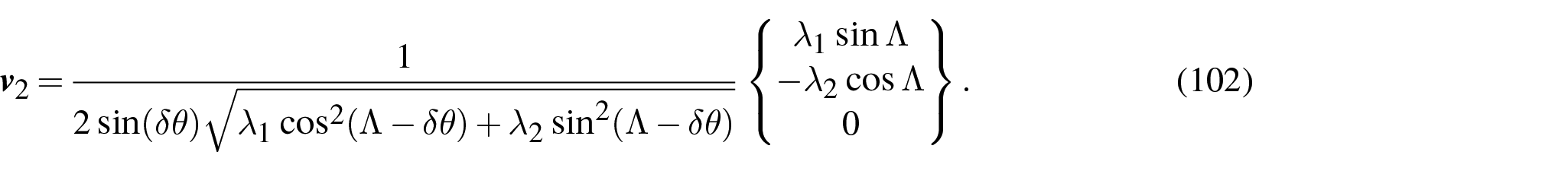
Consequently, the displacement of the point

which gives the motion of

Due to symmetry, the displacement of the contact point
By imposing the subsequent rigid body translation

In the case that
7. Potential growth mode
The conventional kinematical growth theory has been relying on the so-called intermediate configuration, denoted
In the tethering model of cell wall, the growth was considered to be dominated by the matrix both physically and mathematically. The matrix is in an amorphous state. Hence, unlike plasticity theory where crystal plasticity provides micromechanics interpretation for
In contrast to the tethering model, the contact model suggested that CMFs play the dominant role in both the mechanical and growth of the cell wall. Hence, the motion of CMFs, which is more likely to be observed than that of matrix components, may provide the experimental evidences for the micromechanics model of growth.
Based on this consideration, according to the discussion in Sections 5 and 6, we may consider mathematically a potential growth mode of the contact model of cell wall. It is assumed that, due to the loosening of one representative contact, say point
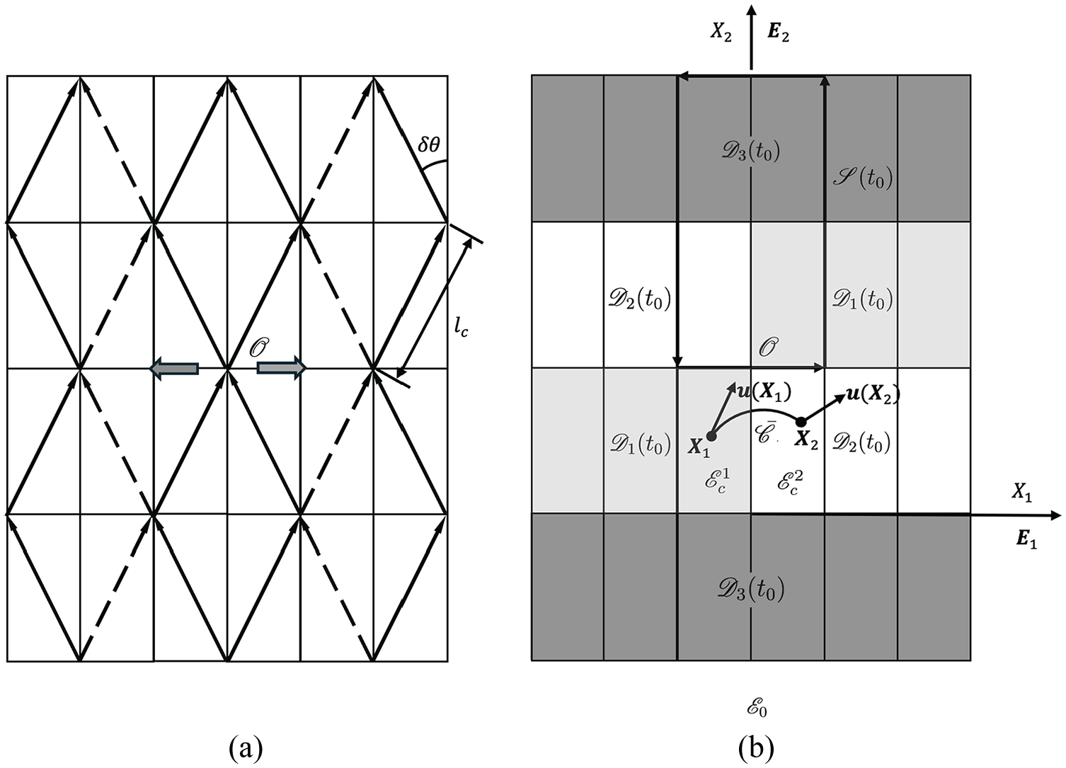
Reference configuration
7.1. Analysis of the growth mode in the intermediate configuration with Burgers vector
Let us consider at the reference time
7.1.1. CMFs’ motion and shear of ‘crystals’
As discussed in Section 6, two CMFs may detach and separate from each other due to the loosening of the contact at the point
As the contact of two CMFs at
The growth deformation gradient
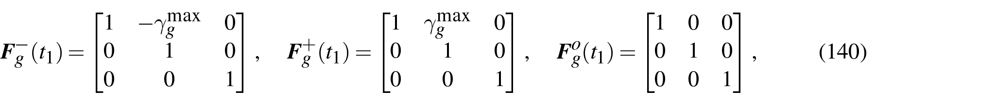
respectively, for the different ‘crystals’ located in three different domains,
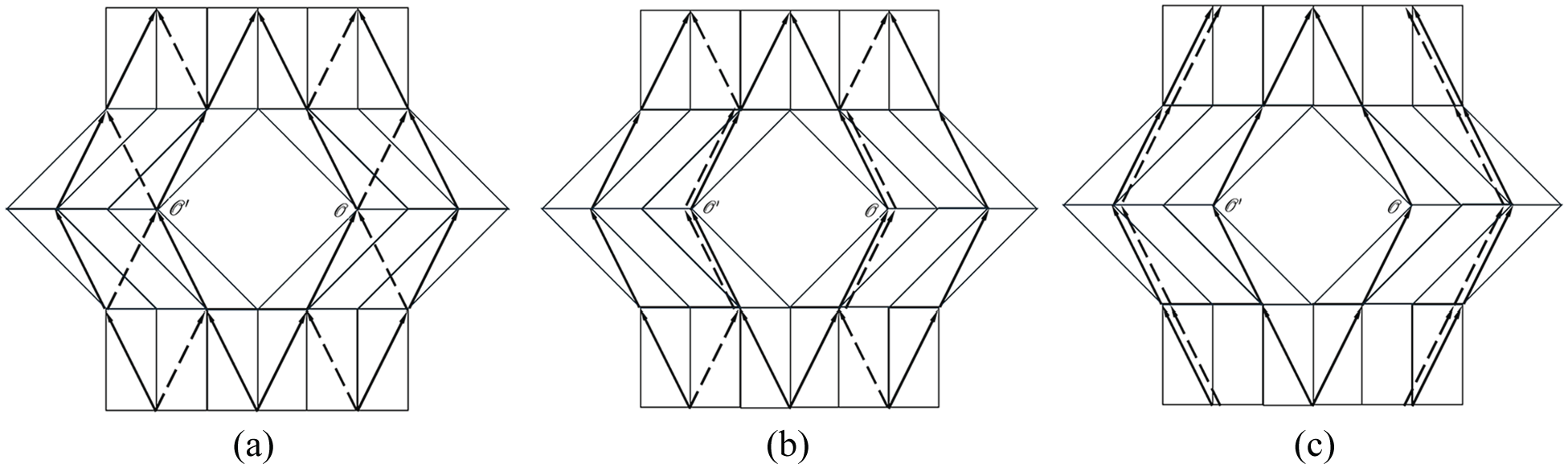
As shown in Figure 11(a), it is possible to define the single-valued deformation,
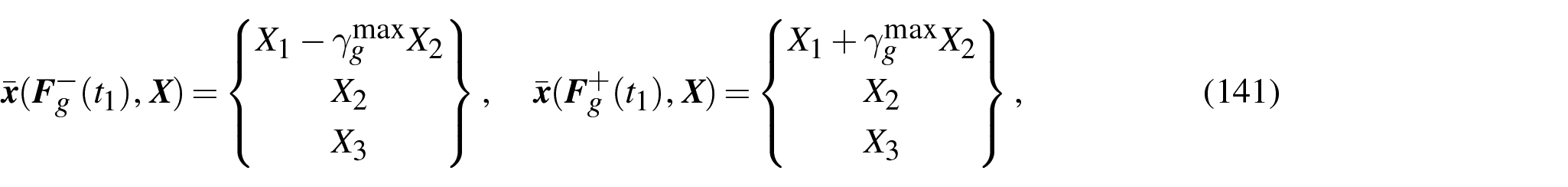
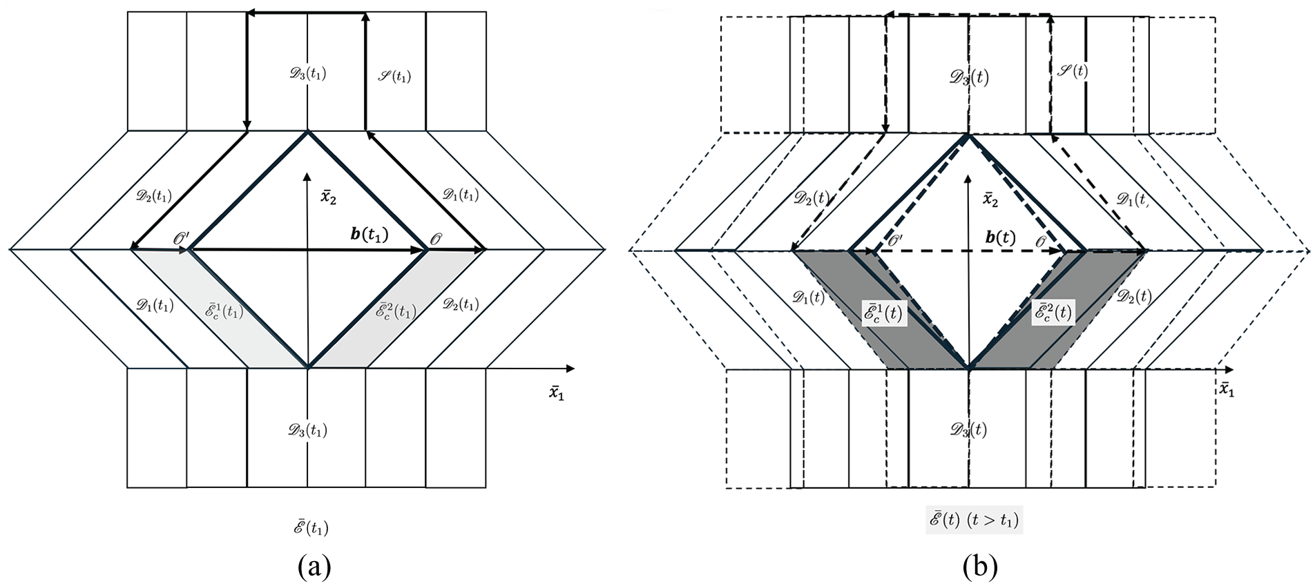
Burgers vectors
which give the deformed configurations of the ‘crystals’,
Noting that there is a jump of
This incompatibility is clearly depicted by the empty rhombus gap spanning between

where

where
7.1.2. Volumetric growth of ‘crystals’
Bearing in mind that
Let us consider a volumetric growth, which is an in-plane expansion in the

where
where
Accordingly, the total deformation,
which is also highlighted by grey colour in Figure 11(b) to show the increase of the volumes.
In this case, the magnitude of Burgers vector,

Noting that the inextensibility of CMFs requires that the point

That is

To achieve the above requirement, the shear

This may be interpreted as the relaxation of shear deformation due to volumetric growth.
7.2. Torsion of the growth mode in material space
Besides Burgers vector, the torsion in material space, denoted
Let us consider moving a vector

which gives the linear relation if omitting the higher-order term,

where
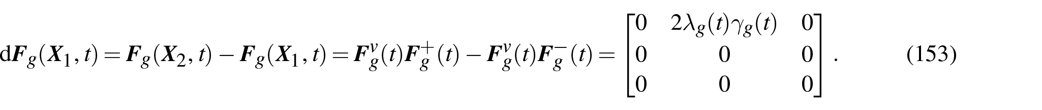
Hence,
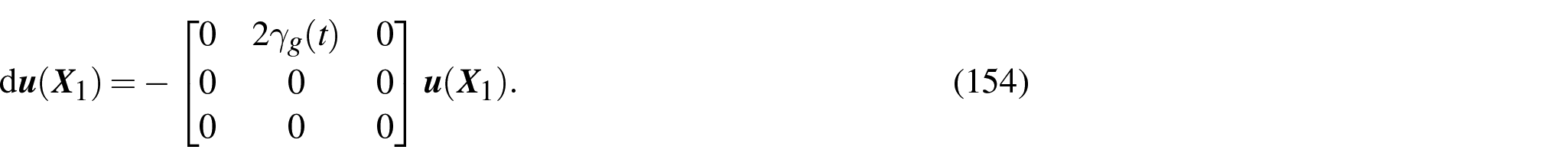
On the other hand, according to the definition of connection in non-metric space, we may introduce

where
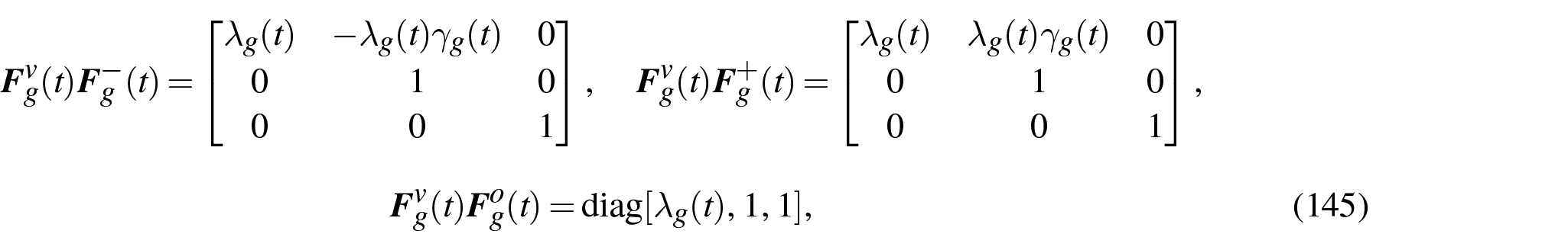
By comparison between equations (154) and (155), the only non-zero term in equation (154) indicates that

while all other components of

where

does not vanish unless
7.3. Discussion
Hitherto, we give the detailed analysis about the scenario in which ‘crystals’ in the representative element
8. Conclusion
The recent development of the research on the plant cell wall has greatly enriched the understanding of (1) the structures and roles of the components of the cell wall (e.g. CMFs, hemicellulose, pectins) and (2) the interaction between those components. Especially, the knowledge about the construction of the CMFs network and its relations with other component, which is the key to understand both the mechanical behaviours and growth of the cell wall, has shown substantial improvement. This study is aiming to propose the continuum model reflecting those recent progresses and to provide a unified mathematical and numerical framework for quantitative modelling. The proposed fibre-reinforced material model may cover both the more conventional tethering model and the recently proposed contact model of the CMFs network in a unified framework. This may provide a method for the (1) quantitative modelling and (2) model/hypothesis validation and comparison if the experimental data are available.
In addition to the anisotropy of CMFs (physical fibres), the potential anisotropies arising from the moiré pattern and the contacts between CMFs are taken into account. The moiré pattern may shed new light on the modelling of the interaction between neighbouring layers of cell wall laminae. On the other hand, the anisotropy due to the contacts may enrich the model by taking into account the shape of and the material arrangement in the single contact and the spatial arrangement of a group of contacts. Together, it is demonstrated that the extended description of anisotropies may lead to the more sophisticated cell wall model to capture the material behaviour beyond the more conventional fibre-reinforced model of cell wall.
The simple shear problem is taken as a case study to demonstrate the proposed modelling framework since shear deformation has been widely considered as one of the key mechanisms for cell wall growth. The numerical results show the consistence with the experimental observations of the CMFs arrangement in the growing plant cell wall, and also indicate the potential mechanisms which the cell wall may use to regulate its stiffness and stability for achieving a sustainable growth.
Then the tensile stretch is studied for a variety of problems. First, the moiré pattern under the tensile stretch is presented, which may indicate the principal directions to which CMFs are separated. Second, the motion of the adjacent CMFs after separating from the shared contact is discussed by using the rod theory. Third, a potential growth mode is suggested based on the separation and motion of CMFs. The two mathematical tools, Burgers vector and torsion in material space, are applied to analyse the potential incompatible growth configuration. Again, the analysis of cell wall under tensile stretch provides some insights which may be out of scope of the more conventional fibre-reinforced model of cell wall.
As the details of stresses and tangent moduli are provided, this study also provides the formulations readily to be implemented in numerical methods like finite-element method for broader applications.
Footnotes
Appendix 1
Appendix 2
Appendix 3
Appendix 4
Acknowledgements
The author appreciates the reviewers’ very helpful comments for improving the quality and presentation of the manuscript. The author declares that there is no research funding supporting this research.
Author’s Note
This paper was initiated for dedication to the memory of Professor Zhong Wanxie.
Funding
The author(s) received no financial support for the research, authorship, and/or publication of this article.