
Abstract
This paper deals with mesoscale analysis of masonry structures, which involves fracture propagation in brick units as well as along the masonry joints. The brick–mortar interfaces are incorporated in standard finite elements by employing a constitutive law with embedded discontinuity. Macrocracks in bricks are modelled in a discrete way using the same methodology, without any a-priori assumptions regarding their orientation. The proposed approach is computationally efficient as it does not explicitly require the discretization of joints. The accuracy of the approximation is first assessed by comparing the solution with a detailed mesoscale model incorporating interface elements. Later, a numerical study is conducted involving simulation of various experimental tests on small masonry assemblages, as well as single-leaf masonry walls, with running bond pattern, subjected to in-plane loading. The results clearly demonstrate the predictive abilities of the proposed simplified approach.
1. Introduction
Masonry systems are among the oldest types of engineering structures that include historical heritage and strategic buildings. The masonry assemblies have a significant compressive strength; however, their shear and tensile resistance is limited, which is of particular concern in case of structures that are subjected to lateral loads induced by seismic events [1, 2]. Numerical investigations into the mechanical behaviour of existing masonry structures enable the detection of vulnerabilities and assist in the design of retrofitting techniques [3]. Computational models are generally developed either at mesoscale or at macroscale. The former approach considers the geometric arrangement of masonry units and mortar joints, and often incorporates the brick–mortar interfaces [4–7]. On the other hand, in macroscale approach, the masonry is perceived as an equivalent homogeneous and anisotropic continuum [8–11]. Homogenization procedures [12–14] or multiscale approaches [15–18] are typically considered as a bridging between the two scales. In general, despite the existing body of scientific research, the development of reliable and efficient strategies for modelling mechanical behaviour of structural masonry still remains a challenge [19–21].
The macroscale modelling of nonlinear behaviour of masonry assemblies usually involves continuum approaches, such as plasticity, damage mechanics and nonlocal damage plasticity [22–27]. In this case, the relevant data come from experimental investigations. The latter have been conducted in the past not only on brick masonry but also on concrete and stone panels [28–30]. However, the tests at this scale are expensive and require a broad range of loading and boundary conditions. More importantly, in case of existing historical and strategic masonry buildings, acquiring specimens that are representative in terms of assessment of macroscopic behaviour is virtually impossible. On the other hand, the mesoscale models incorporate only the mechanical properties of individual constituents. This information can be acquired in situ without affecting the integrity of existing structures, as it entails standard material tests. The main challenge in mesoscale models of masonry is incorporation of strain-softening response describing localized deformation associated either with sliding/separation along the brick–mortar interface or with cracking of bricks/mortar. In general, the nonlinearity in mechanical behaviour of masonry is triggered by displacement discontinuities that develop at the interface between bricks and mortar [31] in either tensile or shear failure modes, i.e., Mode I and Mode II of crack propagation [32]. The latter has motivated the development of simplified mesoscale models that usually consider bricks as an elastic continuum [33], while accounting for the interface behaviour through plasticity [34–37] or combined damage-plasticity models [6, 38–40].
The current paper addresses the issue of modelling of damage propagation in structural masonry. The analysis employs a mesoscale approach in which the brick–mortar interfaces are considered as being embedded in the adjacent intact material and their mechanical properties are accounted for through a constitutive law with embedded discontinuity [41, 42]. The main objective here is the verification of the accuracy of this simplified approach against other methodologies, as well as its validation against the existing experimental data. For this purpose, a series of numerical simulations are carried out involving various structural components of masonry, such as couplets/triplets, beams and full-scale masonry walls. The analysis is restricted to in-plane loading conditions and deals with a single-leaf running bond arrangement. The fracture patterns involving both the sliding/separation along brick–mortar interface as well as formation of discrete macrocraks in the brick units are investigated.
2. Mathematical formulation
A detailed mesoscale analysis of masonry requires discretization of the mortar region to account for development of cracks within this domain, as well as modelling of the brick–mortar interfaces (Figure 1). The simulations typically employ a graded unstructured mesh together with a set of interface elements. This impairs the computational efficiency, especially for larger structures, and may lead to numerical instabilities.
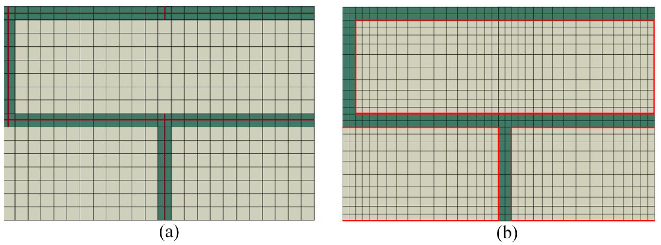
Mesoscale finite element model of masonry. (a) Elements with embedded brick–mortar interfaces (present approach). (b) Discretized brick-and-mortar units bonded via interface elements (detailed approach).
A simpler and pragmatic approach, which is advocated here, involves accounting for the presence of brick–mortar interfaces, which represent the weakest link in structural masonry, through a constitutive law with embedded discontinuity (CLED). Figure 1(a) shows an example of the finite element (FE) mesh with a schematic representation of the discontinuities embedded in elements representing the joints. It is noted that the orientation of interfaces is known a-priori and their mechanical response is defined in terms of a rate form of a traction—displacement discontinuity relation [43]. Thus, in this case, for elements containing interfaces the discretization is the same as in the adjacent bricks; however, the constitutive relation assigned is that based on the CLED formulation. For elements at the intersection of bed and head joints, the orientation of prevailing discontinuity will depend on the mode of failure. In this case, the components of traction along those two directions are used to check the failure criterion and the dominant mode is chosen. The orientation of the cracks in brick units can be assessed by specifying the orientation which maximizes the failure function or by employing the bifurcation criterion [44]. Their discrete propagation is then monitored via a level-set method.
In the present approach, the averaged mechanical properties of a referential volume containing a discontinuity are defined by a constitutive relation [41]

where

Here,
In this study, the brick material is assumed as elastic-brittle and the onset of failure is determined by Mohr–Coulomb criterion with Rankine tension cut-off [43]. Thus, in this case,

Here,

where

where
2.1. Numerical integration scheme
Given the state of stress at pseudo-time step n, i.e.,

Here,
The incremental form of the constitutive relation for the interfacial zone may be written as

where

where


which can be linearized to the form


Substituting the derivatives of the residuals leads to


where


where


which completes the numerical implementation of this approach.
3. Assessment of the level of approximation of simplified approach
To assess the accuracy of the simplified mesoscale approach, its performance was first verified against the solution based on a detailed model that incorporates interface elements. The examples presented here involve simulation of tension and biaxial compression–tension tests on half-scale masonry panels, similar to those used in experimental investigations reported in the work by Page [45]. The masonry arrangement consists of nine rows of bricks placed in a running bond pattern to form a panel 360 mm × 360 mm × 50 mm in size. The bricks have dimensions of 115 mm × 35 mm × 50 mm with a mortar thickness of 5 mm.
In the simplified approach, the brick–mortar joints were considered as being embedded in the adjacent intact material and were modelled using the CLED approach, namely, equations (1) and (2). The solution was then compared with a detailed model that incorporated all constituents, i.e., bricks, mortar and the brick–mortar interfaces. In this case, the interfaces were modelled using the surface-based cohesive contact algorithm [46]. The latter is primarily intended for describing the debonding process but can also incorporate the frictional behaviour. Here, the traction-separation/sliding laws were adopted in the form that is analogous to that in equations (4) and (5). This allows a direct comparison of both methodologies.
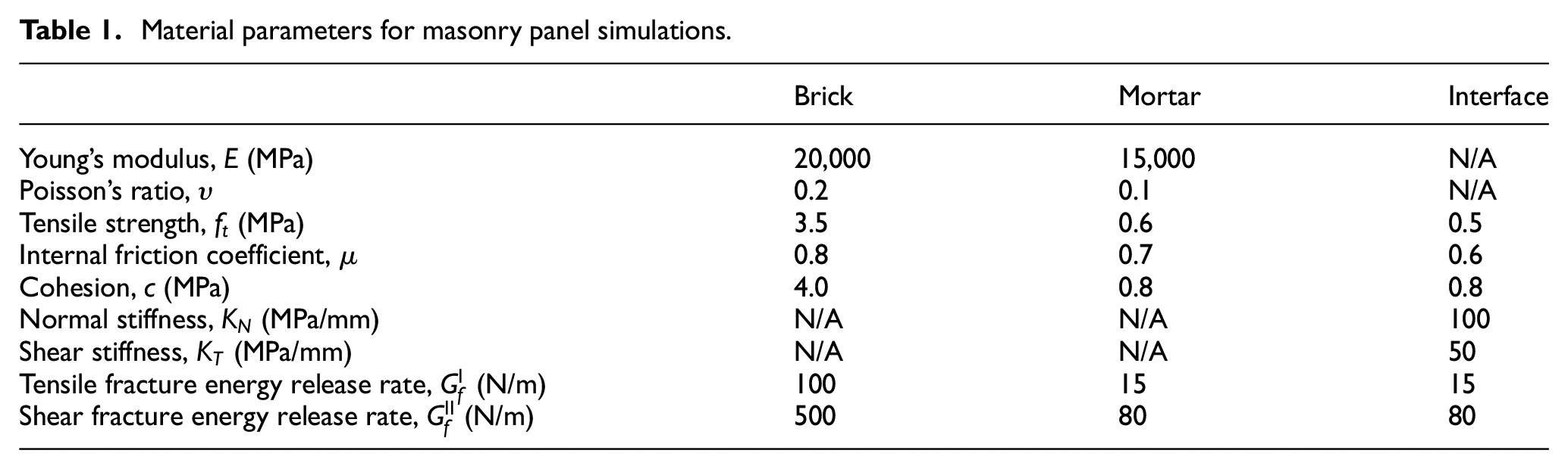
The simulations were carried out for uniaxial tension parallel to the bed joints and biaxial compression–tension with a fixed ratio of compressive to tensile load of 2. In the former case, the analysis was displacement-controlled, while in the latter case, a load-controlled scheme was employed. The geometry and the boundary conditions are shown in Figure 2. For biaxial test, the load was applied to the top and right boundaries of the panel, while the opposing surfaces were fixed in the direction of the imposed load. Figure 2(a) and (b) shows the FE mesh for both the proposed embedded interface approach and the detailed model including the mortar and the cohesive interfaces. It is noted that in the simplified approach, there are no specific restrictions on the element size. Thus, in this case, a coarser structured mesh can be employed, and the interfaces are embedded in elements which are at the location of mortar joints. The approach incorporates the internal length scale parameter, so that there is no systemic sensitivity to the mesh size/alignment. The material properties used in numerical analysis are summarized in Table 1. Note that for simulating biaxial compression–tension, the tensile strength of bricks was reduced to 0.5 MPa so that to allow the failure mode which includes the onset and propagation of cracks in the brick units.
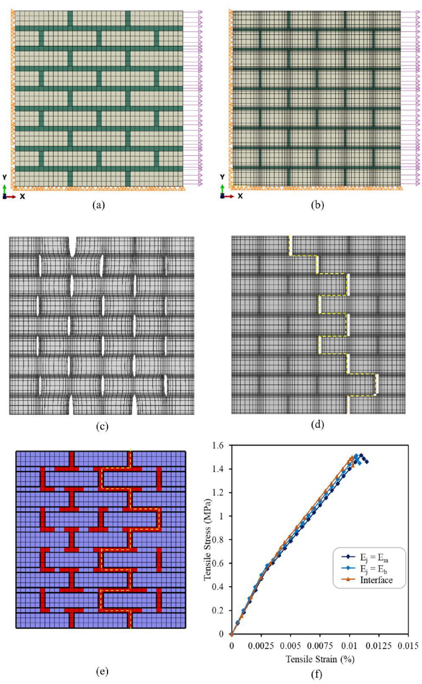
Finite element mesh and boundary conditions for (a) embedded interface approach and (b) detailed model with interfaces. (c) Initial and (d) final crack pattern for detailed model, superimposed on displacement field [note that the deformation scales are not equal]. (e) Crack pattern at the ultimate load for embedded interface approach. (f) Average stress–strain response of the panel.
Material parameters for masonry panel simulations.
The results for uniaxial tension along the bed joints are presented in Figure 2(c)–(f). Figure 2(f) shows the global characteristics in terms of average stress (i.e., magnitude of resultant reaction force over the area) and average strain. It is evident that the ultimate strength of the panel as predicted by the embedded interface approach is nearly the same as that obtained in the detailed model. It is noted that in the former case, two sets of simulations were carried out in which the joints were assumed to be embedded either in the brick material or in the mortar. In both settings, the CLED approximation was used, namely, equations (1) and (2). As expected, the elastic properties of the intact material (i.e., brick vs. mortar) had only a marginal effect on the global stiffness, while the ultimate load remained the same. For all cases considered, the failure mode involved a zig-zag pattern, in which the head joint experienced the tensile debonding, while the bed joint underwent a shear-induced failure. Figure 2(c) shows the initial fracture pattern obtained in a detailed model, superimposed on the scaled displacement field. A similar picture showing the displacement field at the ultimate load is provided in Figure 2(d). Note that the deformation scales in both these figures and not equal. The crack pattern obtained from embedded interface approach, which was similar to that of the detailed model, is provided in Figure 2(e).
As mentioned earlier, the simulations for biaxial tension–compression (BTC) were carried under load-controlled conditions. In this case, the ultimate strength of the panels was determined by examining the evolution of a stability parameter (SP) defined as the ratio of the second rate of internal work normalized with respect to the elastic solution

In general, the stability parameter remains within the range 1 ≥ SP ≥ 0, and SP = 0 implies the singularity in the global stiffness operator, i.e., the loss of stability.
The results of the numerical analysis are shown in Figure 3. In this case, the global fracture pattern involves the tensile failure in head joints combined with the onset and propagation of cracks through the brick units. The latter have been traced in a discrete way using the level-set method [43]. Since the ratio of compressive to tensile load is fixed here at a constant value of 2, only the load-displacement characteristics in tension are shown (Figure 3(d)). The general conclusions are similar to those that stem from the previous example. It is evident that the ultimate load at failure is similar in both the simplified and detailed models. Its assessment is not visibly affected by the elastic properties of intact material in which the joints are said to be embedded. The crack pattern, as shown in Figure 3(a)–(c), is also in a fairly good agreement for both approaches used.
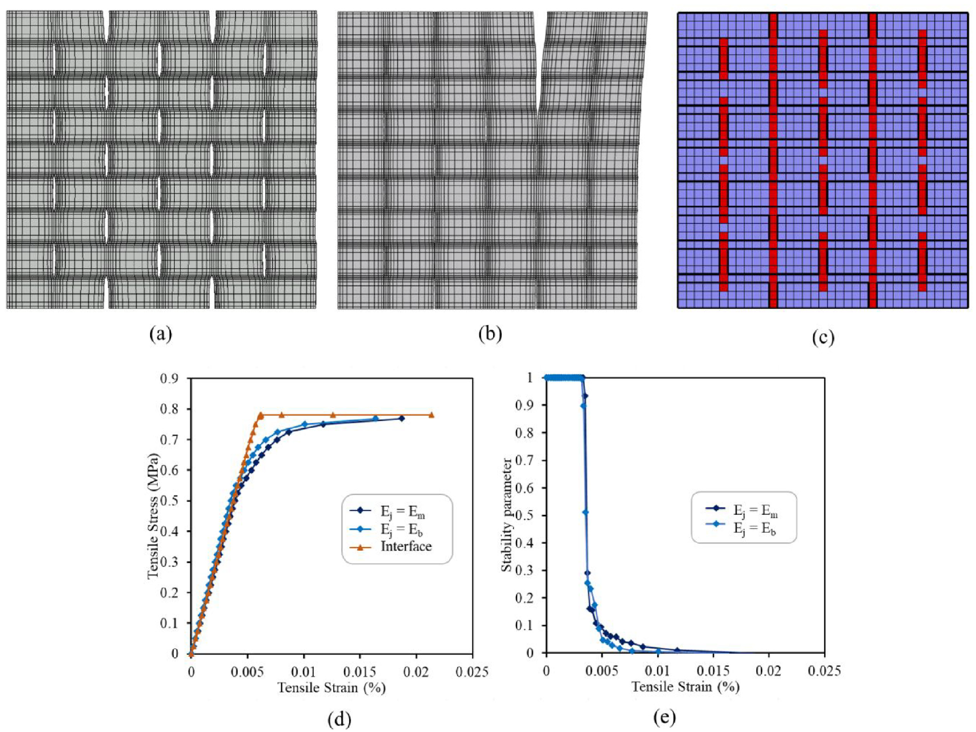
(a) Initial and (b) final crack pattern in detailed model with interfaces [note that the deformation scales are not equal]. (c) Crack pattern at the ultimate load for embedded interface approach. (d) Average tensile stress–strain response of the panel. (e) Evolution of stability parameter (SP), equation (14).
4. Numerical analysis involving small-scale experimental setups
In this section, a series of numerical examples is provided involving simulation of shear tests on masonry triplets/couplets. The tests incorporate different loading conditions, including cyclic loading, and the prevailing failure mode involves the propagation of damage along the brick–mortar bonds. The latter is modelled using the proposed embedded interface approach.
4.1. Simulation of shear tests on masonry triplets
The analysed tests were part of a study conducted in the work by Binda et al. [47], which involved a series of experiments on masonry assemblages and small prisms. The specific tests simulated here were the shear bond (triplet) tests. They employed a setup consisting of three bricks with dimensions of 170 mm × 120 mm × 55 mm that were arranged vertically and bonded together by two rows of 10 mm thick mortar joints. The masonry triplets were loaded in vertical direction to reach normal compressive stress of 0.12, 0.4, 0.8 and 1.25 MPa, respectively. Once the prescribed compressive load was attained, the horizontal displacement was applied to the middle brick to induce the shear failure in bed joints. During the test, the displacement field and shear loads were recorded. The geometry of the finite element model and the respective boundary conditions are shown in Figure 4(a). To simulate the experimental loading sequence, the bottom of the model was fixed in vertical direction and the target normal load was first applied to the top boundary. After this stage, the horizontal movement of the top and bottom bricks was also restrained, and the horizontal displacement was applied to the middle brick. The mesh consisted of a total of 726 eight-noded cubic elements. The simulations were carried out using material parameters consistent with those reported by Binda et al. [47]. In particular, the values of elastic constants for the brick material were taken as E = 2500 MPa and υ = 0.2. The components of the interfacial elastic stiffness moduli were assumed as
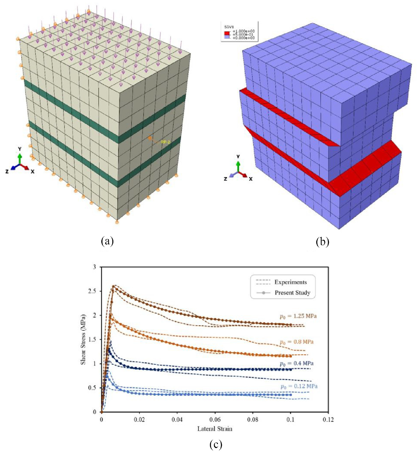
(a) Finite element mesh for masonry triplet under compressions and shear. (b) Deformed mesh showing the cracked elements with embedded interface. (c) Load-displacement response compared with experimental data.
To compare the numerical results to those of experiments, average shear stress and lateral strain were calculated based on the dimensions of the specimen. Figure 4(b) shows the deformed mesh including the elements with embedded interface representing the two rows of bed joints in the assembly. The predicted mechanical characteristics, corresponding to different values of normal compressive stress, are shown in Figure 4(c). Here, the results of the simulations are compared with the upper and lower limits of the experimental data obtained for different precompression stress values. It is evident that the predictions, in terms of the ultimate shear stress at different compressive loads, as well as the postpeak degradation of strength, are fairly consistent with the experimental evidence.
4.2. Simulation of shear test on a masonry couplet involving unloading–reloading cycles
The next set of simulations was focused on finite element analysis of experiments conducted in the work by Chaimoon [49]. The tests involved brick couplets subjected to shear displacement unloading–reloading cycles under a prescribed normal stress. The specimens included two bricks with dimensions of 230 mm × 51 mm × 110 mm separated by a layer of mortar with a thickness of 10 mm. The FE model consisted of 825 eight-noded cubic elements, as shown in Figure 5(a). To simulate the actual loading conditions, the bottom surface of the specimen was fixed in vertical direction and a vertical load was applied at the top to generate a normal compressive stress of 0.51 MPa. In the next step, the bottom surface of the specimen was fixed in lateral direction as well, and the shear displacement was applied at the top of the assembly. During the loading process, the shear displacement was reversed multiple times to induce unloading–reloading cycles until the maximum lateral displacement of 1.95 mm was reached.
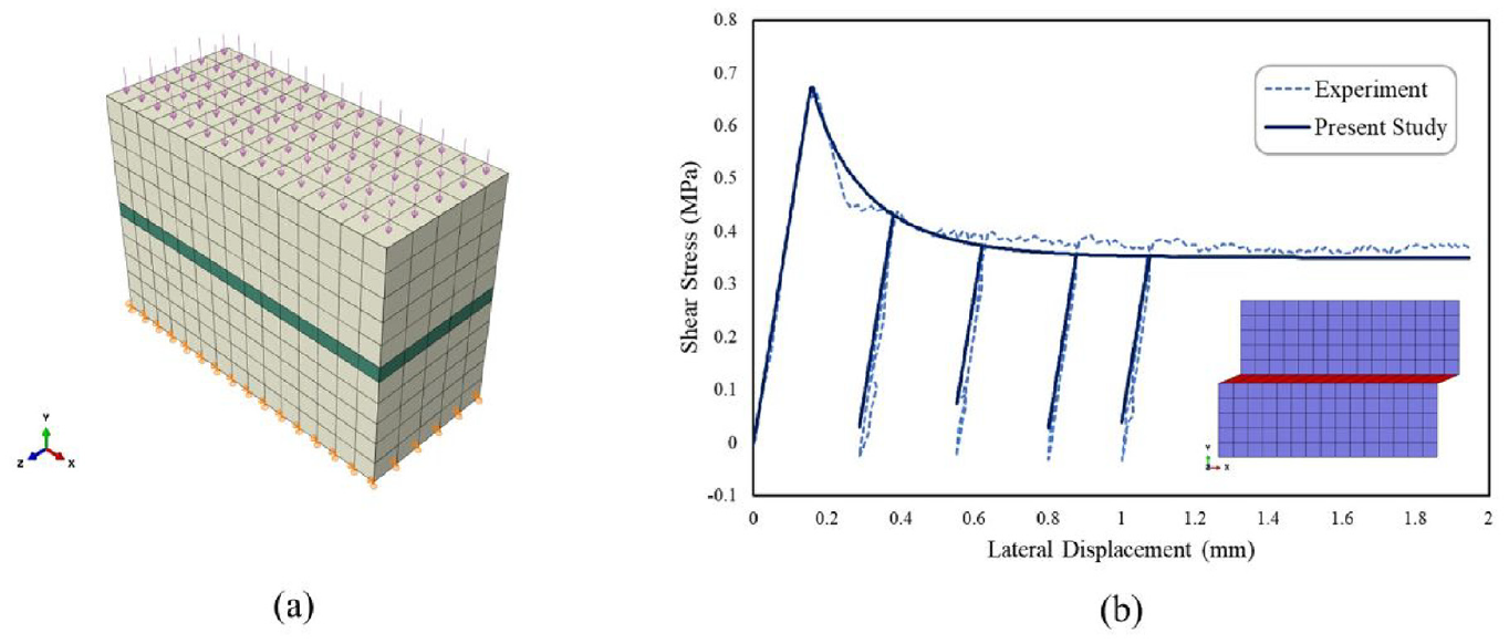
(a) Finite element model for brick couplets. (b) Load-displacement response compared with the experimental results.
The material parameters were again selected based on experimental data provided by Chaimoon [49]. The elastic constants for the brick material were E = 14,500 MPa and υ = 0.06, while the normal and tangential components of the interfacial elastic stiffness were 50.0 and 5.0 MPa/mm, respectively. Furthermore, the interfacial shear strength parameters were co = 0.3 MPa and µo = 0.7, while the tensile strength of the joints was ft = 0.1 MPa. Mode II fracture energy release rate was chosen as
The predicted shear stress vs. lateral displacement characteristic is provided in Figure 5(b), and the results are compared with the experimental data. The figure also shows the deformed finite element mesh. It is evident that both the ultimate and residual shear strengths are in a good agreement with the recorded experimental values. Also, the predicted postpeak deformation, for both an active process and the unloading–reloading cycles, is fairly consistent with the experimentally observed response.
4.3. Cyclic shear test on a masonry couplet
The laboratory experiments simulated here involved cyclic direct shear tests on two rows of bricks arranged in a running bond pattern [50]. Two types of bricks, referred to as “old” and “new,” were used with dimensions of 208 mm × 100 mm × 64 mm and 193 mm × 92 mm × 55 mm, respectively. Thickness of mortar joints used for these two types of bricks was 13 and 7 mm. The precompression stress for the “old” and “new” brick specimens were 0.33 and 1.34 MPa, respectively.
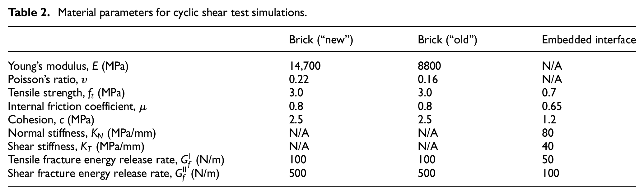
The geometry and the boundary conditions are shown in Figure 6(a). The finite element model employed a total of 1925 elements. The bottom boundary was fixed, and the compressive load was applied at the top of the assembly. This was followed by application of lateral displacement applied in one and a half cycles. The material parameters used for these simulations are summarized in Table 2.
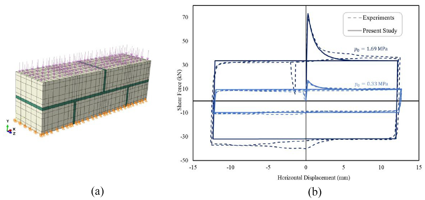
(a) Discretized model of the two-leaf masonry assembly. (b) Load-displacement response for the cyclic shear loading compared with the experimental results for two different normal compressive loads.
Material parameters for cyclic shear test simulations.
The results of the analysis are shown in Figure 6(b). The predicted initial ultimate strength and the strain-softening branch are very close to those recorded in the experiments. Once the residual shear strength is reached, the load-displacement curve follows the same path in both directions of the shear load. Overall, the basic trends, including the dependence of peak and residual shear strength on the value of the compressive stress, are consistent.
4.4. Simulation of a three-point bending test on a masonry beam
This section provides the numerical analysis of a three-point bending test on a masonry beam consisting of four rows of bricks arranged in a running bond pattern. The simulations were carried out on the basis of the experimental results reported by Chaimoon [49]. The masonry beam consisted of bricks measuring 230 mm × 76 mm × 110 mm in size with mortar joint thickness of 10 mm. The total length of the beam was 1430 mm, and the depth was 334 mm.
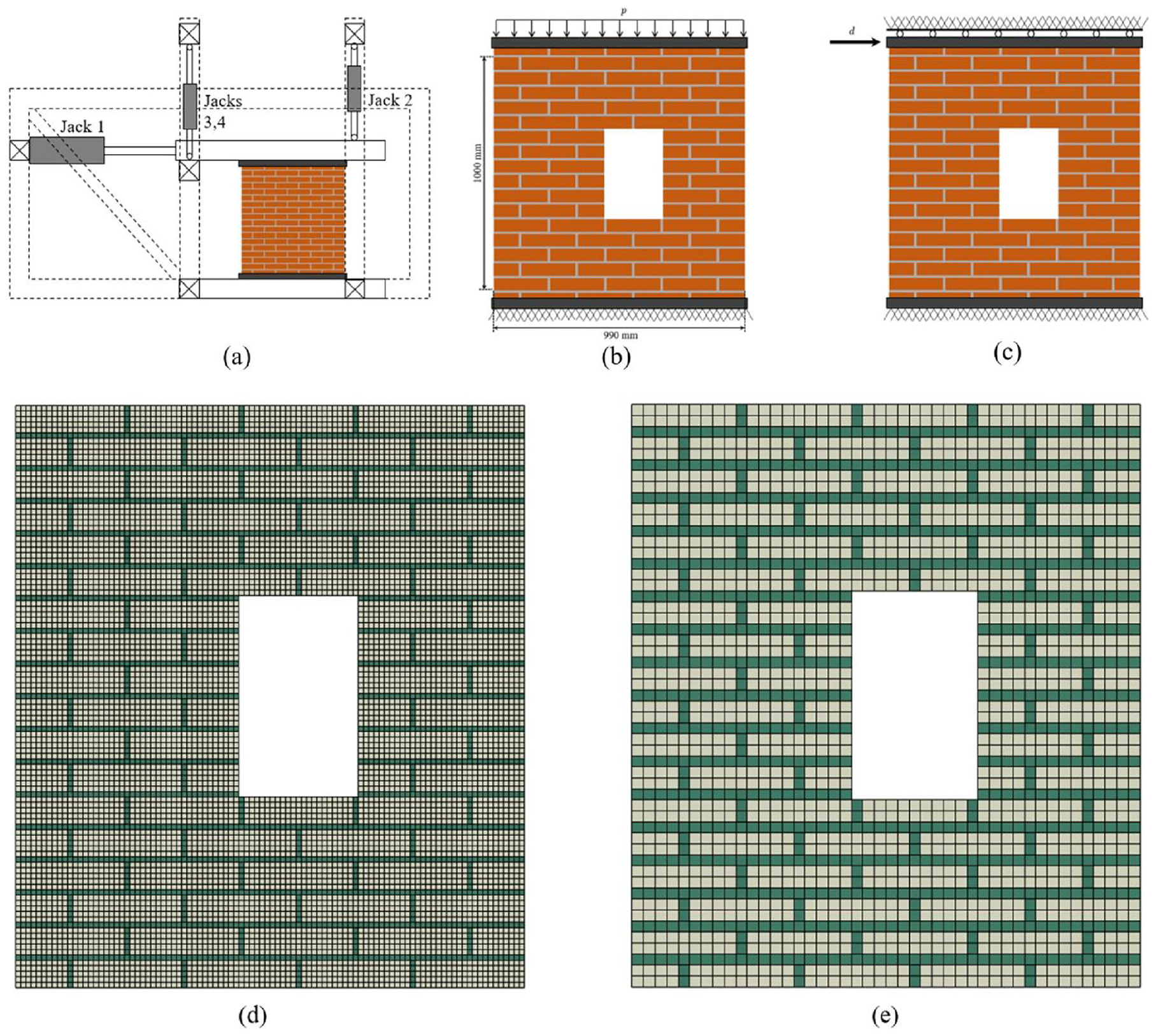
The model was discretized into a total of 11,206 eight-noded cubic elements, as shown in Figure 7(a). One row of nodes in the middle part of the bottom left brick was fixed in the horizontal and vertical directions while the opposing row of nodes, on the right side of the beam, was fixed only in the vertical direction. The displacements were applied incrementally to the two rows of nodes at the top of the brick located in the middle of the beam. The direction of applied displacement was reversed twice during the simulation to model the cyclic loading component of the experiment. The material parameters were again selected based on the information provided in the original reference, and their values are summarized in Table 3.
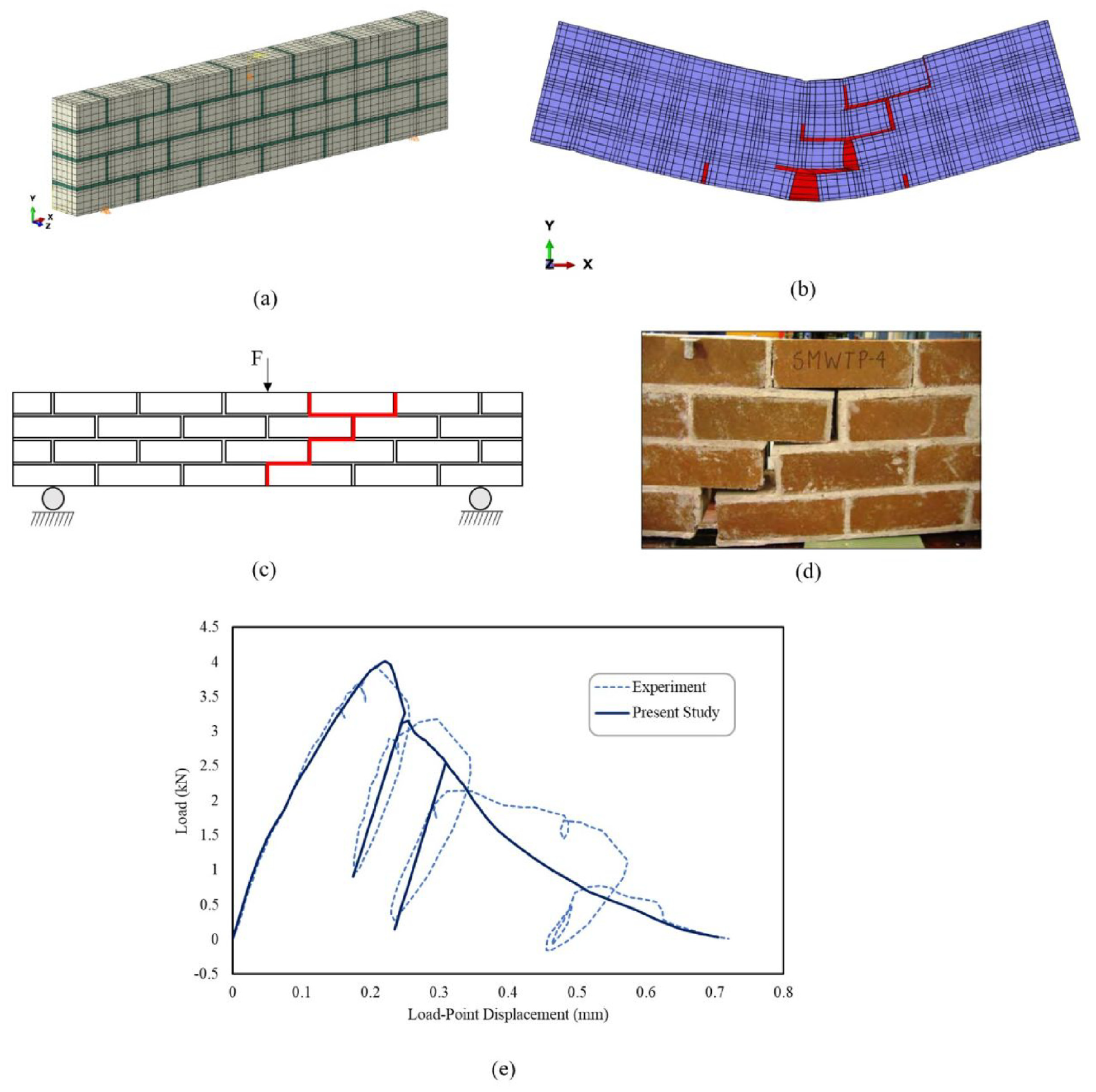
(a) Finite element model of the three-point bending test on masonry beam. (b) Deformed mesh showing the final crack pattern. (c) Schematic illustration of the experimentally observed crack pattern. (d) Picture of the damage pattern. (e) Load-displacement curve compared with experimental data.
Material parameters for three-point bending test simulation.
The main results of analysis are provided in Figure 7. Figure 7(b) shows the deformed mesh and the cracked region at the end of the simulation. The latter is compared with the schematic (Figure 7(c)) and the actual (Figure 7(d)) crack pattern observed in the experiments. The crack mode includes tensile cracking of head joints in the bottom portion of the beam, as well as a combined tensile or compressive shear cracking of bed joints and head joints. To obtain the crack propagation as observed in the experiment, an imperfection was introduced consisting of a minor reduction in the strength parameters of constituents in the right half of the beam. This was required since otherwise the cracks would propagate symmetrically through the beam, as the loading and boundary conditions are both symmetric.
It is evident that the load-displacement response, shown in Figure 7(e), has been predicted quite well. There is a slight reduction in the slope of the curve prior to reaching the ultimate load, which can be attributed to the development of the tensile crack in the head joint located at the bottom of the beam. The postpeak strain-softening response starts to form later as the cracks develop further through the depth of the beam towards the top.
5. Numerical analysis involving tests on masonry walls
5.1. Masonry wall under monotonic shear and compressive load
In this section, the experimental tests on scaled masonry walls are simulated using the proposed simplified approach with interfaces embedded in the adjacent bricks. The first example deals with tests carried out by Raijmakers and Vermeltfoort [51], and Vermeltfoort et al. [52]. The experiments were conducted on walls made of bricks with dimensions of 210 mm × 52 mm × 100 mm and mortar joints with 10 mm thickness. The bricks were arranged in a running bond pattern in 18 rows, with top and bottom rows being confined by the loading platens. The length of the wall was 1000 mm, and its height, excluding the top and bottom rows, was 990 mm.
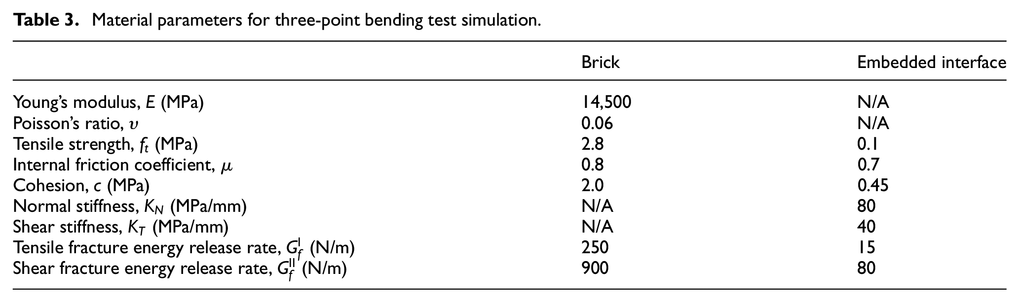
The experiments were carried out on walls with and without an opening. In the first stage, a compressive load of intensity 0.4 (for solid wall) and 0.3 MPa (wall with opening) was applied. After the normal load was in place, a lateral displacement was imposed through the top platen while the vertical displacement was prevented using the vertical loading jacks. Figure 8(a) shows the experimental setup in which the loading frame and actuators induced the boundary conditions for the two steps mentioned earlier (cf. Figure 8(b) and (c)). The roller support shown in Figure 8(c) represents the active vertical loading through jacks 2–4 which prevented vertical movements of the top of the wall during the shear loading.
(a) Schematic diagram of the experimental setup. (b and c) Boundary conditions for the two loading steps. (d and e) Fine and coarse mesh for the FE analysis.
The FE simulations presented in this section were performed using two structured meshes with different size of elements to investigate the mesh sensitivity of the solution incorporating the proposed methodology. The model with a fine mesh consisted of 33,822 eight-noded cubic elements, while the coarser mesh incorporated 8272 elements. Figure 8(d) and (e) shows both models, i.e., with fine and coarse discretization, for the wall with an opening. A similar mesh was used for the solid wall as well. In the analysis, the bottom edge of the walls was fixed, and the normal compressive load was applied to the top boundary. After reaching the desired intensity, the vertical displacement at the top of the wall was constrained while lateral displacement was applied. At this stage, the evolution of shear force was recorded. The simulations were carried out using the material parameters listed in Table 4, which again were selected based on the data provided in the original reference.
Model parameters for simulating walls under shear.
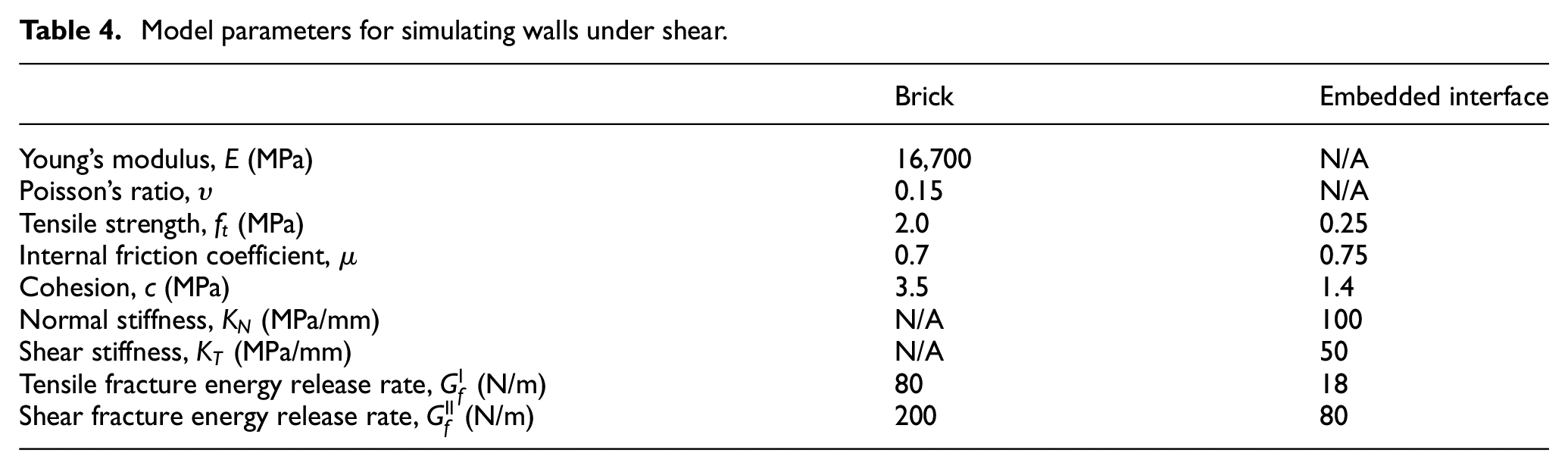
Figure 9(a) shows the load-displacement response for the finite element model of the solid wall with two different mesh sizes. The results are compared with the experimental data. The representative crack pattern observed in the experiment is reproduced in Figure 9(b) and is compared with crack patterns obtained from finite element simulations shown in Figure 9(c) and (d) for fine and coarse mesh, respectively. Figure 10 shows the numerical results for the wall with an opening. Here again, both the load-displacement curves and the fracture mode are compared with the experimental records.
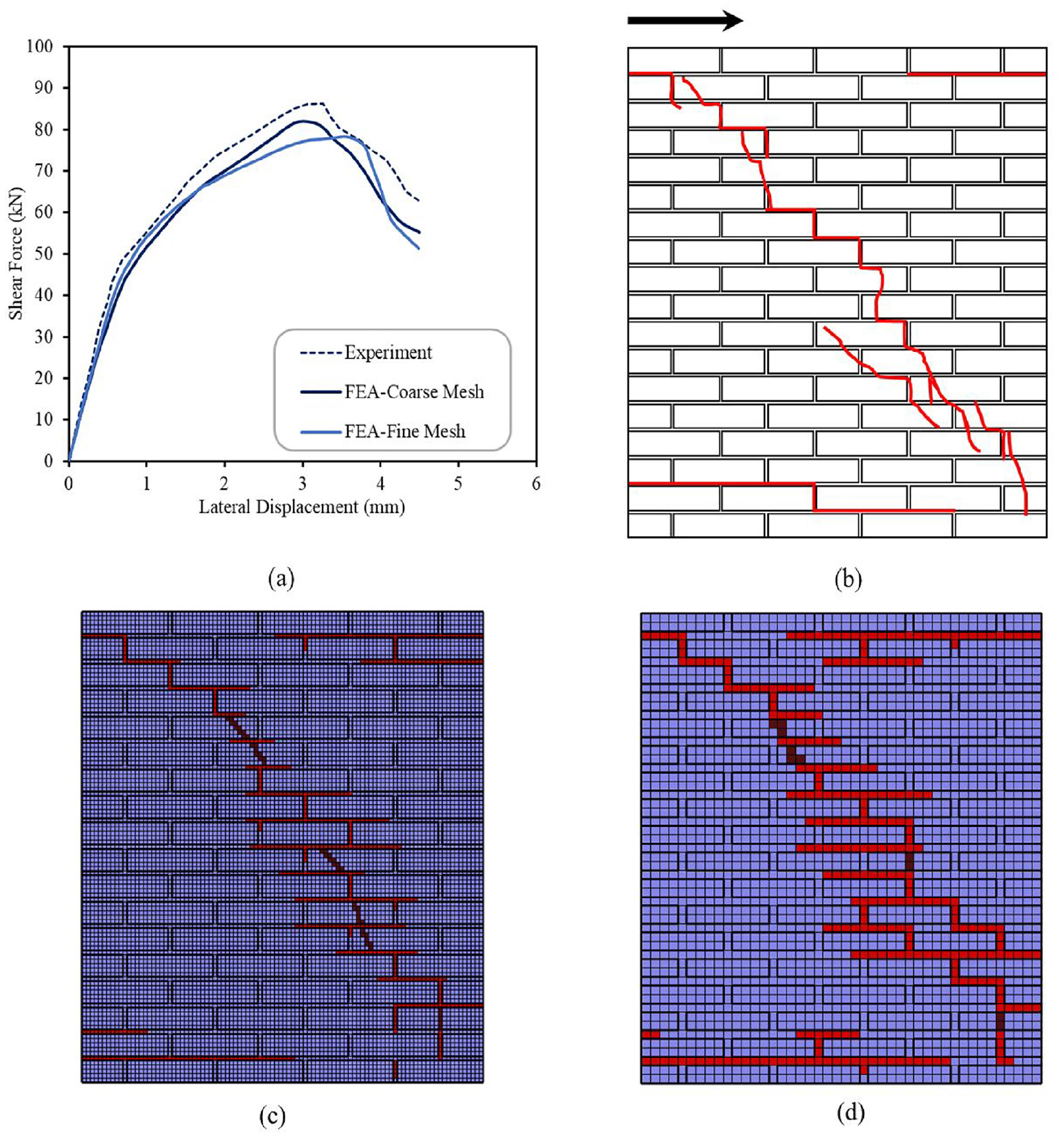
(a) Load-displacement curves compared with the experimental data. (b) Schematics of fracture pattern as reported in experiments. (c and d) Crack pattern obtained using fine and coarse mesh (cracks developed in bricks are shown in darker shade).
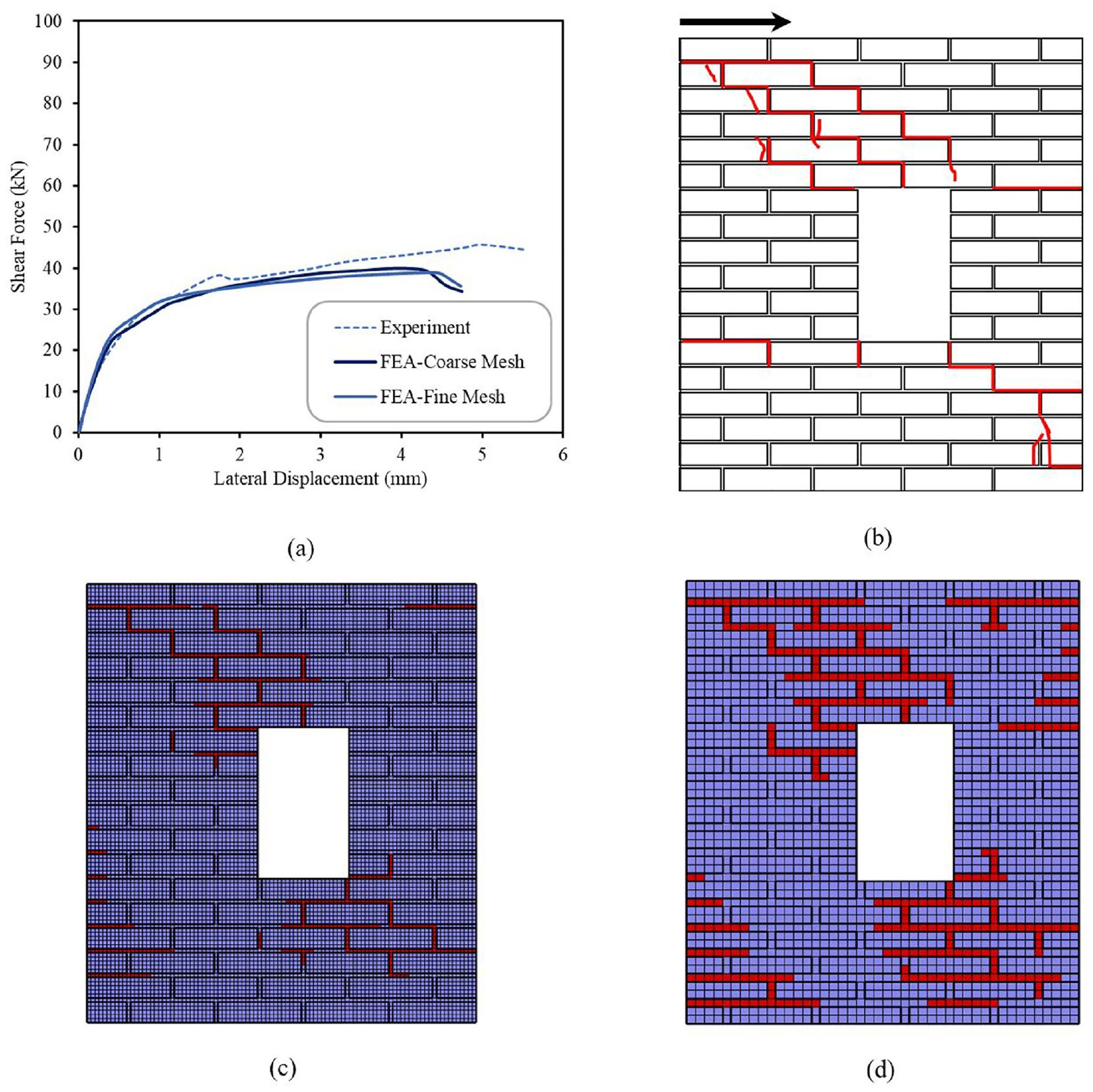
(a) Load-displacement curves compared with the experimental data. (b) Schematics of fracture pattern as reported in experiments. (c and d) Crack pattern obtained using fine and coarse mesh.
The numerical predictions seem to be in agreement with the experimental data in all key factors that include the ultimate bearing capacity and the crack pattern which develops in both the brick–mortar joints and the brick units. For the solid wall, the top right and bottom left sections show tensile horizontal cracks in bed joints. In the rest of the domain, the experimental data show a zig-zag pattern of fracture involving cracking in the bricks and brick–mortar joints. This is particularly evident at the top left and bottom right as well as in the middle part of the wall. The numerical results display a similar trend.
For walls with an opening, the experimental results show more distinguishable zig-zag crack patterns in the top-left and bottom-right corners of the opening that propagate to the corners of the walls. Numerical simulations display a similar effect in terms of the overall orientation of the diagonal macrocracks. Cracking within the bricks takes place near the top-left and bottom-right corners of the walls which is consistent with the experimental observation.
As expected, the ultimate bearing capacity for the walls with opening is significantly smaller compared with the solid walls (cf. Figures 9(a) and 10(a)). The same conclusion applies to the initial stiffness. The mesh size appears to have a negligible effect on the solution, which stems primarily from incorporation of the internal length scale parameter. The models with finer mesh give a slightly lower assessment of the ultimate load while the stiffness degradation that stems from propagation of localized damage is very similar.
5.2. Full-scale masonry wall under shear and compressive load
The last example provided here deals with simulation of tests on unreinforced masonry walls conducted by Korswagen et al. [53]. The experiments were carried out on 3.07 m × 2.70 m × 0.10 m walls that were glued to steel beams at the top and the bottom. Both beams were connected by means of steel columns. The top beam was attached via connections that allowed rotation and horizontal displacement, while the bottom beam was fully fixed to the setup frame. The walls had an opening with an embedded concrete lintel at the top of the free span extending approximately 100 mm on each side. The dimensions of bricks were 210 mm × 50 mm × 100 mm with mortar thickness of 10 mm. The weight of the top beam was reported to induce a uniform compressive stress of 0.12 MPa. The walls were then loaded in shear by applying a horizontal displacement to the top beam.
Figure 11(a) shows the geometry and the finite element discretization of the wall. The mesh incorporated the total of 79,800 eight-noded cubic elements. The boundary nodes at the base of the model were fixed in horizontal and vertical directions, which was consistent with the experimental setup. To simulate the boundary conditions associated with the presence of the top steel beam, the boundary nodes were kinematically tied to a reference point [46] at which the lateral displacement was applied. This ensured that the boundary motion was consistent with the experimental conditions that allowed for the steel beam rotation. The material parameters, which are summarized in Table 5, were chosen in accordance with the information provided by Korswagen et al. [53]. Since the experimental data did not show any crack development in the brick units, the bricks themselves were considered as elastic, with Young’s modulus of 4600 MPa and Poisson’s ratio of 0.14. Moreover, the elastic properties of the concrete lintel at the top of the opening were taken as E = 30 GPa and υ = 0.15.
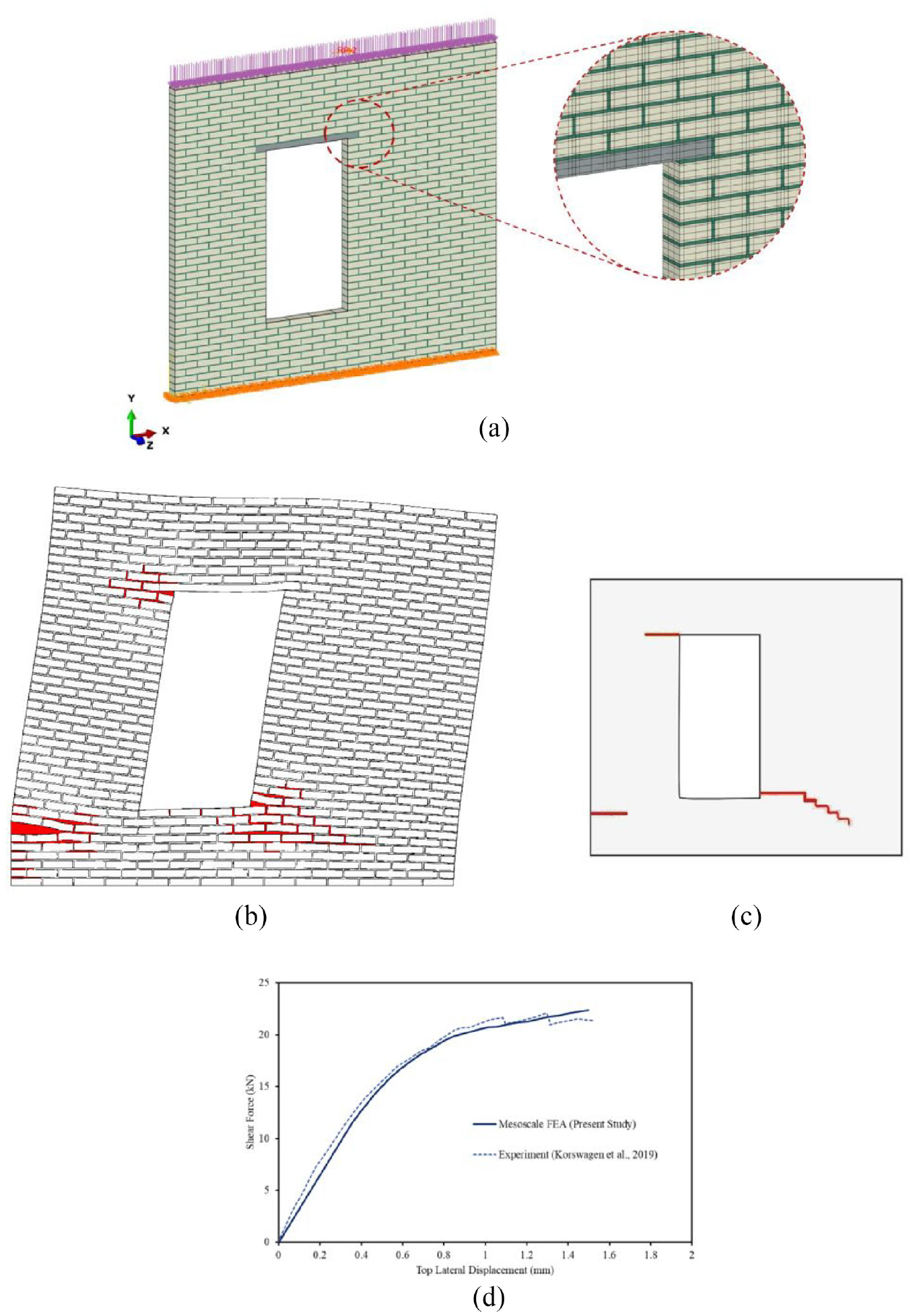
(a) Finite element model with an enlarged portion showing the details of the mesh. (b) Crack pattern from the FE analysis. (c) Schematic illustration of the crack pattern observed at the end of experiment on TUD-Comp 41 specimen. (d) Load-displacement characteristics compared with the experimental data reported in the work by Korswagen et al. [53].
Material parameters used in the finite element simulation of monotonic shear loading of masonry wall.
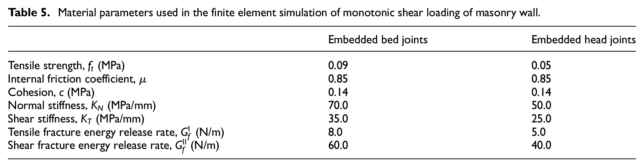
Figure 11(b) shows the deformed finite element model together with the obtained crack pattern. Note that the finite element mesh is not shown here to improve the clarity of the results. The fracture mechanism appears to be in a good agreement with the experimental observation, the latter shown schematically in Figure 11(c). There are three major cracked domains that develop in the bottom left of the wall, as well as the top left and bottom right corners of the opening. The load-displacement curve for the shear stage is shown in Figure 11(d). It is evident that the simplified methodology proposed in this work, in which the presence of joints is accounted for via the CLED, i.e., equations (1) and (2), is fairly accurate in predicting both the fracture pattern the ultimate load and requires less computational effort as the interfaces are explicitly embedded in the adjacent referential volume.
6. Concluding remarks
In this work, the application of the constitutive law with embedded discontinuity for modelling the mechanical response of masonry at mesoscale was extensively studied. Since the interfaces between the brick units and mortar joints generally act as planes of weakness, their presence was accounted for through a homogenization procedure incorporating the volume averaging. This approach is pragmatic and efficient in implementation and adequately captures the complex behaviour of masonry in boundary value problems. Its primary advantage lies in the fact that the same formulation can be used for capturing the fracture propagation in brick units as well. The difference between the crack initiation process in bricks compared with elements with embedded interface, is that the crack orientation in bricks is not known a priori and needs to be identified by means of a suitable criterion.
The proposed approach is practical for analysis of existing small and medium-sized masonry structures since it requires a limited amount of information regarding the mechanical properties of the constituents. The required properties can be obtained from simple laboratory experiments (i.e., tensile and direct shear tests) on small samples acquired from parts of the existing structure.
The numerical implementation of the framework incorporated an implicit integration scheme to attain the stress equilibrium and to assess the embedded crack opening/sliding at the element level. The use of the implicit integration scheme ensures the stability of the analysis and the numerical convergence. The proposed methodology employing embedded interfaces was first verified against a detailed analysis incorporating the mortar joints and the brick–mortar interface elements. It was demonstrated that the level of approximation in the proposed simplified approach does not markedly impair the accuracy and, at the same time, enhances its computational efficiency.
As mentioned earlier, the scope of the numerical study was limited to masonry with running bond arrangement, subjected to in-plane loading. The proposed formulation was validated through simulation of a series of monotonic and cyclic tests on masonry triplets and couplets under tensile and shear loading conditions. The results showed a good agreement with the experimental data published in literature. Later, more complex examples involving masonry walls under in-plane compression and shear were considered, and the results were again compared with those recorded in the experiments.
Various examples given in this study showed that the most frequent mode of fracture involves failure along the brick–mortar interfaces, while for some problems the cracking took place also within the brick units. Cracks in bricks develop mainly in the tensile splitting mode, although in some cases they may also undergo a frictional failure. In general, in a typical masonry layout, the crack propagation process can transfer from bricks towards the brick–mortar interface but is less likely to follow the opposite path. The cracks also form at the junction between the bed and head joints. In this case, the dominant crack direction can be assessed based on the values of the failure function along these two respective orientations.
Footnotes
Declaration of conflicting interests
The author(s) declared no potential conflicts of interest with respect to the research, authorship and/or publication of this article.
Funding
The author(s) disclosed receipt of the following financial support for the research, authorship and/or publication of this article: The research presented here was supported by the Natural Sciences and Engineering Research Council of Canada through a Collaborative Research and Development Grant (CRD) in partnership with Hydro-Quebec.