Motivated by the need for new materials and green energy production and conversion processes, a class of mathematical models for liquid crystal elastomers (LCEs) integrated within a theoretical charge pump electrical circuit is considered. The charge pump harnesses the chemical and mechanical properties of LCEs transitioning from the nematic to isotropic phase when illuminated or heated to generate higher voltage from a lower voltage supplied by a battery. For the material constitutive model, purely elastic and neoclassical-type strain energy densities applicable to a wide range of monodomain nematic elastomers are combined, while elastic and photothermal responses are decoupled to make the investigation analytically tractable. By varying the model parameters of the elastic and neoclassical terms, it is found that LCEs are more effective than rubber when used as dielectric material within a charge pump capacitor.
To end the use of fossil fuels, more materials that enable green energy production and conversion processes are sought and developed [1, 2]. In particular, flexible energy harvesters made of rubber-like materials demonstrate great potential for generating low carbon renewable energy in emerging technologies [3, 4].
This paper considers a liquid crystal elastomer (LCE) incorporated in a theoretical charge pump electrical circuit. Charge pumps are convenient and economical devices that use capacitors to generate higher voltages from a lower voltage supplied by a source battery. The simplest capacitor consists of two parallel plate electrical conductors separated by air or an insulating material known as the dielectric. The plates are connected to two terminals, which can be wired into an electric circuit. When the performance of a capacitor changes by altering the distance between plates or the amount of plate surface area, a variable capacitor is achieved.
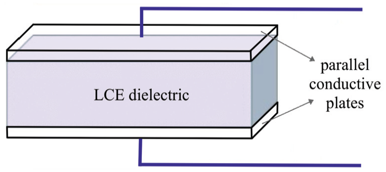
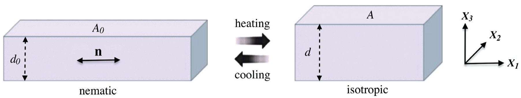
LCEs are top candidates for dielectric material because they are capable of large strain deformations which are reversible and repeatable under natural stimuli like heat and light [5, 6]. This is due to their unique molecular architecture combining the flexibility of polymeric networks with liquid crystal self-organisation [7]. In Figure 1, a capacitor with LCE dielectric between two compliant electrodes is presented schematically. Figure 2 depicts the LCE nematic–isotropic phase transition under thermal stimuli. Light-induced shape changes for LCEs containing photoisomerising dye molecules can be represented in a similar manner.
Schematic of parallel plate capacitor with LCE dielectric between two compliant electrodes.
Reversible natural deformation of LCE dielectric under nematic–isotropic phase transition caused by temperature variation. The thickness and surface area of the LCE change, while the volume is preserved, i.e., . In the nematic phase, the director for liquid crystal orientation is aligned in the first Cartesian direction, parallel to the surface, while in the isotropic phase, liquid crystal molecules are randomly oriented.
A hypothetical charge pump which converts solar heat into DC electricity was proposed in Hiscock et al. [8]. In that study, the LCE was described by the neoclassical model [9–11] and elastic and thermal responses were decoupled to make the theoretical model analytically tractable.
In this paper, purely elastic and neoclassical-type strain-energy densities are combined. The resulting composite model is applicable to a wide range of nematic elastomers and can be reduced to either the neo-Hookean model for rubber [12] or the neoclassical model for ideal LCEs. As in Hiscock et al. [8], the elastic deformation and photothermal responses are decoupled. Then, if heat or light is absorbed, the equilibrium uniaxial order parameter can be determined by minimising the Landau–de Gennes approximation of the nematic energy density [7] or a Maier–Saupe mean field model function [13–16], respectively. By varying the model parameters of the elastic and neoclassical terms, it is found that LCEs can be more effective than rubber when used as dielectric material within a charge pump capacitor. Moreover, if the LCE is pre-stretched perpendicular to the director and instabilities such as shear striping or wrinkling are avoided, then the capacitor becomes more efficient in raising the voltage supplied by the source battery.
2. The charge pump circuit
The electrical energy potential stored by a capacitor, known as capacitance, is equal to , where is the magnitude of the charge stored when the voltage across the capacitor is equal to and is measured in farads (F). Capacitance depends on both the geometry and the materials that the capacitor is made of.
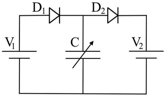
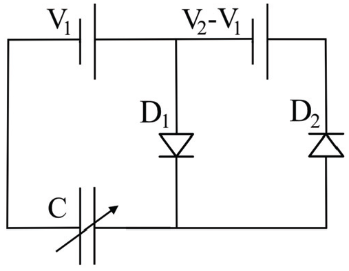
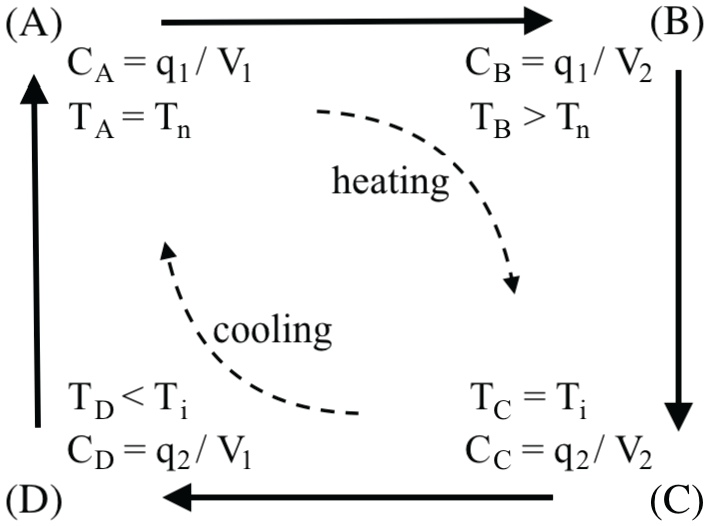
Figure 3 represents schematically a charge pump electrical circuit where the voltage supplied by an external source (battery) is raised to voltage using a variable capacitor with capacitance . The diodes prevent backflow of charge and act as voltage-activated switches. The alternative circuit illustrated in Figure 4 allows for the supply battery to be recharged. Figure 5 shows the operating cycle of a variable capacitor with LCE dielectric containing the following states [8]:
The LCE is at the lowest temperature corresponding to the nematic state, , the input voltage from a supply battery is , and the capacitor is charged to the initial charge . At this state, the capacitance is equal to .
The temperature rises to , so the capacitance decreases to , while the charge remains equal to . Thus, the voltage across the capacitor increases to .
The temperature continues to increase to the isotropic state, , hence the capacitance further decreases to , but the voltage remains equal to , so the charge decreases to .
The temperature drops to , while the charge remains equal to and the capacitance increases to . Upon further cooling to the initial temperature , the battery with voltage charges the capacitor to the initial charge state and the cycle can be repeated.
Charge pump electrical circuit with a single-cell supply battery of lower voltage and a variable capacitor with capacitance that attains a higher voltage [8].
Charge pump electrical circuit with a single-cell supply battery of lower voltage and a variable capacitor with capacitance that attains a higher voltage and recharges the supply battery [8].
Operating cycle of variable capacitor with the dielectric made of LCE generating a higher voltage from a lower voltage [8].
In the above notation and throughout this paper, indices “” and “” indicate a nematic or isotropic phase, respectively.
During one cycle, the external source provides an electrical energy and produces . Thus, the net output generated by this cycle is equal to:
By defining the capacitance ratio:
the maximum generated output per cycle is equal to:
This is attained when:
or equivalently, when:
For the LCE transitioning from a nematic to an isotropic phase and vice versa, changes in light instead of temperature can be used as well.
3. The LCE strain-energy function
To describe the incompressible nematic LCE, the following form of the elastic strain-energy density function is assumed [17–23]:
where denotes the deformation gradient from the reference cross-linking state, such that , while is a unit vector for the localised direction of uniaxial nematic alignment in the present configuration and is termed “the director.” The first term on the right-hand side of equation (6) represents the strain-energy density associated with the overall macroscopic deformation, and the second term is the strain-energy density of the polymer microstructure. In the second term, and denote the natural (or spontaneous) deformation tensor in the reference and current configuration, respectively [6, 24].
Assuming the LCE to be intrinsically uniaxial, the natural deformation tensor takes the form:
where is the identity tensor and:
denotes the natural shape parameter, with representing the scalar uniaxial order of the liquid crystal mesogens ( corresponds to perfect nematic order, while is for the case when the mesogens are randomly oriented). In the reference configuration, is replaced by , with , , and instead of , , and , respectively. Setting , the natural deformation tensors take the form:
The components of phenomenological model given by equation (6) are defined as follows:
where is a constant independent of the deformation, and are the eigenvalues of the tensor , such that , and:
where is a constant independent of the deformation, and are the eigenvalues of the elastic Cauchy–Green tensor , with the local elastic deformation tensor , such that . Note that these components are derived from the classical neo-Hookean model for rubber [12].
The composite model defined by equation (6) thus takes the form:
and has the shear modulus in the infinitesimal strain equal to . This strain-energy function reduces to the neoclassical model for LCEs when [9–11] and to the neo-Hookean model for rubber when [12].
3.1. Photothermal responses
If azobenzene mesogens are embedded in the nematic elastomeric network, then, when photons are absorbed, the so-called Weigert effect [25, 26] occurs where the dye molecules change from straight trans- to bent cis-isomers, causing a reduction in the nematic order. To account for photothermal deformation of a dielectric LCE, we adopt the following modified Maier–Saupe mean field model [13–16]:
where and are defined as before, , with being the total number of mesogens per unit volume and being the temperature per unit of energy, represents the average interaction between two mesogens in the unit of energy, and denotes the fractional number of cis molecules:
If the light is polarised and denotes the angle between nematic director and the light polarisation, then:
where is the fraction of photoactive mesogens, and is the non-dimensional homogeneous light intensity.
If the light is unpolarised and is the angle between nematic director and the light beam direction, then:
The expressions for the functions and are, respectively:
and
In the absence of light, and the energy function defined by equation (13) reduces to:
The ratio between photoactive and non-photoactive mesogens can also be taken into account [14, 15, 27].
4. Energy conversion
At state (A), the LCE dielectric is considered either in its natural configuration or pre-stretched perpendicular or parallel to the nematic director, so that the surface area is increased and the distance between plates is reduced, hence the initial capacitance increases. In all cases, the LCE can be actuated by illumination or heating.
Assuming , the energy functions and described by equations (12) and (13), respectively, can be treated separately, and the equilibrium scalar order parameter obtained by minimising the function . Experimental results on photothermal shape changes in LCEs are reported in Finkelmann et al. [28], Guo et al. [29], and Yu et al. [30]. In Goriely et al. [27], a general theoretical model for photomechanical responses in nematic–elastic rods is presented. Photoactive LCE beams under illumination are modelled in Norouzikudiani et al. [31]. Reviews of various light-induced mechanical effects can be found in Ambulo et al. [32], McCracken et al. [33], Warner [34], and Wen et al. [35].
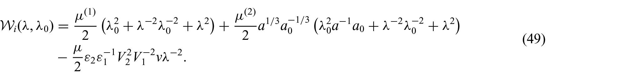
Similarly, when heat instead of light is absorbed [8], the uniaxial order parameter can be determined by minimising the following Landau–de Gennes approximation of the nematic energy density:
where , and are the material constants, with depending on temperature [6]. For nematic LCEs, the contribution of the above function to the total strain-energy density including both the isotropic elastic energy and the nematic energy functions was originally analysed in Finkelmann et al. [24] and more recently in Mihai et al. [36].
4.1. Natural deformation
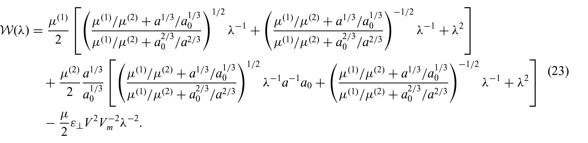
When the LCE is in its natural configuration at state (A), as the capacitor is connected to the source battery, the total energy function of the system takes the following form (see also Hiscock et al. [8]):
where the last term represents the electrical energy per unit volume. Here, is the volume of the dielectric, with being the surface area and being the distance between the conductive plates, is the voltage across the capacitor, and is the capacitance given by:
where is the permittivity for the perfectly nematic phase, and is the relative permittivity when the director is perpendicular to the electric field. The “⊥” notation stands for the electric field being applied perpendicular to the nematic director.
We denote by the voltage where the total energy is comparable to the stored elastic energy, such that:
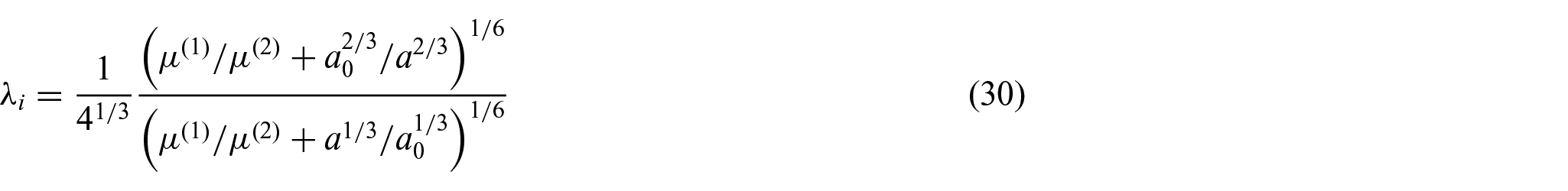
Minimising the total energy function described by equation (20) with respect to gives:
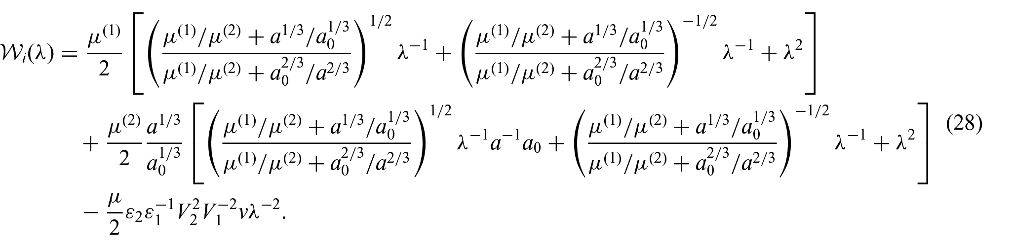
At the initial state (A), where the LCE exhibits nematic alignment, there is no light, i.e., , and minimising the energy function defined by equation (18) with respect to yields the optimal value . Similarly, at this state, and , hence the function given by equation (23) becomes:
where:
denotes the operating voltage. By solving for and , the following system of equations:
we obtain:
At state (C), where , as light intensity increases so that phase transition to the isotropic state is induced, the order parameter reduces and capacitance decreases. Then, the total energy function takes the form:
Solving for and , the following system of equations:
then yields:
and
From equations (2) and (21), we derive the capacitance ratio:
4.2. The effect of pre-stretching perpendicular to the director
Next, we consider the LCE dielectric to be pre-stretched in the second direction, i.e., perpendicular to the director, at state (A), with a prescribed stretch ratio [8, 37–39]. As pre-stretching increases the area of the dielectric and reduces the distance between plates, the amount of charge that can be taken from the battery increases. However, two types of instability may occur in this case, namely, shear striping or wrinkling [37, 38]. The formation of shear stripes caused by director rotation in elongated nematic LCEs is well understood [40–47] and has been modelled extensively [17–20, 22, 23, 42, 48–53]. Wrinkling in compressed LCEs was examined theoretically in the literature [51, 54, 55]. In pre-stretched LCEs, wrinkles can form if the voltage is too high, due to the so-called electrostrictive effect observed when charging the electrodes. In this case, the applied Maxwell stress causes contraction in the field direction and elongation in the perpendicular directions. Here, we assume that the input voltage is below but close to the critical magnitude causing wrinkling, and that any reorientation of the nematic director that might occur is reverted (see also Appendix 1).
At the state (A), where and , the energy function given by equation (23) becomes:
Solving for , the equation:
yields:
In addition, solving for , the following system of equations:
produces the wrinkling voltage:
Note that wrinkling occurs when the stress in the second (pre-stretched) direction becomes zero, i.e., .
At state (C), where , the energy function is:
Solving for , the equation:
gives:
Then solving for , the system of equations:
provides the wrinkling voltage:
Similarly, in this case, wrinkling is attained when the stress in the second direction is equal to zero, i.e., .
which is a nonlinear function of the pre-stretch ratio and the capacitance ratio .
4.3. The effect of pre-stretching parallel to the director
We also consider the case when the LCE is pre-stretched parallel to the nematic director at state (A), with a prescribed stretch ratio . In this case, at the state (A), where and , the energy function given by equation (23) becomes:
As before, solving for , the equation:
gives:
Then solving for , the following system of equations:
yields the same wrinkling voltage as in equation (38).
At state (C), where , the energy function is equal to:
Then solving for , the equation:
gives:
Since the LCE tends to contract in the pre-stretched direction while expanding in the thickness direction, there is no wrinkling.
In this section, we present a set of numerical results to illustrate the performance of the theoretical model for the LCE-based charge pump. Following Hiscock et al. [8], we choose the shear modulus and initial thickness for the LCE, and the dielectric constants and . However, here, and the ratio can vary:
When heat is absorbed, we take the scalar uniaxial order parameters and , corresponding to the nematic and isotropic states, respectively [8].
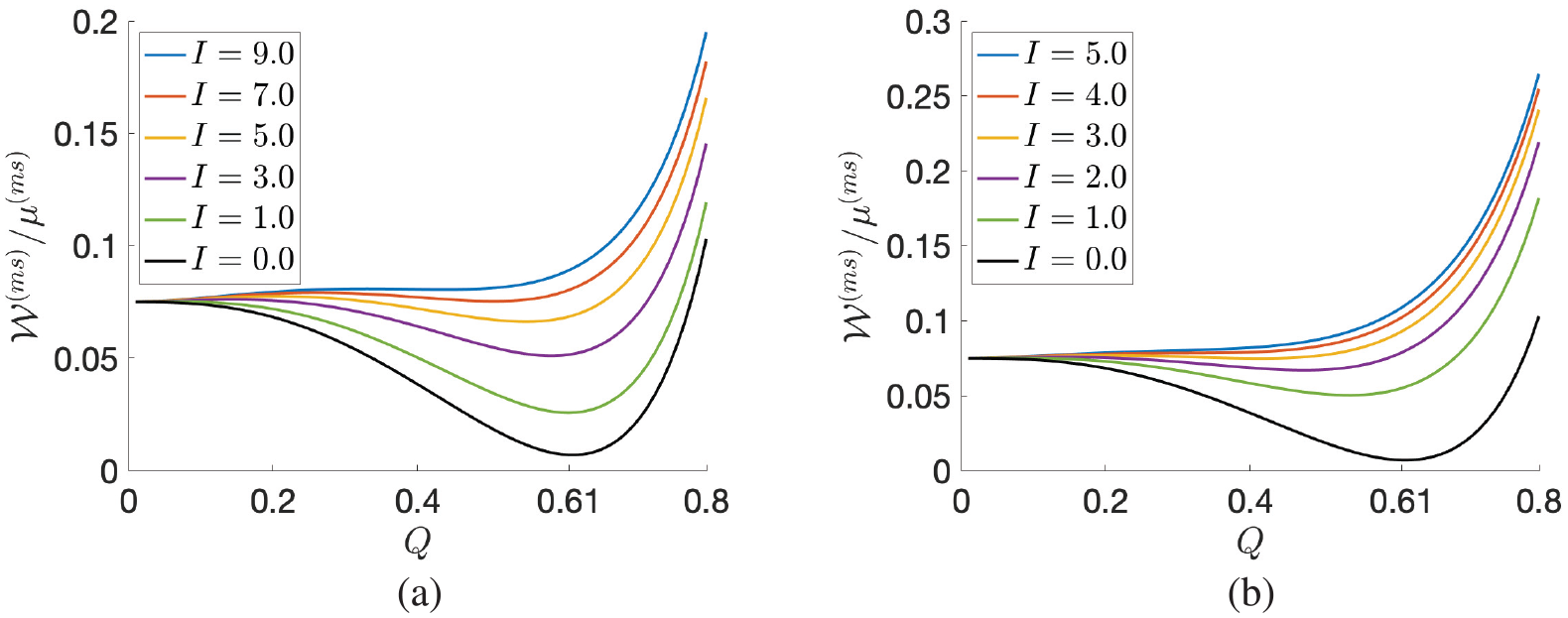
When light is absorbed, we set , , , and [13–15]. At the initial state where there is no light, and the optimal order parameter is , while at the isotropic state, (see Figure 6).
The modified Maier–Saupe mean field energy given by equation (13) as a function of the order parameter when there is no light or the light is: (a) polarised or (b) unpolarised, with varying intensity and , , . As increases, there is a transition from the nematic phase to the isotropic phase. This transition occurs at higher values of when the light is polarised than when it is unpolarised. When , the minimum energy is attained for .
The following parameters can then be calculated directly: and , where .
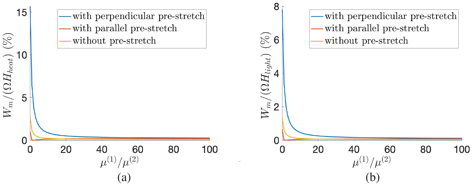
When light is absorbed, the required (solar) input, so that the LCE transitions from the nematic to the isotropic state, is assumed [8], while when the LCE absorbs heat, the energy needed is considered [6, section 2.3]. Then, the efficiency of the system is given by the ratio between the generated output per cycle and the required input. For the three cases where the elastomer is not pre-stretched and when it is pre-stretched either perpendicular or parallel to the nematic director, this is summarised in Figure 7.
The efficiency bound as a function of the parameter ratio for the LCE dielectric absorbing: (a) heat or (b) light when there is no initial pre-stretch or when there is a pre-stretch either perpendicular or parallel to the nematic director, with ratio .
5.1. Energy efficiency under natural deformation
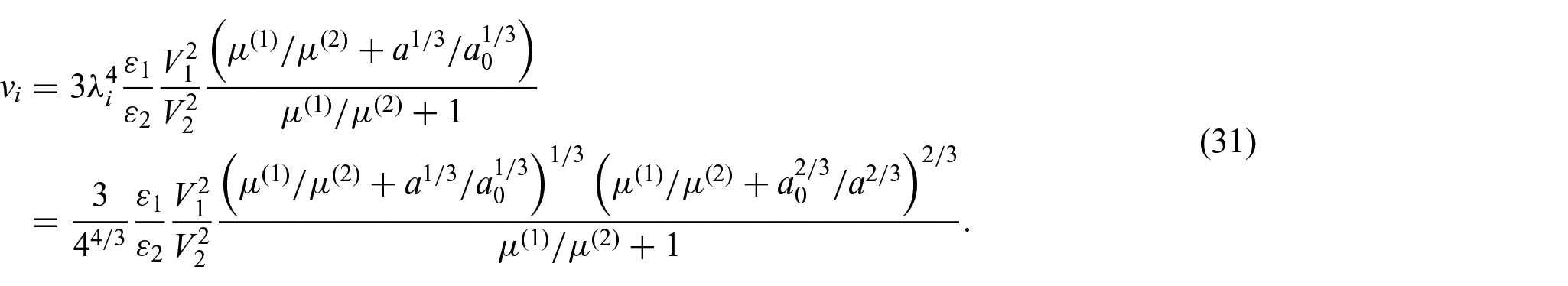
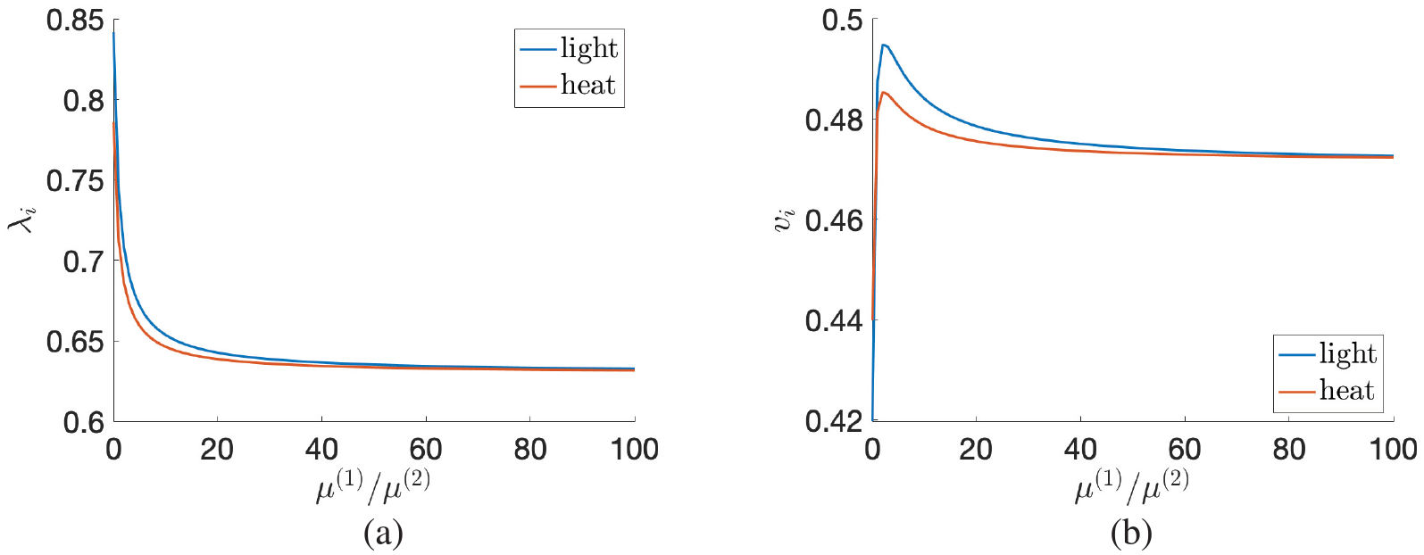
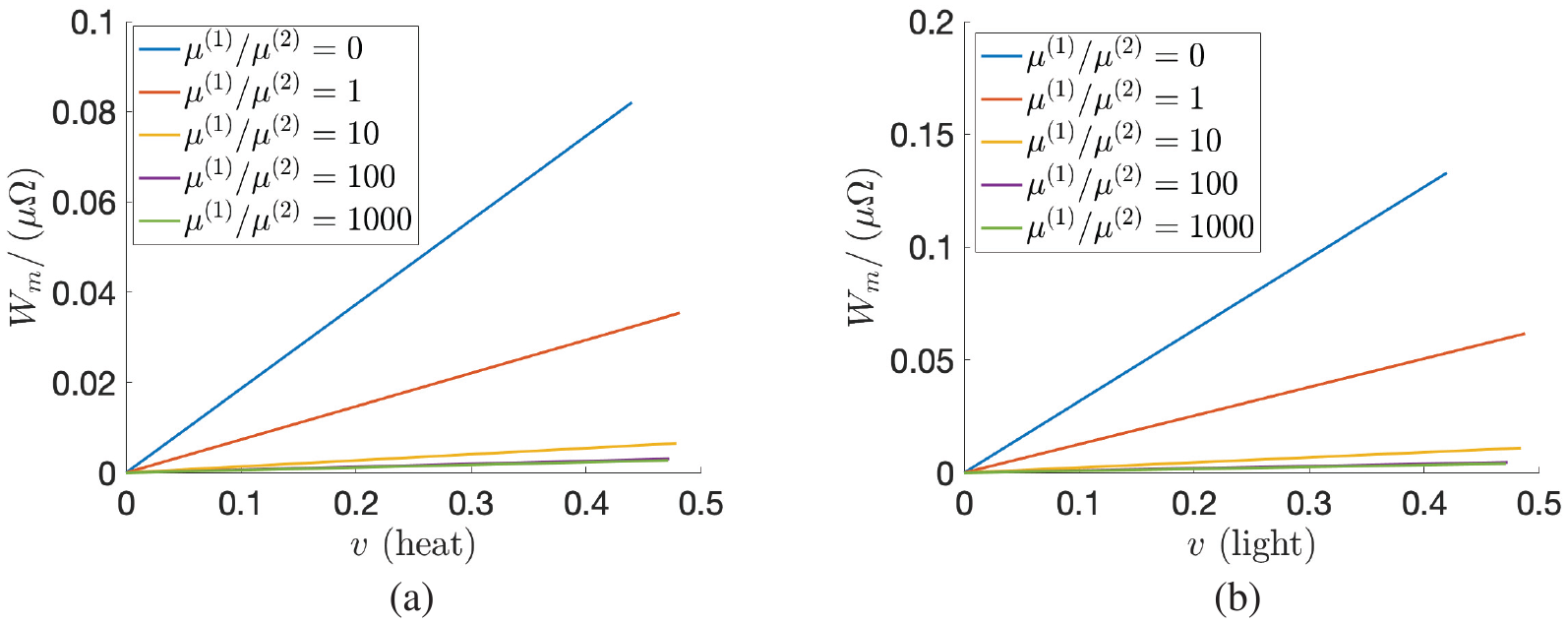
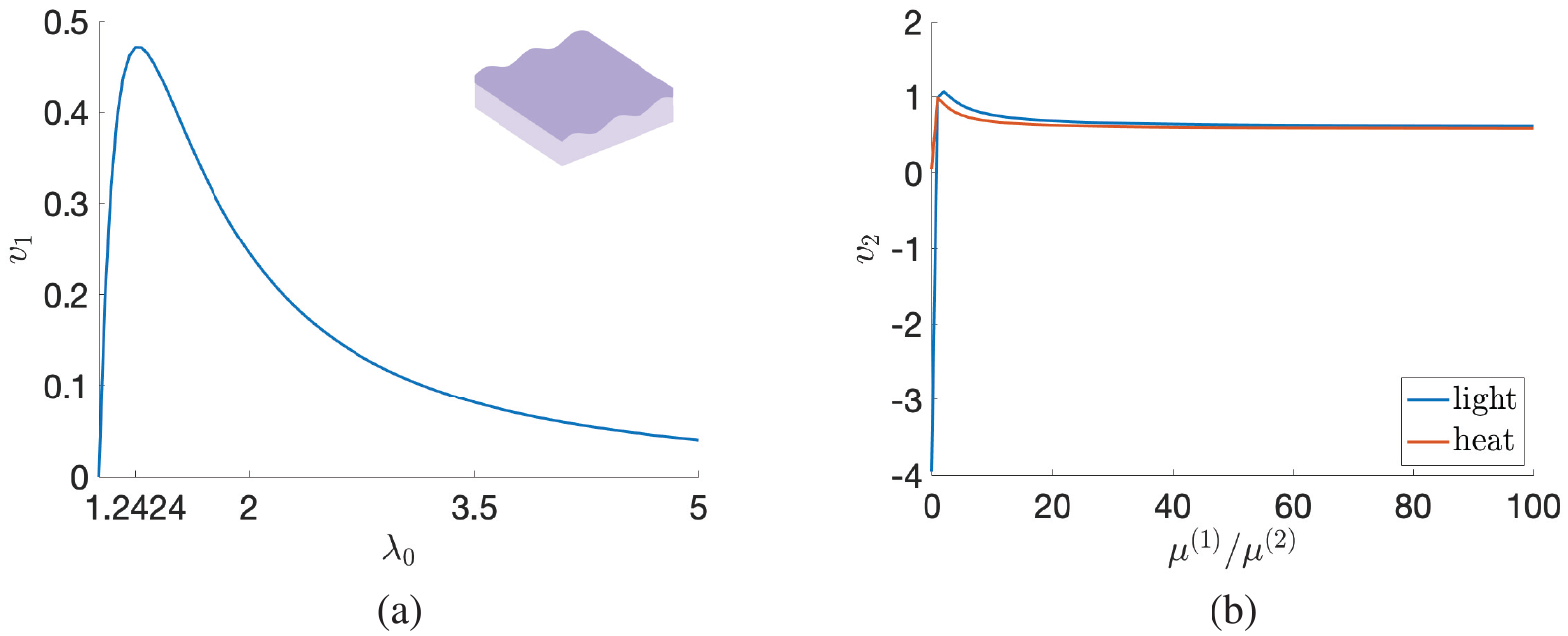
If the LCE is in its natural configuration at initial state (A), then , , and , while at state (C), , , and . The stretch ratio and the corresponding operating voltage , defined by equations (30) and (31), respectively, are plotted as functions of the parameter ratio in Figure 8. By varying this ratio, the maximum optimal output per unit volume is shown in Figure 9. For example, if , then:
When the LCE absorbs heat, the maximum optimal output is equal to per cycle. The efficiency is . The operating voltages are and (see also Appendix 2).
When the LCE absorbs light, the maximum optimal output is per cycle and the efficiency is . The operating voltages are kV and .
(a) The stretch ratio given by equation (30) and (b) the voltage satisfying equation (31) as functions of the parameter ratio for the LCE dielectric absorbing heat or light.
The scaled optimal generated output for when the LCE dielectric absorbs: (a) heat or (b) light.
For these two cases, Figure 7 shows that efficiency decreases as increases. Since corresponds to the neoclassical model for ideal LCEs, while corresponds to the neo-Hookean model for rubber, this figure suggests that LCEs are more efficient than rubber in generating electricity.
5.2. Energy efficiency when pre-stretching perpendicular to the director
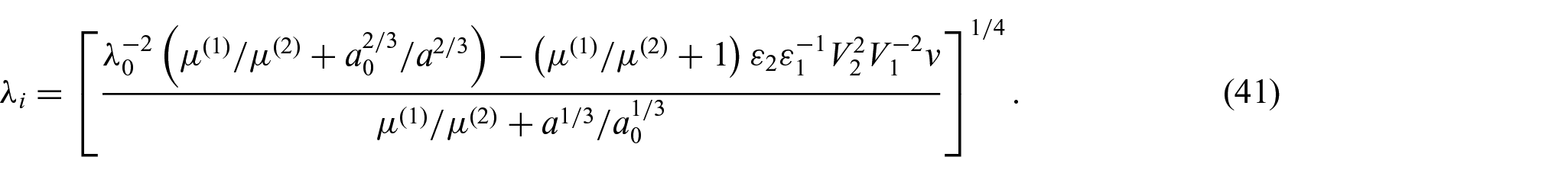
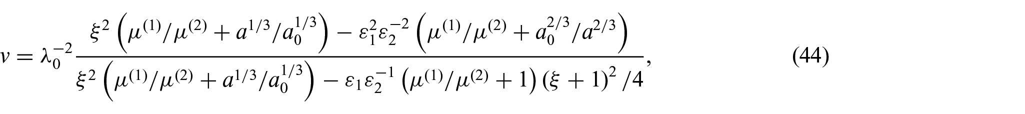
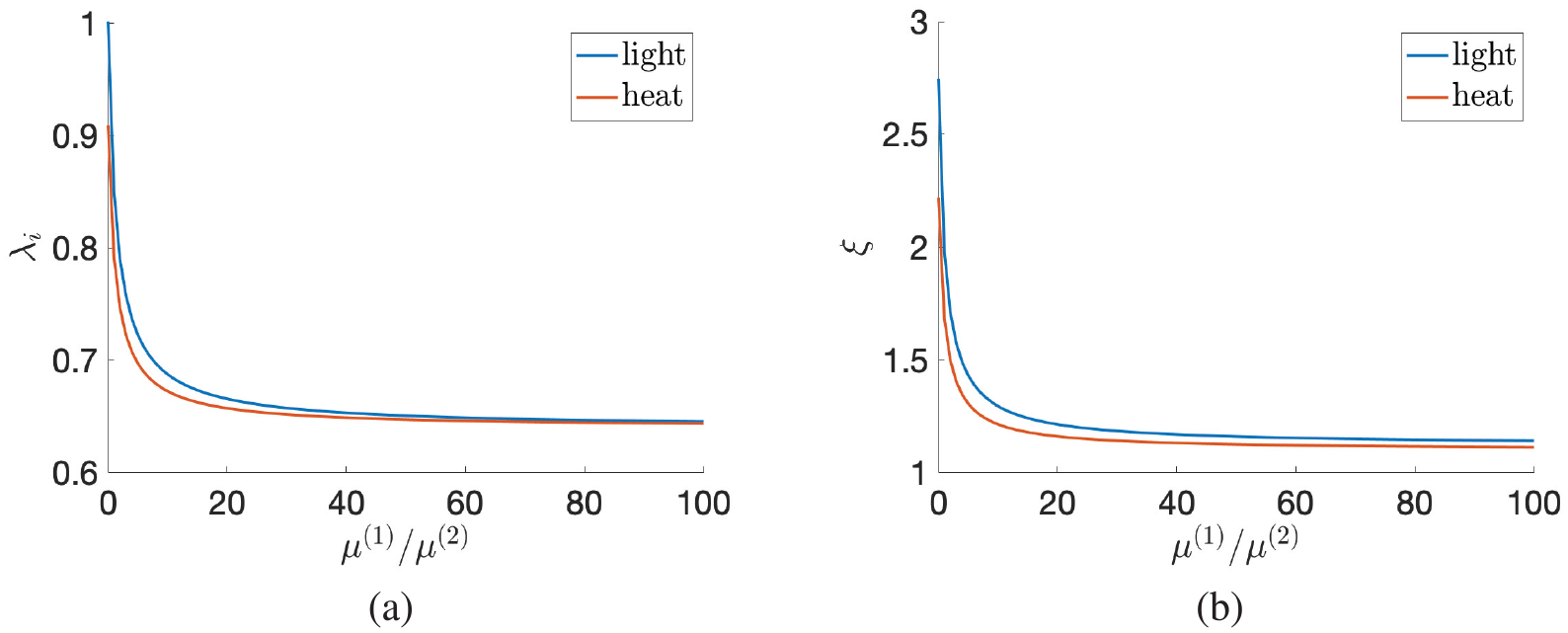
When, at state (A), the LCE dielectric is pre-stretched perpendicular to the director, with initial stretch ratio , the input wrinkling voltage, given by equation (38), is independent of and attains its maximum for , while the output wrinkling voltage, given by equation (43), decreases as the parameter ratio increases. The input wrinkling voltage is plotted in Figure 10(a). To maximise the operating voltage, we choose an input close to the corresponding wrinkling voltage. For example, when and , if the parameter ratio varies, then the output wrinkling voltage given by equation (43) is displayed in Figure 10(b), and the stretch ratio given by equation (41) and capacitance ratio satisfying equation (44) are plotted in Figure 11. In this case, Figure 7 suggests that efficiency decreases as increases. In particular, if , then:
When the LCE absorbs heat, the maximum optimal output is equal to per cycle. The efficiency is . The operating voltages are and .
When the LCE absorbs light, the maximum optimal output is per cycle. The efficiency is . The operating voltages are and .
Wrinkling (a) input voltage given by equation (38) as a function of the pre-stretch ratio and (b) output voltage given by equation (43) as a function of the parameter ratio when the LCE dielectric is pre-stretched perpendicular to the director with ratio and absorbs heat or light. The maximum input wrinkling voltage is attained for .
(a) The stretch ratio given by equation (41) and (b) the capacitance ratio satisfying equation (44) as functions of the parameter ratio when the LCE dielectric is pre-stretched perpendicular to the director with ratio and absorbs heat or light.
For the numerical values of the given parameters, the auxiliary results presented in Appendix 1 imply that director rotation can be ignored when the LCE dielectric is pre-stretched perpendicular to the director.
5.3. Energy efficiency when pre-stretching parallel to the director
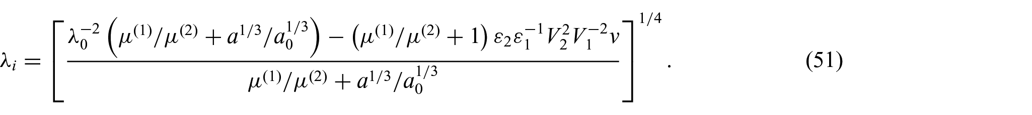
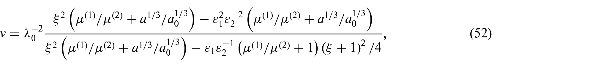
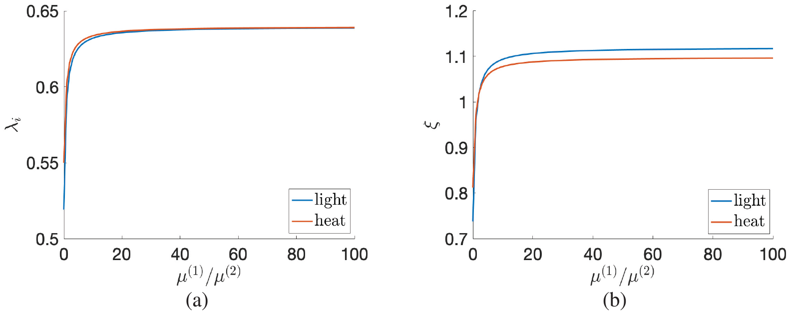
When the LCE dielectric is pre-stretched parallel to the director, the input wrinkling voltage is the same as that shown in Figure 10(a). Choosing again and , when the parameter ratio varies, the stretch ratio given by equation (51) and capacitance ratio satisfying equation (52) are represented in Figure 12. We note that for when the LCE is heated and for when the LCE is illuminated. In this case, the efficiency shown in Figure 7 increases with .
(a) The stretch ratio given by equation (51) and (b) the capacitance ratio satisfying equation (52) as functions of the parameter ratio when the LCE dielectric is pre-stretched parallel to the director with ratio and absorbs heat or light.
6. Conclusion
In this study, a theoretical model is developed for a charge pump with a parallel plate capacitor where the dielectric is made of LCE material that naturally responds to environmental changes such as heat or light. Specifically, heating or illuminating the LCE induces a transition from a nematic to an isotropic state. In addition, the geometry of the dielectric changes and the contact area with the conducting plates and the distance between them are altered. In the charge pump electrical circuit, at the beginning of a reversible cycle of heating and cooling or illumination and absence of light, first the dielectric is assumed to be in a relaxed natural state, then it is pre-stretched so that the capacitance increases by increasing the contact area with the plates and decreasing the distance between them. The LCE is described by a composite strain-energy function which, when taking its constitutive parameters to their limiting values, can be reduced to either the purely elastic neo-Hookean model or the neoclassical model for ideal nematic elastomers. From the above analysis, we infer that (1) LCE is more efficient than rubber when used as dielectric in a parallel plate capacitor and (2) when the dielectric is pre-stretched perpendicular to the director at the initial state of the proposed cycle, the capacitor becomes more effective in raising the voltage supplied by the source battery.
To make these results analytically tractable, in the proposed model, the coupling between elastic deformation and photothermal responses was neglected. This coupling can also be included for more accuracy. When light is absorbed, a more sophisticated model can further take into account the ratio between photoactive and non-photoactive mesogens. Other geometries can be considered as well. Extensive experimental testing should be performed to help establish the best modelling approach.
Footnotes
Appendix 1
Appendix 2
Acknowledgements
The author thanks Professor Peter Palffy-Muhoray (Advanced Materials and Liquid Crystal Institute, Kent State University, Ohio, USA) for useful and stimulating discussions.
Funding
The author(s) received no financial support for the research, authorship, and/or publication of this article.
ORCID iD
L Angela Mihai
References
1.
GalloASimões MoreiraJCostaH, et al. Energy storage in the energy transition context: a technology review. Renew Sust Energ Rev2016; 65: 800–822.
KakichashviliS.Method for phase polarization recording of holograms. Sov J Quantum Electron1974; 4(6): 795–798.
27.
GorielyAMoultonDMihaiL.A rod theory for liquid crystalline elastomers. J Elast2023; 153: 509–532.
28.
FinkelmannHNishikawaEPereitaG, et al. A new opto-mechanical effect in solids. Phys Rev Lett2001; 87(1): 015501.
29.
GuoTSvanidzeAZhengX, et al. Regimes in the response of photomechanical materials. Appl Sci2022; 12: 7723.
30.
YuYNakanoMIkedaT.Directed bending of a polymer film by light. Nature2003; 425: 145.
31.
NorouzikudianiRLucantonioADeSimoneA.Equilibrium and transient response of photo-actuated liquid crystal elastomer beams. Mech Res Comm2023; 131: 104126.
32.
AmbuloCTasminSWangS, et al. Processing advances in liquid crystal elastomers provide a path to biomedical applications. J Appl Phys2020; 128: 140901.
33.
McCrackenJDonovanBWhiteT.Materials as machines. Adv Mater2020; 32: 1906564.
34.
WarnerM.Topographic mechanics and applications of liquid crystalline solids. Annu Rev Condens Matter Phys2020; 11: 125–145.
35.
WenZYangKRaquezJ.A review on liquid crystal polymers in free-standing reversible shape memory materials. Molecules2020; 25: 1241.
36.
MihaiLWangHGuilleminotJ, et al. Nematic liquid crystalline elastomers are aeolotropic materials. Proc R Soc A2021; 477: 20210259.
37.
CorbettDWarnerM.Anisotropic electrostatic actuation. J Phys D Appl Phys2009; 42: 115505.
38.
CorbettDWarnerM.Electromechanical elongation of nematic elastomers for actuation. Sens Actuators A Phys2009; 149: 120–129.
39.
KofodG.The static actuation of dielectric elastomer actuators: how does pre-stretch improve actuation?J Phys D Appl Phys2008; 41: 215405.
40.
FinkelmannHKundlerITerentjevE, et al. Critical stripe-domain instability of nematic elastomers. J Phys II1997; 7: 1059–1069.
41.
HigakiHTakigawaTUrayamaK.Nonuniform and uniform deformations of stretched nematic elastomers. Macromolecules2013; 46: 5223–5231.
42.
KundlerIFinkelmannH.Strain-induced director reorientation in nematic liquid single crystal elastomers. Macromol Rapid Commun1995; 16: 679–686.
43.
KundlerIFinkelmannH.Director reorientation via stripe-domains in nematic elastomers: influence of cross-link density, anisotropy of the network and smectic clusters. Macromol Chem Phys1998; 199: 677–686.
44.
PetelinAČopičM.Observation of a soft mode of elastic instability in liquid crystal elastomers. Phys Rev Lett2009; 103: 077801.
45.
PetelinAČopičM.Strain dependence of the nematic fluctuation relaxation in liquid-crystal elastomers. Phys Rev E2010; 82: 011703.
46.
TalrozeRZubarevEKuptsovS, et al. Liquid crystal acrylate-based networks: polymer backbone-LC order interaction. Reactive and Functional Polymers1999; 41: 1–11.
47.
ZubarevEKuptsovSYuranovaT, et al. Monodomain liquid crystalline networks: reorientation mechanism from uniform to stripe domains. Liq Cryst1999; 26: 1531–1540.
48.
CarlsonDFriedESellersS.Force-free states, relative strain, and soft elasticity in nematic elastomers. J Elast2002; 69: 161–180.
49.
DeSimoneADolzmannG.Material instabilities in nematic elastomers. Phys D2000; 136: 175–191.
MihaiL.Stochastic elasticity: a nondeterministic approach to the nonlinear field theory. Berlin: Springer, 2022.
53.
MihaiLRaistrickTGleesonH, et al. A predictive theoretical model for stretch-induced instabilities in liquid crystal elastomers. Liq Cryst. Epub ahead of print 21November2022. DOI: 10.1080/02678292.2022.2161655.