
Abstract
This paper gives an analytical stress solution for the plane strain problem that the deep rock mass contains an arbitrarily shaped tunnel and a circular cavity subjected to in situ stresses. Based on the discovery that the mapping function for an arbitrarily shaped hole can also manage a tunnel and a circular hole mapping into two circles, the plate bounded by the two holes is conformally mapped onto an annulus. The complex variable method is used to establish the stress boundary condition, and then the two analytical functions are solved by the power series method. Comparison with ANSYS solution is made to validate the correctness of deductions and solving process. To consider practical underground engineering, the cases of different lateral stresses, distances of the two holes, sizes, and positions of the cavity are discussed.
Keywords
1. Introduction
Tunnel is a kind of underground structure built to utilize the underground space, which is widely seen in hydropower engineering, transportation engineering, and some other types of engineering. It is necessary to conduct a fundamental stress analysis of the tunnel for its functioning safety. A majority of tunnels are long and straight, and the boundary condition changes little along the tunnel axis, because of which it is treated as a plane strain problem. Furthermore, the influence of ground boundary can be ignored while the tunnels are deeply buried so that it is an infinite field problem.
However, the early studies on this kind of plane structure encountered problems that the conventional methods are not applicable because of the irregular tunnel shape. It was not until Muskhelishvili [1] proposed the complex variable method that the problem of an arbitrarily shaped tunnel was well solved. Since twin tunnels are typically closely arranged in parallel, their stress fields interact with each other which makes the mathematical form of the stress function extremely complicated. At present, only the problems of two holes with special shapes and arrangement have been solved analytically.
Howland and Knight [2] derived the solution for the cases of several equal circular holes. Green [3] presented the solving method for arbitrary circular holes, and Hoang and Abousleiman [4] acquired the solution for two unequal circular holes, which they both took advantage of biharmonic functions. Ling [5], Iwaki and Miyao [6] and Radi [7] used the bipolar coordinate method, which is proposed by Jeffery [8], to solve the cases of two circular holes. Ling solved for two holes of equal size under remote tension, while Iwaki and Miyao solved for two unequal holes with additional stress on the hole boundaries. And Radii used the obtained solution to evaluate the translational material forces and the energy release rate. The two methods mentioned here are only suitable for circular holes.
Davies and Hoddinott [9] first used the complex variable method to obtain the approximate solution of two unequal circular holes, in which they added a solution to the single hole solution. Haddon [10] also took advantage of the complex variable method to solve the same problem, but he acquired an analytical stress solution by simultaneously establishing the boundary conditions of two holes. The superiority of the complex variable method over others lies in the conformal mapping technique, with which Lu et al. [11] derived the solution for the case of an elliptical hole and a circular hole. In 2018, Zeng et al. [12] obtained the solution for two elliptical holes, the following year Zeng and Lu [13] found a general form of mapping function for two arbitrarily shaped holes, each of which should be symmetrical about the line joining their centers and successfully derived the stress solution. Although the complex variable method shows its capability for solving two non-circular holes, there is no solution for two arbitrarily shaped tunnels until now because Zeng and Lu’s solution is confined in two holes having a common symmetrical axis.
The only method existing for two arbitrarily shaped tunnels is the Schwartz alternating method. First, some scholars used it to solve for two circular holes and two elliptical holes [14–16], but it is too complicated to be used for problems of two arbitrarily shaped tunnels until Zhang and Lu [17] improved the method. They expanded the redundant stress in the Fourier series to solve for two U-shaped tunnels, and then Zhang et al. [18] and Zhang et al. [19] used the improved method to solve for multiple elliptical holes. Nevertheless, this method is still extraordinarily complicated to obtain a high-precision solution.
In this paper, the analytical stress solution for an arbitrarily shaped tunnel and an adjacent circular cavity, which are deeply buried and subjected to in-situ stresses, is presented using conformal mapping technique and complex variable method. The tunnel and cavity are mapped into an annulus simultaneously, which is accomplished by a mapping function for a single arbitrarily shaped hole. Then, the stress boundary conditions are established by the complex variable method and stress is obtained by calculating out the two analytical functions.
2. Statement of the problem
An arbitrarily shaped tunnel is placed underground deep and horizontally, whose axis is parallel to the z-axis, and a circular cavity is parallel to the tunnel (see Figure 1). The coordinate origin is located in the center of the tunnel and the x-axis coincides with the line connecting the centers of the two holes. Since the two cavities are deeply buried, it can be assumed that the stresses are uniform, which the horizontal stress is P and the vertical stress is Q.
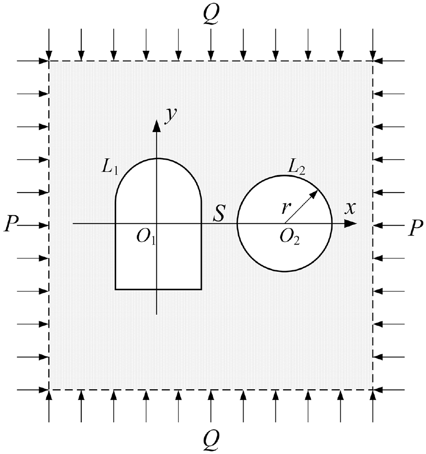
Cross-section of a tunnel and a circular hole in an infinite and elastic rock mass.
In Muskhelishvili’s complex variable method, stress function for plane elastic problem can be expressed by two analytical functions, which are


The general stress boundary condition is mostly expressed in terms of integration:

The rock mass should lie left while integrating.


For constant does not contribute to the stress,
As to the problem considered in this paper, the two analytical functions have the following forms:


where
3. Conformal mapping
It is impossible to calculate out the two analytical functions from the stress boundary conditions in their current form. Conformal mapping should be conducted to simplify the problem. Referring to our earlier research [13], two steps are needed to map the region (shown in Figure 1) into an annulus.
In the first step, the infinite plate with a tunnel and a circular hole (see Figure 2(a)) should be mapped into an infinite plate with two circular holes (see Figure 2(b)). However, the form of the mapping function we proposed is no longer suitable for this problem because there does not exist a common symmetrical axis. Through our research, we found that the mapping function which maps an arbitrarily shaped hole into a circular hole can manage the discussed problem here, whose form is as follows:

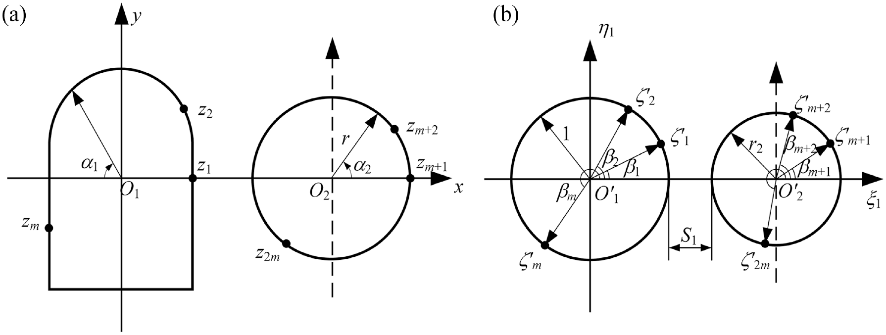
First step of the conformal mapping. (a) z plane with a tunnel and a circular hole and (b)
For almost all the cases of single tunnel problems, the coefficients of the above formula, namely, λ1, λ0, and λ −k (k = 1, 2, 3, …), are the real numbers or pure imaginary numbers. Without a common symmetrical axis for the two holes, the coefficients are complex numbers in this paper. Although the mapping function is much more complicated, it also can be figured out by optimization methods while λ −k is truncated at a countable number k.
Set the radius of the image circle mapped from the tunnel be 1. Let the radius of the image circle mapped from the cavity be r2 and the distance between the edges of the two circles be S1 (see Figure 2(b)). r2, S1, λ1, λ0, and λ -k are undetermined which can be found out through the correspondence between the coordinates before and after the mapping, and the solving process is as follows.
Select m points on each hole boundary in Figure 2(a) (the inflection point should be included), assume that they are, respectively, mapped into points

Let:
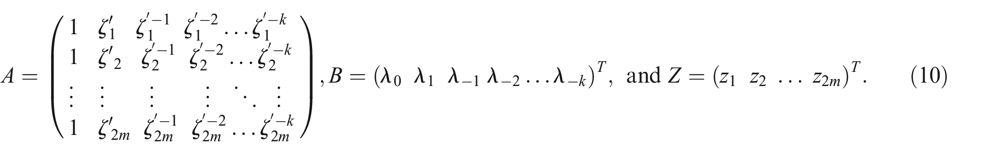

Noticing that equation (9) is a set of linear equations with the form

B can be figured out by:

where
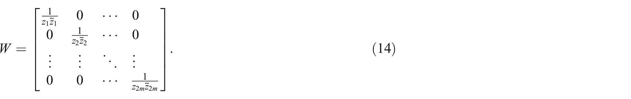
For r2, S1
However, linear equations may have no solution, the solution derived by the least square method is approximate, namely, that the equality constraints may do not hold. Hence, we use the penalty function method to optimize design variables X to make all of the equality constraints hold, where

The angles in local coordinates should satisfy the following inequality constraints which need to be included in the optimization:
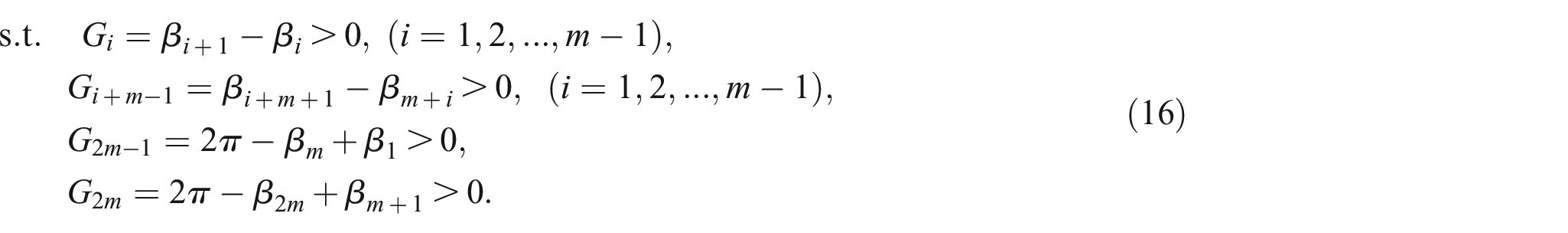
Add the inequality constraints penalty term to the objective function to obtain the penalty function:

where
Give initial values of
Use Davidon-Fletcher-Powell algorithm to minimize
If
Let
The equality constraints (equation (9)) will hold through optimizing
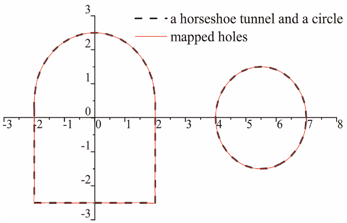
Contrast between actual hole shape and mapped hole shape.
Coefficients of the mapping function for holes in Figure 3.
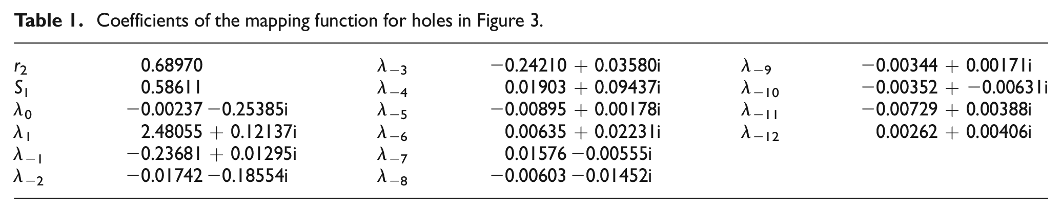
The mapping function maps Figure 2(b) into Figure 2(a). The giving actual hole shape is in agreement with the mapped shape, which is shown in Figure 3.
Then, the first step of mapping is completed. The second step is to map the two circles into a ring (see Figure 4), and the function is known to be:

where
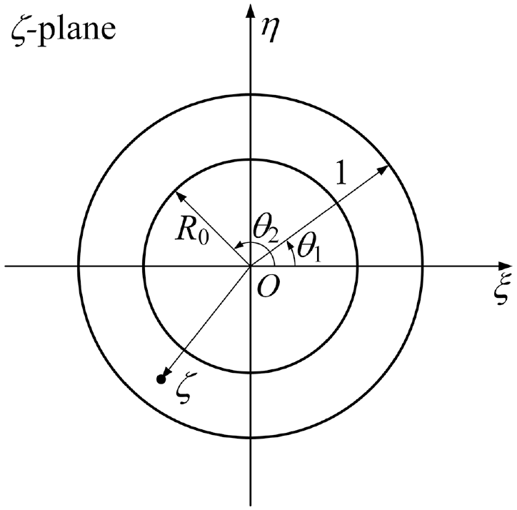
An annulus in image plane.
Substituting equation (18) into equation (8) obtains the complete mapping function:

4. Solving the two analytical functions
Once z plane is transformed into ζ plane, the two single-valued analytical functions


where aj, bj, cj, and dj are unknowns.
The two analytical functions will be much more easily solved in ζ plane. Taking advantage of equations (19)–(21), the two stress boundary conditions are transformed as:


where σ represents the coordinate on the outer boundary, and R0σ represents the coordinate on the inner boundary in Figure 4.
If the stress boundary conditions


The fractions in equations (24) and (25) should be eliminated to obtain the equation set which could directly solve the coefficients (aj, bj, cj, and dj). It is obvious that


What should be mentioned is that the coefficients (
As to equations (24) and (25), the following equations can be easily deduced:


Substituting equations (26)–(33) into equations (24) and (25), equations (24) and (25) can be written as:
The coefficients (aj, bj, cj, and dj) can be obtained from equations (34) and (35) for the equalities of the two equations should hold for every σ. Therefore, the coefficient of every power of σ in the left sides of the two equations should equal the coefficient of the same power on the right sides. Since the right sides of equations (34) and (35) are known, an equation set related to the coefficients (aj, bj, cj, and dj) can be established.
The left sides of equations (34) and (35) contain infinite power items for
Based on the above assumption, the unknowns that should be calculated out are a0 + c0 − cA, a0 + c0, a1∼aN, b1∼bN, c1∼cN, and d1∼dN. Since a0 and c0 do not contribute to the stress, constant terms a0 + c0 − cA and a0 + c0 do not have to be calculated out. Then, the equation set related to a1∼aN, b1∼bN, c1∼cN, and d1∼dN can be established by equating the coefficients of

where
Once the two analytical functions are solved, the stress components in the image plane, described by orthogonal curvilinear coordinates, can be obtained from equations (1) and (2):


5. Comparison with ANSYS solution and stress result around the holes
Highly complicated equation deductions and solving large sparse linear equations are necessary to derive the analytical stress solution. Comparison with ANSYS solution is made to validate the correctness of deductions and solving process. Despite stress solution obtained from ANSYS being approximate, the stress distributing regularity is roughly right. So, the comparison is meaningful.
The example used for comparison is shown in Figure 5(a), in which the height of the straight side wall and the radius of the semicircle are both 2 m, the radius of the cavity is 1.5 m, and the horizontal stress P and vertical stress Q are set as 0.5 and 1.0 MPa, respectively. The ANSYS plane model is a big square with its side measuring 80 m to simulate the infinite domain. Using Plane2 element to mesh the area obtains 503,603 nodes and 251,122 elements in the numerical simulation process. The tangential stresses of the points of every degree on the two boundaries calculated by two methods are shown in Figure 5(b). The numerical solution and the analytical solution are in good agreement except the two corner points. The two biggest differences appear at 231° and 309°, and the relative error is about 10%. It is mainly because the tangential stress varies too fast at the corner while the ANSYS constant-stress element has an area.
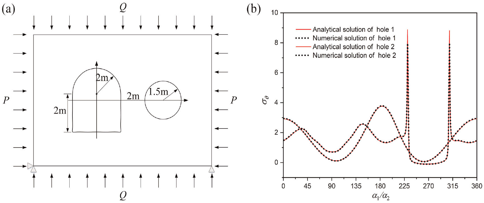
Comparison between numerical solution and analytical solution. (a) ANSYS model and (b) contrast of tangential stress on the boundaries.
To demonstrate the stress result around the holes of this case, stress cloud maps of
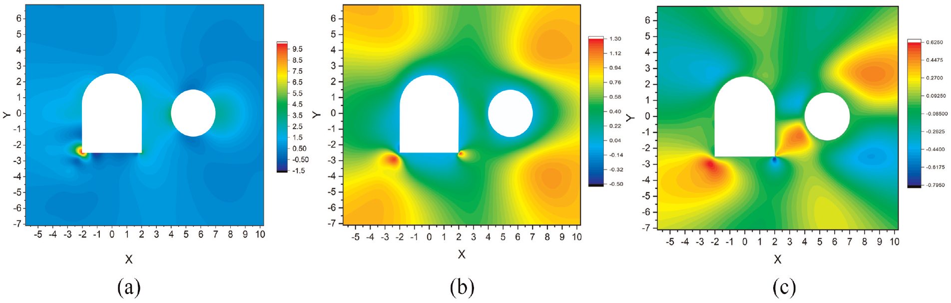
Stress cloud maps of (a)
The largest stress concentrations appear around the tunnel corners where the tangential stress is much larger than the two other stress components. And it can be found from Figure 6 that the area of great stress concentration of left corner is bigger than that of right corner.
6. Examples
Using the method proposed above, the stresses in the plane are calculated out for some situations. But only the tangential stress is showed in figures because of its importance.
6.1. Effect of lateral stress coefficient
The geometry is chosen the same as which is in section 5. The imposed vertical stress Q is set as 1.0 and three different horizontal stresses P: 0.5, 1.0, and 1.5 are considered to investigate the influence of axial stress on tangential stress. The obtained stress distribution on the boundaries of the two holes is demonstrated in Figure 7 by every 1°.
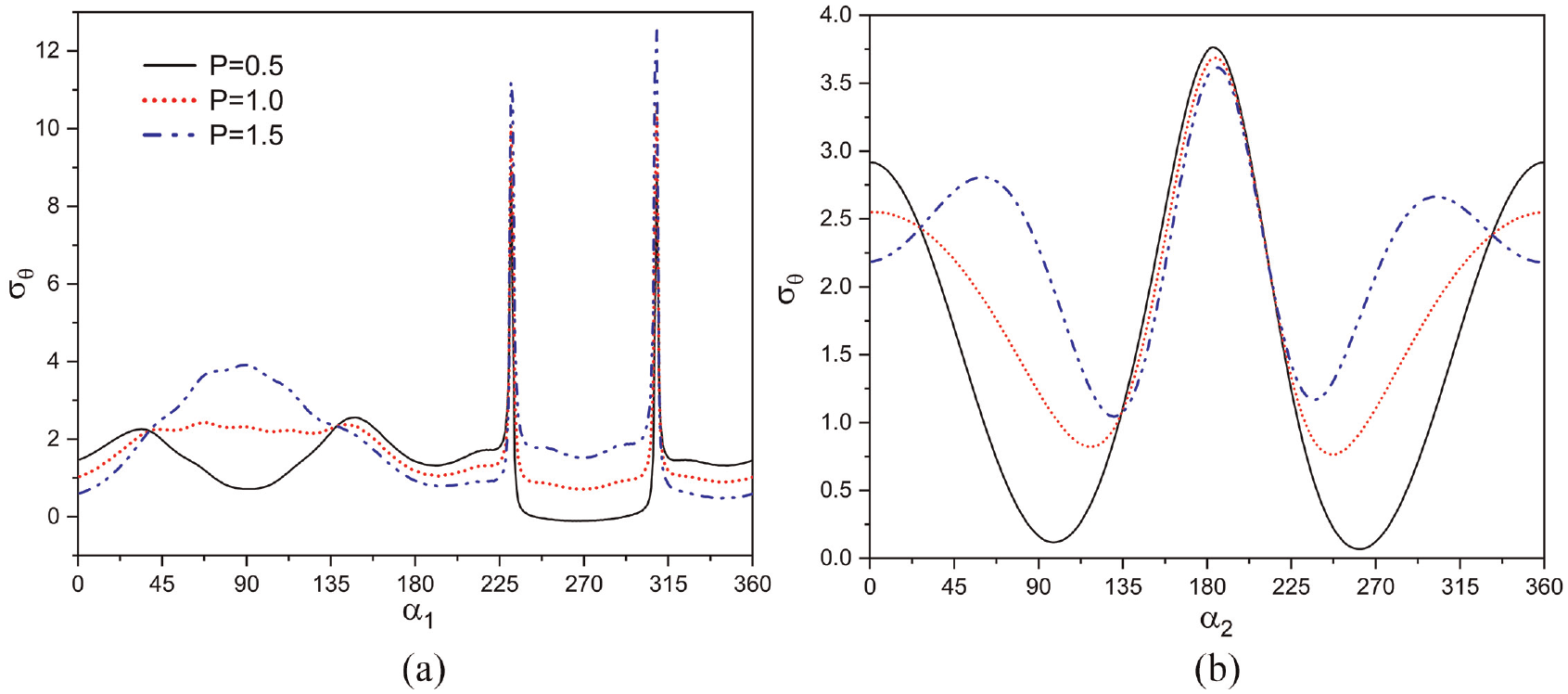
Tangential stress for different lateral stress coefficients: (a) left hole and (b) right hole.
Figure 7(a) shows the tangential stress on the boundary of the tunnel. The stress values at the two corner points, namely, 231° and 309°, are much larger than other locations. And they increase as the horizontal stress increases, for instance, the stresses at right corner are 8.86, 10.69, and 12.54 when horizontal stresses are 0.5, 1.0, and 1.5, respectively. The tangential stress at right corner is bigger than the left one for the existence of the circular hole. The tangential stresses at the vault (about
Figure 7(b) shows the tangential stress on the boundary of the circular cavity. The stress distribution of the circular hole is nearly symmetric with respect to
There are four points on the either boundary at which tangential stress is zero under only horizontal stress. This phenomenon exists in all of the two hole problems [12,13].
6.2. Effect of distance of the two holes
Three distances of the two boundaries are investigated here: S = 1, S = 3, and S = 9 when the other shape parameters are kept the same as section 5. Generally, the effect of distance differs with respect to applied load, so two uniaxial loads—horizontal stress and vertical stress—are discussed here.
Figure 8(a) illustrates the tangential stress distribution on the tunnel boundary for different distances while the plate is under horizontal stress. The stress remains largely unchanged when the cavity moves away from tunnel. Tangential stresses are tensile at range
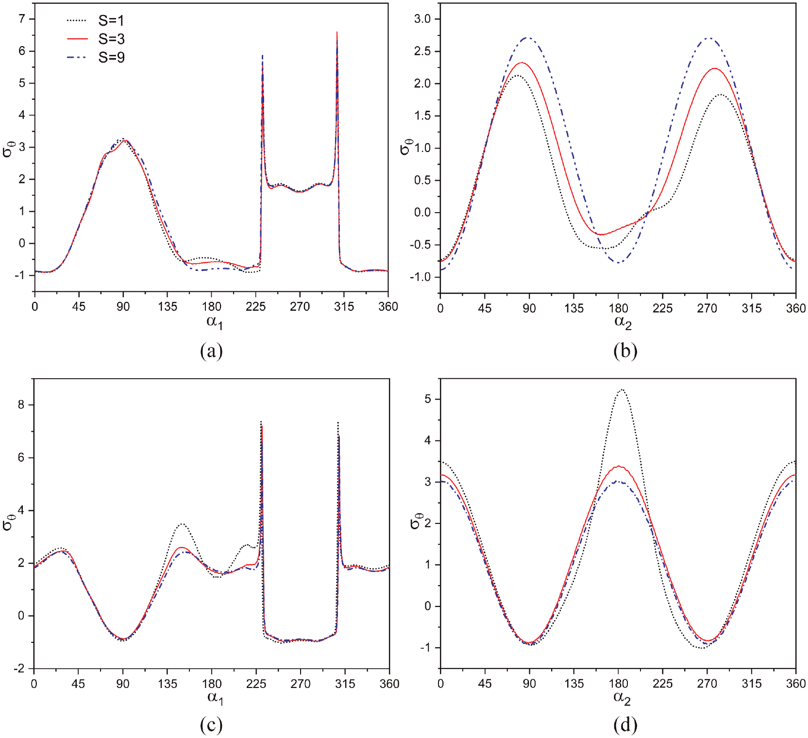
Tangential stress for different distances of the two holes. (a) Left hole, P = 1.0, (b) right hole P = 1.0, (c) left hole, Q = 1.0, and (d) right hole Q = 1.0.
The change of tangential stress on the tunnel due to different distances while under vertical stress is presented in Figure 8(c). Similarly, it varies little except the stress fluctuation at
6.3. Effect of the size of circular cavity
Sometimes in karst area, tunnel and circular karst cave are arranged in parallel and the karst cave will enlarge over time. It is interest to investigate the changement of stress due to the size of circle. In this part, the tunnel geometry and distance of the two holes are kept the same as section 5 while three circle radii—0.5, 1.5, and 3.0—are considered.
Figure 9(a) demonstrates the tangential stress around tunnel boundary for different circle radius while under horizontal stress. With the enlargement of the circular hole, the stresses at the right side wall increase, the stresses at right side of arch and stresses at the floor decrease. In particular, the tangential stresses at left corner point reduce greatly, which are 6.27, 5.52, and 3.31 here. The stress distribution on the boundary of round cave is shown in Figure 9(a). With the increasing of the circle size, tangential stresses at about the range
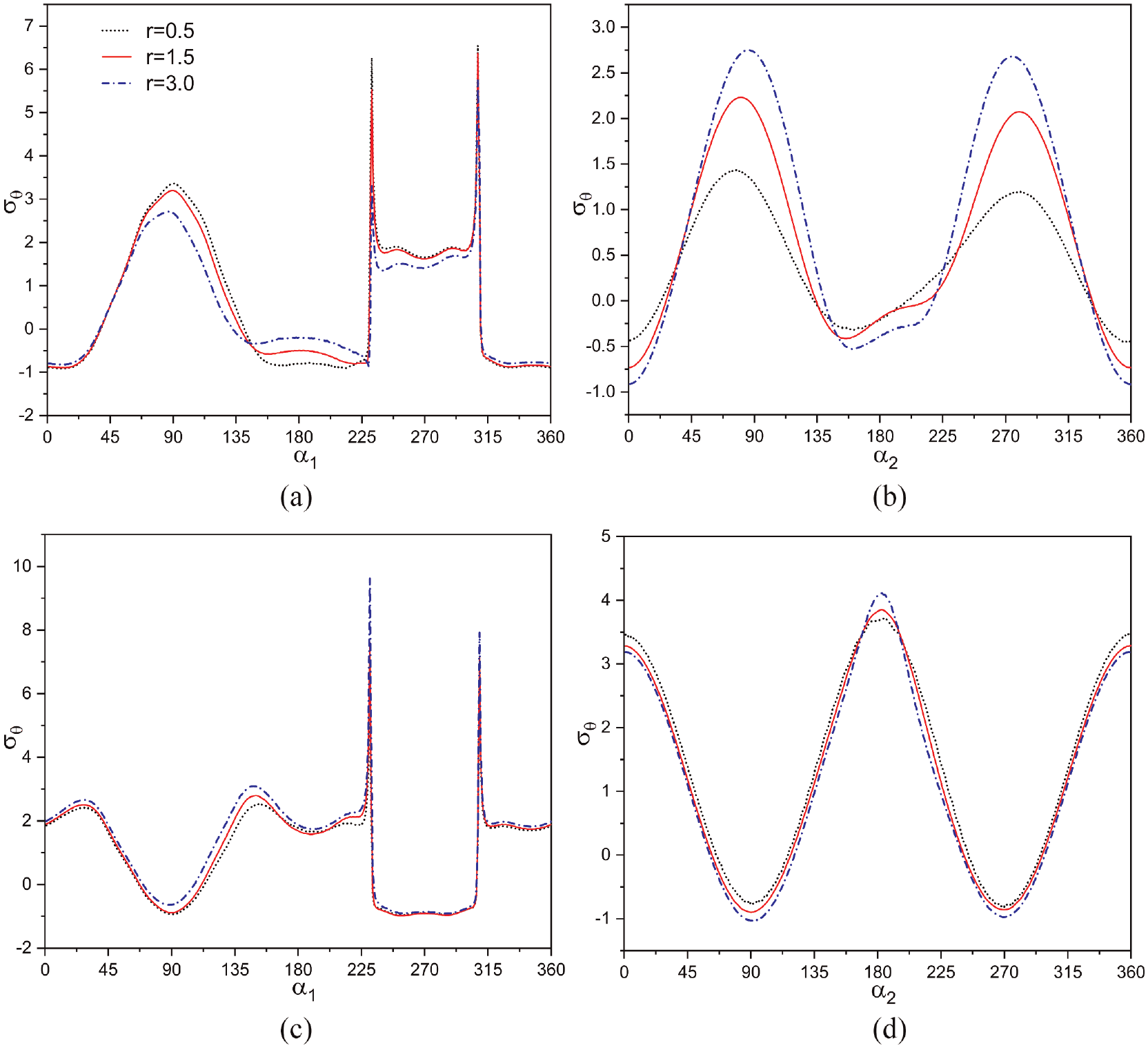
Tangential stress for different sizes of the cavity. (a) Left hole, P = 1.0, (b) right hole P = 1.0, (c) left hole, Q = 1.0, and(d) right hole Q = 1.0.
Figure 9(c) and (d) presents the tangential stress distribution on the tunnel boundary and circular hole boundary while under vertical stress, respectively. In this load condition, tangential stress on both boundaries changes little while the circle size increases except tangential stress at tunnel corner increasing remarkably, for instance, the stresses at left corner are 6.45, 7.61, and 9.63 for radius are 0.5, 1.0, and 1.5, respectively.
6.4. Effect of the position of circular cavity
As to practical tunnel engineering, the cavity may be located in any position in the plane. To study the effect caused by the position of circle, four cases are calculated (see Figure 10), which the angles of the connecting line (O1O2) of the two hole centers with respect to x-axis are −90°, −30°, 30°, and 90°, and the distance of two hole centers and the sizes of tunnel and cavity are the same as section 5.
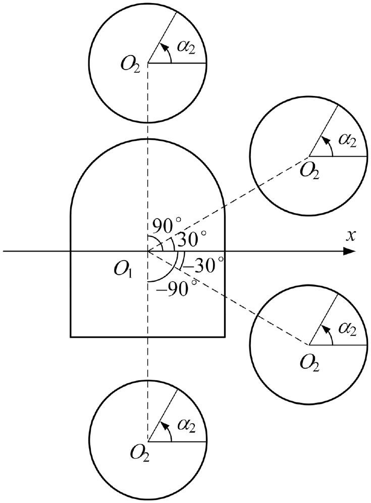
The tunnel close to a circular cavity of different positions.
Figure 11(a) and (c) demonstrates the tangential stress on the tunnel boundary when the plane is applied horizontal stress and vertical stress, respectively. The stress almost remains unchanged except little change appearing at the right side wall and floor of the tunnel.
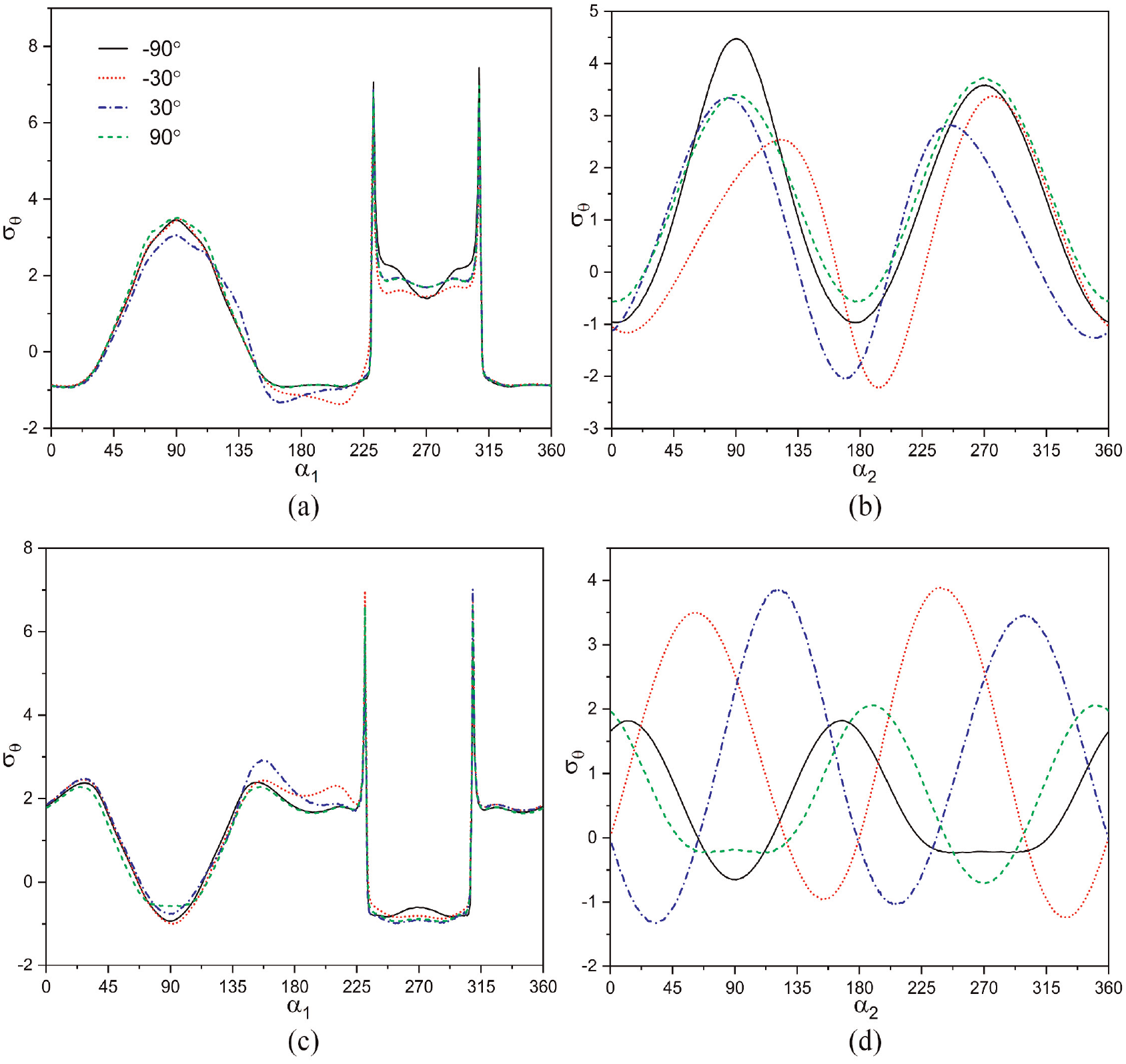
Tangential stress for different positions of circular cavity. (a) Left hole, P = 1.0, (b) right hole P = 1.0, (c) left hole, Q = 1.0, and (d) right hole Q = 1.0.
Figure 11(b) and (d) displays the tangential stress on the cavity boundary when the plane is applied horizontal stress and vertical stress, respectively. To compare the stress variation of the same point, the angles are measured from the same position in the circle shown in Figure 10. The stress distributions of cavity differ largely from its position. While under horizontal stress, the maximum tangential stress occurs at the top or bottom of the circle and the maximum tensile stress is located at
7. Conclusion
This paper is based on a new discovery that the mapping function of an arbitrarily shaped hole can also manage a tunnel and a circular hole mapping into two circles. With the technique of least square method embedded in mixed penalty function method, the coefficients of the mapping function can be found through optimization. Combined with Korn’s function, the two holes can be finally mapped into a ring. Then, stress boundary conditions are established by two analytical functions which are solved by the power series method. And ANSYS simulation is conducted to compare with the analytical solution, which they are in good agreement. Some numerical examples are calculated out to study the effect by parameters, and tangential stress distributions on the boundaries are plotted in the figures. The method is applicable to problem of an arbitrarily shaped hole near to a neighboring circular cavity. However, since the mapping functions should be analytic, the hole boundary must be smooth curves and the solution near the sharp corner is approximate which is acceptable for tunnel engineering.
Undoubtedly, the corners of the tunnel are the places where the largest stress concentration is located in. And the stress at the two corner increases as the horizontal stress increases. The side wall of tunnel will produce tensile stress when the plane is subjected to horizontal stress and the vault and floor of the tunnel appear tensile stress when the plane is under vertical stress. The circle size has great effect on the boundary stress. With the enlargement of the circular hole, the maximum stress at the corners decreases while under horizontal stress and it is just the opposite while under vertical stress. The distance of the two holes slightly affects the stress on the tunnel while the stress on the left part of the circular hole is larger for small distance under vertical stress. The position of circle also influences the stress on the tunnel little, but the stress distribution on the circle varies considerably for its different position.
Footnotes
Declaration of conflicting interests
The author(s) declared no potential conflicts of interest with respect to the research, authorship, and/or publication of this article.
Funding
The author(s) disclosed receipt of the financial support for the research, authorship, and/or publication of this article: This work was supported by the Natural Science Foundation of China (grant no. 52108370) and the Jiangxi Provincial Natural Science Foundation (grant no. 20212BAB214062).