Soft matter mechanics generally involve finite deformations and instabilities of structures in response to a wide range of mechanical and non-mechanical stimuli. Modeling plates and shells is generally a challenge due to their geometrically nonlinear response to loads; however, non-mechanical loads further complicate matters as it is often not clear how they modify the shell’s energy functional. In this work, we demonstrate how to form a mechanical interpretation of these non-mechanical stimuli, in which the standard shell strain energy can be augmented with potentials corresponding to how a non-mechanical stimulus acts to change the shell’s area and curvature via the natural stretch and curvature. As a result, the effect of non-mechanical stimuli to deform shells is transformed into effective external loadings, and this framework allows for the application of analytical and computational tools that are standard within the mechanics community. Furthermore, we generalize the effect of mass change during biological growth to account for its effect on the stress constitution. The theory is formulated based on a standard, stress-free reference configuration which is known a priori, meaning it can be physically observed, and only requires the solution of a single-field equation, the standard mechanical momentum or equilibrium equation, despite capturing the effects of non-mechanical stimuli. We validate the performance of this model by several benchmark problems, and finally, we apply it to complex examples, including the snapping of the Venus flytrap, leaf growth, and the buckling of electrically active polymer plates. Overall, we expect that mechanicians and non-mechanicians alike can use the approach presented here to quickly modify existing computational tools with effective external loadings calculated in this novel theory to study how various types of non-mechanical stimuli impact the mechanics and physics of thin shell structures.
Soft matter deforms in response to a variety of stimuli, which may include biochemical signaling during growth [1–11], voltages applied to electroactive polymers [12–21], residual stresses that build up during three-dimensional (3D) printing [22–26], externally applied magnetic fields [27–34], interactions with surrounding granular matter [35–40], and swelling with fluids [41–53]. Modeling such interactions and deformations presents a variety of challenges. One may write down the field equations corresponding to a given stimulus; however, simultaneously solving multiple field equations to capture tightly coupled multiphysics phenomena generally requires significant computational expense, as well as complex and specialized numerical formulations. Adding to that challenge are the finite deformations common in soft materials and the geometric nonlinearity and instabilities of slender structures. Taken together, this presents a formidable challenge for modeling the behavior of stimuli-responsive materials.
We know that the equilibrium configurations of a structure, and the stability of these equilibria, can be determined through the analysis of its total potential energy. The total potential energy is composed of the strain energy stored in the deforming body, along with any potentials due to external mechanical forces and moments that are acting on it. Here, we are concerned with thin shells—curved structures whose thickness is small compared to their other two spatial dimensions. Koiter’s foundational contributions to shell theory throughout the middle of the 20th century showed that the strain energy stored within a deforming shell may be decomposed into separate contributions from stretching and bending the shell’s middle surface [54–58]. The principle of minimum potential energy ensures that equilibrium configurations of a shell are found by extremizing the total potential energy, a process aided by the calculus of variations, where equilbria are found when the first variation of the total potential energy vanishes. The stability of these equilibrium configurations is then determined by the character of high-order variations of the total potential energy—it is commonly sufficient to check the second variation, with stable equilibria having a second variation that is positive-definite. A common challenge is encountered when a shell is subjected to non-mechanical stimuli, for instance, thermal, swelling, electrical, or growth—namely, how do we write the total potential energy for shells subjected to these stimuli? These problems are particularly important in the study of soft matter, where non-mechanical stimuli can cause extremely large deformations and may result in elastic instabilities.
For multi-physics systems, many theories have been actively developed to describe the behavior of 3D solid bodies subject to non-mechanical stimuli. They can be classified into three types: diffusion models [59–68], continuum elastic models [69–75], and mixture models [76–79]. Despite this ongoing research, a relatively small number of attempts have been presented to apply those modeling theories for thin bodies [80–88] and to develop modeling theories of plates and shells subject to non-mechanical stimuli [89–95]. Meanwhile, great strides were made in modeling stimuli-responsive plates through the introduction of the so-called non-Euclidean Plate (NEP) theory [90, 96–100]. In this approach, the strain energy of an elastic plate is calculated by considering the difference between the deformed configuration of the plate and the “stress-free” configuration of the plate. This intermediate stress-free configuration is distinct from the initial configuration and is in general incompatible—meaning it cannot be physically observed. This presents a practical challenge for modeling stimuli-responsive plates and shells: the intermediate configuration is very complex and difficult to conceptualize even for plates exposed to simple stimuli. As we will show, this work recasts NEP theory in a more traditional mechanical framework, that is, strains are measured with respect to the reference configuration that is known a priori, rather than the intermediate configuration. However, we are not altogether done with the intermediate configuration. In what we will put forth as a stimuli-responsive shell (SRS) theory, the intermediate configuration enters in the potential of the effective external loads, which are conjugate to the non-mechanical stimuli that act to stretch and bend the shell. In this framework, it becomes far easier to conceptualize the intermediate configuration as it is only necessary to consider how the stimuli deform a beam, whose intermediate configuration is compatible, rather than a shell, whose intermediate configuration is not.
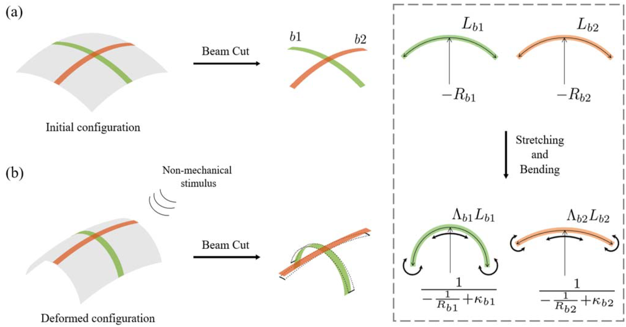
At every point on the shell, one may imagine cutting two orthogonal beams from the surface as shown in Figure 1. Removed from the geometric constraints of the shell’s surface, these beams are free to deform in response to stimuli that act to stretch or bend them. A non-mechanical stimulus may cause the neutral axis of these beams to stretch or bend, deformations that we refer to as the natural stretch and natural curvature, respectively. This way of conceptualizing the effect of a stimulus is not merely a gedanken experiment, but can in fact be used to experimentally measure the natural stretch and natural curvature that a shell experiences [48, 51, 101] and is analogous to common biological measurements of residual stress within soft tissues [102–109]. As such, these quantities will form the basis for the SRS theory that follows. Beyond stretching and bending, non-mechanical stimuli may add mass to the shell—an effect that occurs in problems involving biological growth [110–113] and when a soft material is swollen by a macromolecule, such as a polymer chain [47, 114, 115]. As we will show, accounting for the addition of material to a shell requires a subtle accounting of how that mass changes the shell’s free energy, and we put forth a generalized framework for adding mass—either similar or dissimilar—to the existing shell.
Schematic of two orthogonal beams ( and in the figure) cut from a surface. (a) Beam cut from the initial configuration with initial length ( and ) and radius of curvature ( and ). (b) Beam cut from the deformed configuration upon application of a stimulus, which shows the emergence of natural stretch ( and ) and natural curvature ( and ) under the assumption that the natural stretch and curvature are homogeneous along each beam cut, which itself is sufficiently narrow to be free of any constraints. The dotted shapes of the isolated beams denote the original beam cut before the geometric constraints are released.
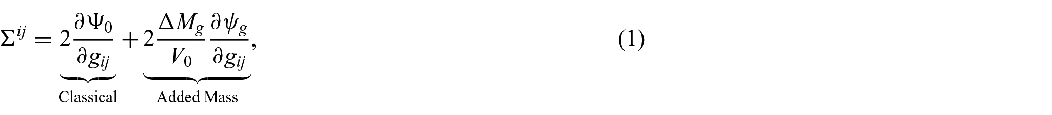
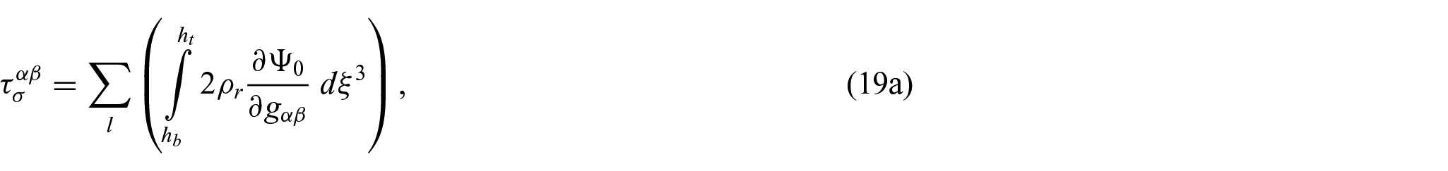
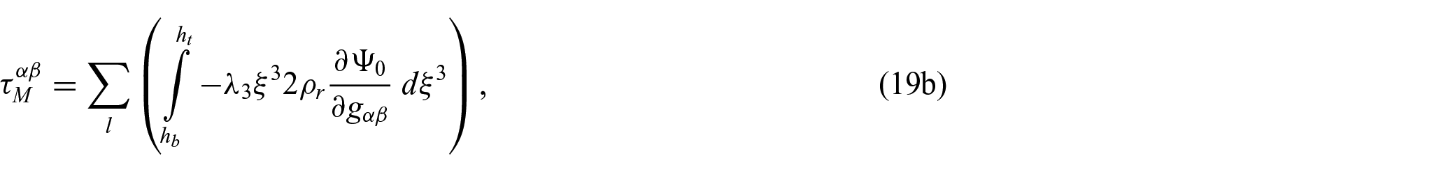
In this work, we put forth a general shell theory to account for non-mechanical stimuli. We consider three generic forms of stimuli: (1) one that adds mass to the shell, (2) one that acts to increase the area of the shell (locally or globally), and (3) one that acts to change the curvature of the shell (locally or globally). We will show in Section 3 on thermodynamics and conservation of mass that when mass is added to an elastic body, it alters the internal energy density and the state of stress. As a result, the second Piola–Kirchhoff stress —which is typically found by differentiating the strain energy density per unit volume with respect to the metric tensor—is modified to account for a change in mass relative to the shell’s original volume according to
where is the energy density form with no mass addition using the material properties of the initial body, and is the 3D metric tensor of the current (deformed) configuration. On denoting the free energy, the subscript indicates that the added mass may or may not be the same material as the mass of the original shell—a different material will also have a different free energy, and therefore different mechanical properties. In general, when mass is added locally to a shell, for instance, through biological growth, this added mass will increase the shell’s state of stress. Furthermore, if the material added during growth is different from what is already present in the body, this will change the material properties [111, 116, 117], which has significant ramifications for deformation and material stability. We note that the formulation we present is more general than previous work [72], which always gives the same stress amplification for all types of stimuli due to its geometric dependence on changes in the area or volume of the material.
The primary contribution of this paper is the mechanical interpretation of non-mechanical stimuli, which will be shown in Section 5. Therefore, one may take the strain energy of a plate or shell (e.g. Föppl–von Kàrmàn; Donnell–Mushtari–Vlasov; Koiter) and add to it a potential corresponding to how a non-mechanical stimulus acts to change the shell’s area, , and a potential corresponding to a stimulus that acts to change the shell’s curvature, , that is,
as is standard for work from mechanical loads, with the initial area element . Non-mechanical stimuli that act to stretch an area of the shell are characterized by a natural stretch, which is work conjugate to the stretching strains of the shell’s middle surface which correspond to an intermediate stress-free configuration, . The natural stretch will be a scalar if it is uniformly acting over the shell, but in general, it will appear as a second-order tensor , and as we will show, the potential of natural stretch is
As you may expect, the thickness enters linearly, and the strain tensor and natural stretch are associated with the elasticity tensor in the reference configuration, as neglecting changes in the energy due to differences in metric tensors corresponds to the largest principal extension in the stress-free state from the initial body. An example of a non-mechanical stimulus that imparts a natural stretch would be a shell that is growing uniformly through its thickness. If a shell is experiencing differential growth, where the outer surface of the shell is growing more or less than the inner surface of the shell, this will generate a natural curvature that is a generalization of Timoshenko’s heating of a bimetallic strip. This stimulus acts to locally change the curvature of the shell and is in general a second-order tensor . The natural curvature is work conjugate to the curvature strains of the shell’s middle surface which correspond to an intermediate stress-free configuration, , such that the potential of natural curvature is
where, as you may expect, the potential of natural curvature scales as the cube of the shell’s thickness.
Our intent is to make analytical and computational modeling of shells exposed to non-mechanical stimuli generic and approachable with the tools and techniques common to theoretical and applied mechanics. As such, we also describe at length how to calculate the natural stretch and natural curvature from experimental measurements. The scalar forms of and will be somewhat familiar to readers well-versed in Timoshenko’s bimetallic beam theory. As we will show for a bilayer shell, both and depend on the relative expansion factor of each layer, the modulus ratio, the thickness ratio, and the stress amplification due to mass addition. The expansion factor is perhaps the least familiar, but it simply involves measuring how much the distance between material points has changed in response to a non-mechanical stimulus.
As is common with shell theories, our efforts focus on projecting the effects of these stimuli onto the middle surface of the shell. While we discuss and in the context of bilayer shells, this SRS theory can be applied to a shell with an arbitrary number of layers through the thickness. In Section 4, we describe how to model a generic multilayer shell as an equivalent monolayer shell, where the stresses that result from stretching and bending the shell are projected onto the shell’s middle surface. We utilize the nonlinear kinematics of Koiter’s shell theory throughout this paper, as it allows us to validate our model on a variety of well-studied problems involving stimuli-responsive shells. In Section 5, the SRS theory is developed by mapping non-mechanical stimuli to effective mechanical stretching and curvature potentials. Using a variational principle, we derive the first variation of the total potential energy, which may serve as the weak form to be solved using the finite element method, as well as the second variation of the total potential energy, which may be used to check the stability of a given equilibrium configuration. The performance of this proposed shell theory is illustrated by several benchmark problems and verified by the available analytic solutions in Section 6. A benefit of mapping non-mechanical stimuli to effective mechanical potentials is that the resulting total potential energy (i.e. equation (2)) is amenable to linear stability analysis, perturbation methods, and other tools from analysis and applied mathematics. We demonstrate this in Section 7, where we look at several example problems analytically and computationally. These include the growth of a leaf (which involves natural stretching), the rapid closure of the Venus flytrap’s leaves (which involves natural curvature), and the buckling of a plate made of a dielectric elastomer (which involves linear stability analysis). This SRS theory utilizes standard Kirchhoff–Love kinematics while accounting for nonlinearity. Because such details have been widely presented in previous works [54–58], we provide relevant background information in Appendices 1–3 while focusing the discussion in the main text on how to account for non-mechanical stimuli as equivalent mechanical stretching and curvature potentials, and how those potentials can be evaluated using common experimental measurements.
A brief note about notation. In what follows, the reader will encounter what Cartan [118] referred to as a “debauch of indices.” To make matters worse, in order to describe a deforming shell we must keep track of several curved configurations simultaneously. We begin with a reference configuration (which may also be referred to as the original, initial, or undeformed configuration). Quantities associated with the reference configuration will be denoted with an overcircle, for example, . Quantities associated with the current or deformed configuration of the shell will have no decoration above them, for example, . The differential geometry of surfaces tells us that shells often cannot directly adopt the shape prescribed by a given stimulus, meaning that the deformed configuration—the one that will be observed in practice—will possess a residual state of stress. This motivates the consideration of a third configuration that describes the stress-free (or natural) state of the shell, one that may be impossible to physically realize but nonetheless provides an essential means for performing calculations. Terms associated with this surface will be denoted with an overbar, for example, . To make matters worse, a general surface containing multiple layers through its thickness requires us to keep track of the stress-free configuration of each layer, which we will denote with an over-tilde, for example, . Shells by definition are not flat and as such require curvilinear coordinates, as opposed to Cartesian coordinates, to describe material points in space. Switching between different shell surfaces, for example, , requires us to change our basis, which requires to keep track of how components transform under a change of basis, with covariant components (lower indices) changing in the same way as the basis, for example, a gradient operator, and contravariant components (upper indices) changing inversely with a change in basis, for example, a velocity vector. We employ Einstein’s summation convention, where we sum over repeated indices—a contraction between a covariant component and a contravariant component. For a primer on the underlying differential geometry, the reader is referred to Needham [119]; for a brief on tensor analysis, the reader is referred to Simmonds [120]; and for the governing shell theory, the reader is encouraged to examine Koiter’s [54–58] work and Niordson’s [121] book. In this paper, Latin indices take 1,2,3, and the Greek indices are restricted to 1,2.
2. Kinematics with the multiplicative decomposition of deformation gradient
There has recently been significant interest in using the multiplicative decomposition of the deformation gradient as a means for accounting for the effect of non-mechanical stimuli, such as heating, swelling, and biological growth, on the mechanical response of structures and materials [59, 69, 71, 110, 112, 122, 123]. In this approach, the 3D deformation gradient, which is a one-to-one mapping of a material point in the initial configuration to a material point in the current (deformed) configuration , is composed as , where and are the mechanical (elastic) and non-mechanical parts, respectively. The non-mechanical part of the deformation gradient constructs a conceptual intermediate (stress-free) state as the mapping of the initial material points to the intermediate material points . Here, we use the term “state” rather than using “configuration” as the intermediate configuration cannot be realized if the deformation gradient does not uniquely define a one-to-one mapping, that is, incompatible. Meanwhile, the elastic part of the deformation gradient describes elastic deformations that satisfy the linear momentum balance on the deformed configuration, for which stresses are calculated via a relation between the current configuration and its corresponding intermediate state at local points. Then, the internal term of mechanical potential energy is calculated by means of the elastic part of the deformation gradient, that is, deformation from the intermediate stress-free state.
To apply this approach to the thin-shell kinematics, we begin with the 3D covariant tangent vector that is obtained via the parametric derivative with respect to a material point on the surface of a 3D body, for example, for the current configuration, based on the differential geometry with the general coordinate system using the curvilinear coordinates embedded in the body. The covariant components of the 3D metric tensor, including information about the distance between the material points, are calculated as for the current configuration, from which the dual vector is with such that is the Kronecker delta. All differential geometry calculations can be also applied for the initial configurations, denoted with the over-circle notation, for example, , , , , and . Meanwhile, the 3D metric tensor of the intermediate stress-free state can be calculated as , where based on the definition of the non-mechanical part of deformation gradient as . This indicates that the stress-free 3D metric tensor is determined by the initial geometry and the specific form of which depends on the stimulus type and profile. The dual vector is calculated as with such that . Here, we use the over-tilde notation for the differential geometry calculation in terms of the intermediate state, for example, , , , , and .
As the elastic deformation is represented through the mechanical part of the deformation gradient, the elastic Green–Lagrange strain tensor is obtained as
with the mechanical (elastic) right Cauchy–Green tensor and the second-rank identity tensor .
For thin surfaces, as the transverse shear deformations are negligible, the Kirchhoff–Love shell assumption that the normal vector of the mid-surface remains normal to the mid-surface after deformations is applicable to describe the geometry of thin shells [124]. Hence, Kirchhoff–Love shell kinematics are employed in this paper to describe our target geometry, that is, soft, thin shells. When a general thin surface is considered in 3D space, its material points are described by a general mapping from the parametric domain [125]. With the curvilinear coordinates , the general mapping of the current surface’s mid-surface is expressed as so that a material point on the surface of a 3D body can be described as with the thickness-direction coordinate where is the thickness-change ratio between the current and initial surface, is the surface unit normal vector, and is the initial surface thickness. In this paper, a change in thickness during elastic deformation is allowed for the sake of generality and calculated using the plane-stress condition owing to the thin thickness of shells. We note that most thin-shell theories assume a constant thickness during the elastic deformation using the plane-strain condition and the plane-stress condition. Based on the parameterization of the surface, the covariant tangent vector on the current mid-surface is obtained using the parametric derivative as
Using the covariant tangent vector, the metric tensor (first fundamental form) of the current mid-surface, which has information about the lateral distance between material points on the mid-surface, is obtained as
The dual vector is calculated as with such that . The unit normal vector to the current mid-surface is obtained as
which is called director in the Kirchhoff–Love shell theory. A projection of this surface unit normal vector on the mid-surface gives information about the local curvature of the current mid-surface through the curvature tensor (second fundamental form) as
The third fundamental form is also defined as .
Similar to above, all differential geometry calculations on the mid-surface can be also applied for the initial configuration and will be, in this paper, denoted with the over-circle notation, for example, , , , , , , , and .
From the shell kinematics, the 3D metric tensor for the current and initial surface body can be expressed using the fundamental forms on the mid-surface as
where is negligible due to the thin thickness of the shell. Assuming that the intermediate stress-free 3D metric tensor has a similar form for its in-plane components as yields
where and are, respectively, the membrane and bending strain on the mid-surface, with the fundamental forms on the mid-surface of the intermediate stress-free state from the differential geometry given by
3. Material constitutive response accounting for mass change during biological growth
In biological growth problems, an important phenomenon that should be considered in the growth modeling is mass change, as the growth increases the structural size by means of mass addition. That is, the deformation during growth is determined by the mass uptake at growing parts in the body, and thus, mass is a variable that impacts the strain energy density per volume. As discussed in Lee et al. [113], since the internal stress of the body is calculated as the derivative of the strain energy density with respect to strain, it is clear that the mass uptake should impact the internal stress state. In this section, we will elaborate on the concept of how mass addition during growth alters the stress state in a growing body and generalize it to represent the resulting internal stress for all types of stimuli, regardless of whether the mass is added or not.
From thermodynamics, the stress constitutive equation for the second Piola–Kirchhoff stress is derived based on the energy balance and the dissipation inequality (see Appendix 2 for detailed derivation) as
with the basis vector on the initial configuration, in which is the Helmholtz free energy per mass, is the 3D metric tensor of the current configuration, is the Jacobian for the deformation gradient , and is the current mass density per current volume. If there is no mass uptake, is equal to the initial mass density from mass conservation, so the second Piola–Kirchhoff stress is calculated as , where is the energy density form with no mass addition using the material properties of the initial body. In contrast, if mass uptake occurs, for example, during biological growth, . Thus, the interpretation of has to be established to quantify the effect of mass uptake on the internal energy density and stress.
We consider an infinitesimal element at a material point in a body at which the current mass density can be expressed as , where and are the mass and volume of the infinitesimal element on the current configuration. Since the current mass is , where is the initial mass and is the mass increase due to biological growth, can be calculated as , where is the volume of the corresponding infinitesimal element in the initial configuration. Then, the stress constitutive equation can be rewritten as
where the second term is the stress modification that arises by accounting for a mass increase during biological growth. We denote the free energy corresponding to the newly added material as instead of just using because the newly grown material may have different characteristics than the existing material. The Helmholtz free energy that is a quantity “per mass” involves the mass density in the stress constitution. This stress constitution is closely related to material characteristics such as behavior types (e.g. hyperelasticity and viscoelasticity) and material properties (e.g. Young’s modulus and Poisson’s ratio). This implies that the form of free energy is determined by constituents composing the mass and indicates that if the newly grown materials consist of different constituents from the existing material, it requires the use of different free energy forms to describe their different material characteristics. Note that a negative value of implies shrinkage due to mass decrease. If the added mass is assumed to have the same mechanical behavior and properties as the existing material, the free energy of the new material has the same form as the free energy of the existing material, that is, . Then, the effect of mass uptake on the stress can be expressed through the density ratio , called stress amplification factor, as
Thus, the key result of equation (14) is that mass change due to biological growth results in a stress amplification factor of that modifies the state of stress in the body compared to standard continuum mechanics of that does not account for mass change, assuming that the added material is the same as that of the original body. Note that the density ratio also physically means the mass ratio between the initial and current mass after growth while we here keep using the density ratio instead of the mass ratio as density is a more standard variable in the mechanics field. We also note that the stress amplification factor derived in this section also intrinsically accounts for the stimulus types without mass addition because for those cases. Hereafter, in this paper, it is assumed that biological growth occurs with mass addition that has the same material behavior and properties as the existing body.
The derived stress amplification in this paper is similar to the work in Ben Amar and Goriely [72] in which the internal stress level is amplified with an extra factor of which only depends on the area or volume change of the material under consideration. However, as this extra factor is computed using elastic strains from the grown (intermediate) state, this approach gives the same stress amplification regardless of the stimulus type (i.e. heating, swelling, and biological growth), which can be problematic. For a simple example, when a material is swelling by water, the stiffness of the material will be decreased and the material will be softer. On the other hand, if the material undergoes growth by mass addition using the same material as the existing one through density-preserving growth, the stiffness of this material will be the same as before. Nevertheless, the extra factor of Ben Amar and Goriely [72] leads to the same amplification for these very different physical situations. In contrast to this, as the derived stress amplification in this paper is represented by the density ratio , it can describe the difference of the stiffness between the stimulus types concerning the mass addition—the case of no mass addition with comparable mechanical properties, such as heating and swelling, gives , that is, . We note that despite the different physical interpretations and mathematical origins of the stress amplification between this paper and Ben Amar and Goriely [72], our stress amplification factor generalizes the work of Ben Amar and Goriely [72] as the extra factor in Ben Amar and Goriely [72] is the same as our stress amplification for a specific situation where (1) the added material during growth is the same as the existing one; (2) the growth is density-preserving; and (3) elastic deformation is incompressible.
This stress modification due to mass addition during biological growth is clearly reconciled with the method of minimum potential energy. The internal potential energy is calculated as
where is the volume element of the current body. For the assumption in this paper that the added material during biological growth is the same as the existing material, the potential energy calculation can be expressed using the stress amplification factor as
where is the volume element of the initial body. By virtue of the variation of the internal potential energy with respect to the mechanical part, the method of minimum potential energy yields
which gives the same stress constitution, relying on the symmetric characteristic of the stress, as equation (14).
Two cases frequently considered in biological growth problems are density-preserving growth and densification (volume-preserving growth). Building on the concept of the multiplicative decomposition of deformation gradient, , into the mechanical and non-mechanical parts, the density-preserving growth means where is the Jacobian for the mechanical part of deformation gradient, so the stress amplification factor is obtained as where is the Jacobian for the non-mechanical part of the deformation gradient. Here, is used from the multiplicative decomposition of deformation gradient. The physical meaning of this stress amplification factor is that ignoring the amplification factor induces a decreased Young’s modulus in the grown body as of the initial Young’s modulus. Meanwhile, the densification means , so the stress amplification factor has .
In the case of homogeneous biological growth in the body, the stress amplification factor is applied uniformly on the whole body, so there is no effect on the equilibrium configuration. However, if a body grows locally, which is the typical reason for shape-morphing due to biological growth, the mass change may have a significant effect, particularly for processes involving large amounts of growth, such as the embryonic development process as shown in our previous work [113].
3.1. Constitutive response of shell mid-surface
In this paper, the deformation of stimuli-responsive shells is characterized by the resultant stresses on the shell mid-surface, which are used to satisfy the balance of linear momentum. However, those resultant mid-surface stresses are also impacted by the effect of added mass from growth. For general multi-layer surfaces in which each layer may have different characteristics (either mechanical properties or stimulus profile), the stress projection approach can be employed to calculate the resultant mid-surface stresses as follows.
The constitutive equations for the resultant mid-surface membrane and bending stresses are given as [125, 126]
with for the thickness-direction coordinate, in which and are, respectively, the metric and curvature tensors on the current, deformed mid-surface, called mid-surface fundamental forms [126]. For thin shells, the Kirchhoff–Love shell kinematics enable us to calculate the in-plane components of the current 3D metric tensor only using the mid-surface metric and curvature tensors as , with the thickness-change ratio that can be analytically calculated via the plane-stress condition owing to the thin thickness of the shell. Then, using the chain rule, the resultant mid-surface stresses can be calculated for the general multi-layer surface by projecting the second Piola–Kirchhoff stress [127] as
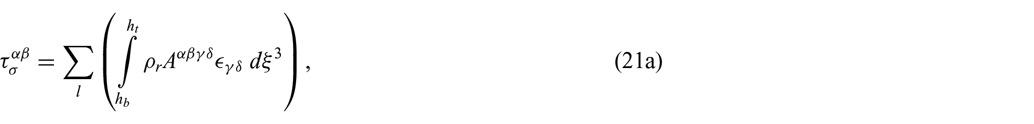
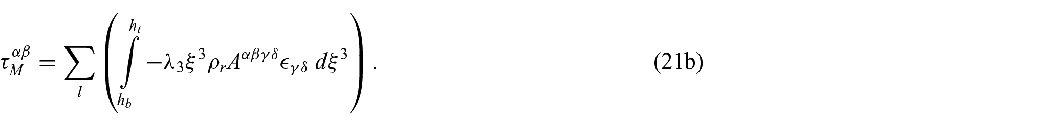
where the subscript denotes the layer number for considering the general multi-layer surface, and and are the top and bottom thickness coordinates of each layer, respectively. Here, it is assumed that the layers are perfectly bonded. The energy model form for depends on the layer as a surface may consist of layers with different materials. As a specific example, the Saint-Venant energy model, which is a quadratic function of the Green–Lagrange strain measuring the difference between the current and stress-free 3D metric tensors, is given with the plane-stress condition (see Appendix 1 for detailed derivation) by
with the elasticity tensor and , in which and are Lamé constants using Young’s modulus and Poisson’s ratio of the initial body. Here, the subscript of denotes that this Lamé constant is a modified one based on the plane-stress condition from which the thickness-direction strain is given for the Saint-Venant model by , which results in the modification of the Lamé constant, where the original one is . Note that the modified Lamé constant differs from this original one for common values of , that is, between 0.3 and 0.5. Then, the constitutive equations for the resultant mid-surface stresses (19) are obtained as
4. Equivalent monolayer system
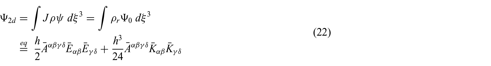
Many thin-shell structures that are actuated by non-mechanical stimuli comprise multiple thin layers, such as the layered aorta growth [128], the pH- or thermo-responsive hydrogel actuators [129, 130], and the bio-inspired nanofiber vascular graft [131]. As differential non-mechanical stimuli induce a change in the rest length, that is, natural stretch, and curvature, that is, natural curvature, of the surface’s mid-surface, we model such multi-layer structures through an equivalent monolayer shell model. Furthermore, we demonstrate how the effects of non-mechanical stimuli, which can be measured experimentally or calculated theoretically, can be accounted for through fundamental forms and of the mid-surface in the rest state. To accomplish this, we adopt a conceptual stress-free (rest) mid-surface, which we call the natural mid-surface, to represent the shell energy of general multi-layer surfaces via an equivalent monolayer surface. We define for clarity that overbar symbols, for example, and , represent stress-free values for the equivalent monolayer system, whereas tilde symbols, for example, , represent stress-free values for each layer of the general multi-layer shell system under consideration. The metric and curvature tensors of the natural mid-surface, that is, and , give information about rest length and curvature of the mid-surface so that the equivalent shell energy density, adopting the Koiter energy form [56], can be found based on the deviation between the current and natural mid-surface as
such that, in the absence of mechanical external loads, the potential energy is calculated as with the initial area element , where and are the equivalent membrane and bending strains in this equivalent monolayer shell system, respectively, and the elasticity tensor of the natural mid-surface is
where and are the equivalent Lamé constants. Consequently, the equivalent mid-surface stress resultants are calculated as
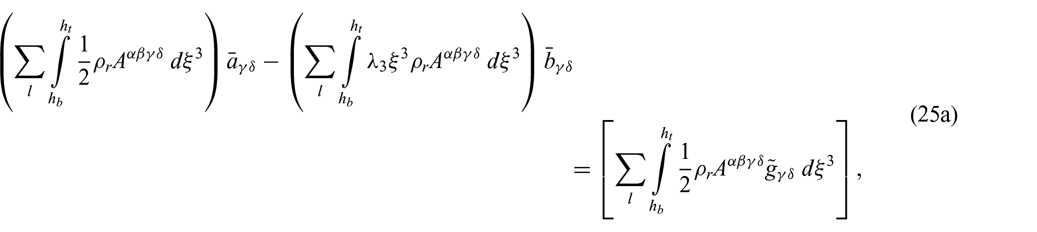
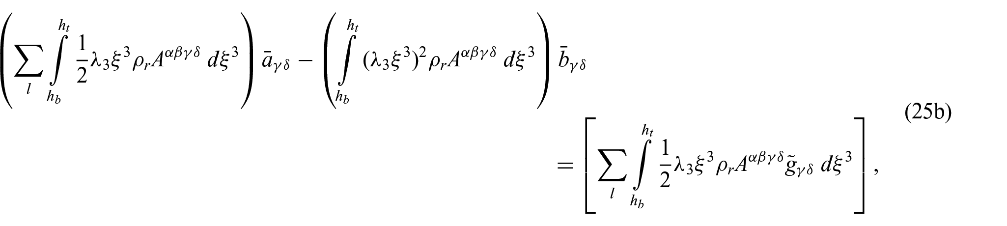
In general, the stimulus profile may be non-homogeneous over the entire body, which requires that the change in rest length and curvature appears as a second-order tensor, so each component of the natural fundamental forms, that is, and , should be, respectively, evaluated according to the stimulus type and profile. To solve for the unknown quantities on the natural mid-surface, that is, fundamental forms and , we build on its physical meaning that the stress resultants vanish at and . While imposing this condition gives a trivial result for equation (24), if used in equation (19), with the Saint-Venant energy model of equation (21), this leads to the following system of equations as
resulting in a system of six equations and six unknowns, from which the fundamental forms of the natural mid-surface (i.e. the three components for each of and ) can be obtained relying on that fundamental forms of the mid-surface are symmetric.
Equation (25) is an important result because it enables a direct linkage between the natural fundamental forms and the layer’s stress-free 3D metric tensor , which can be experimentally measured or theoretically calculated for the non-mechanical stimuli under consideration. Therefore, from the prescribed stress-free 3D metric tensor of each layer for the general multi-layer surface, the fundamental forms and of the natural mid-surface, which govern the deformation of the equivalent monolayer shell system, can be obtained using equation (25).
For the special case where the non-mechanical stimulus homogeneously acts on some segment of the shell, the natural mid-surface can be represented by scalar values of (natural stretch) and (natural curvature) as and [48, 99, 113], which enables a simpler system of equations from equation (25) and which may lead to explicit forms of the natural stretch and curvature in some cases. For example, if initially flat bilayer surfaces with thickness undergo an isotropic area expansion as with expansion factor that varies as a function of the thickness but remains homogeneous within each layer, the stress-free 3D metric tensor can be expressed as for the upper layer (i.e. denoted by subscript 1) and for the lower layer (i.e. denoted by subscript 2), with the initial 3D metric tensor using the initial mid-surface fundamental forms and . Substituting these stress-free metric tensors into the simpler system of equations from equation (25), analytical equations for and can be derived under the assumption that each layer has similar Poisson’s ratio with an assumption of small thickness change as
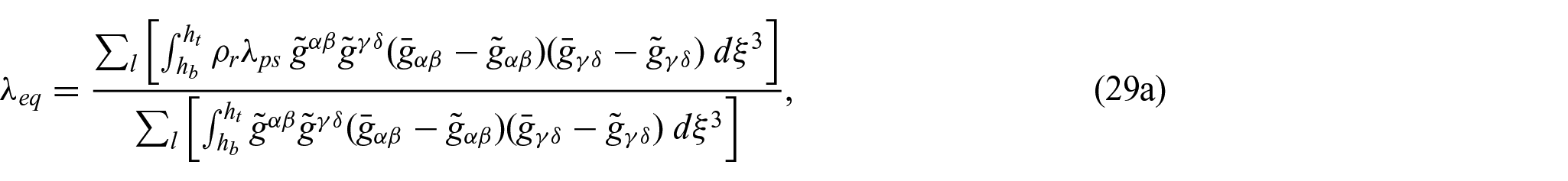
where subscripts 1 and 2 denote the upper and lower layer, respectively, is the thickness ratio, and is the modulus ratio. A few equations for the scalar natural quantities have been proposed, for example, Pezzulla et al. [99] via the linear geometrical projection and Lucantonio et al. [132] via one-dimensional (1D) beam theory. However, both Pezzulla et al. [99] and Lucantonio et al. [132] did not consider the multidimensional features of shells as well as the mass change effect from biological growth.
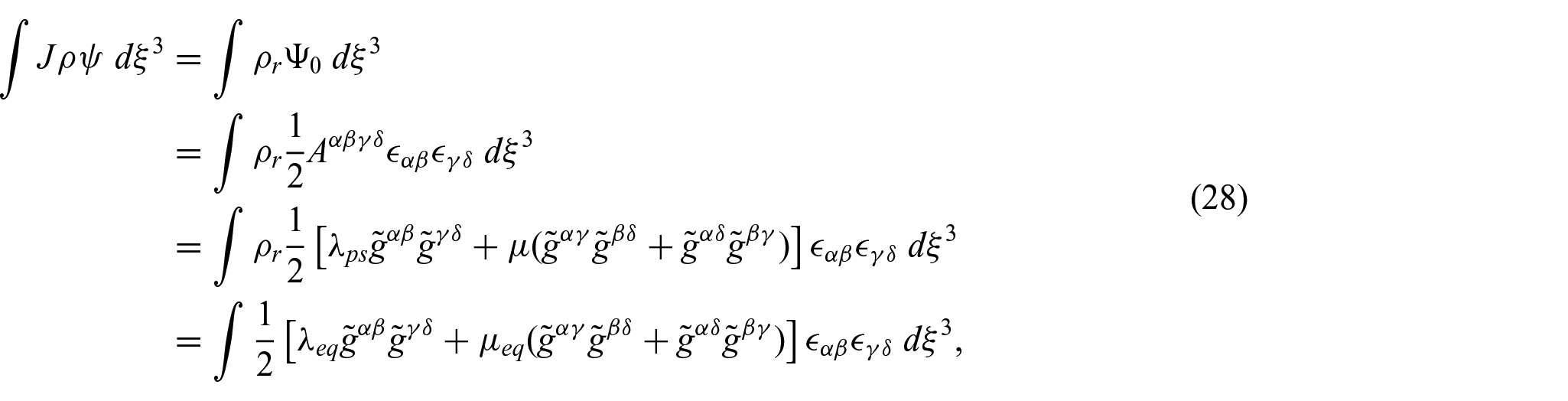
As and effectively represent the material properties of a general multi-layer surface, one can easily derive those values via its definition for the Saint-Venant energy model with the plane-stress condition as
which shows the equivalent Lamé constants encompass the different material properties and the effect of mass addition in terms of biological growth via the density ratio . Then, the equivalent Lamé constants can be calculated as
with higher order terms neglected, in which as following the Kirchhoff–Love shell kinematics. Note that for the special case where the actual surface is composed of a single layer, that is, , the equivalent Lamé constants are and . The mass increase during growth implies that more energy is needed to make a body deform as it grows, which is clearly captured by the appearance of the stress amplification factor in the equivalent Lamé constants.
5. Stimuli-responsive shell theory
The previous derivations demonstrate how a multi-layer surface system can be expressed as an equivalent monolayer system with natural fundamental forms and that prescribe how the monolayer shell will deform in response to non-mechanical stimuli. In this section, we will derive the effective strain energy density while accounting for the fundamental forms and will demonstrate how the effects of non-mechanical stimuli can be captured using standard body forces, tractions, and torques that act along the area or perimeter of the shell by treating the initial configuration as a reference stress-free configuration. The resultant weak form then can be solved numerically as a standard mechanical boundary value problem, in which the standard equilibrium equation is solved accounting for the standard internal stresses due to deformations from the initial body and external forces while still accounting for the effects of the non-mechanical stimuli.
We begin by re-expressing the equivalent membrane strain in equation (22) by splitting it as
where equation (30b) is the standard mechanical term, and equation (30c) is the stimulus-induced term. The equivalent bending strain in equation (22) is also re-expressed as
with its standard mechanical term of equation (31b) and stimulus-induced term of equation (31c). Then, inserting these re-expressed strains into equation (22) yields a new form of the shell energy density which is fully decomposed into an internal strain energy term , which depends on the deformation with respect to the initial configuration, and effective external terms in terms of the effect of non-mechanical stimuli, given as
in which we note that has the same form as the standard Koiter shell energy model, which depends on deformations between the current and initial mid-surface [58], with its elasticity tensor , while superscripts and on denote the stretching- and bending-related terms, respectively. Then, we can fully expand the effective external terms via Taylor series about and as
with natural stretch and natural curvature as general tensorial forms for local, non-homogeneous stimuli, which measure the change in the rest length and curvature of the mid-surface under the non-mechanical stimuli, respectively. We note that as these natural stretch and curvature have general tensorial forms, the anisotropic characteristics of non-mechanical stimuli can be represented in this theory, such as orthotropic area expansion of soft tissues containing microfibrils induced by swelling [133, 134]. Here, the first terms on the right-hand side (RHS) of equations (33a) and (33b) will not affect the variation of shell energy because they are independent of displacement. Furthermore, in the third terms on the RHS of equations (33a) and (33b), the deviation of elasticity tensors introduces a change in the energy of , which corresponds to the difference in the metric tensors in the natural state and the undeformed, initial state , that is, where is the largest principal extension in the stress-free state from the initial body. In this paper, we will thus neglect the first terms and the third terms associated with the deviation that comes from , as a similar deviation between the fundamental (equilibrium) and initial configuration is ignored in standard continuum mechanics [135], allowing us to finally write the effective external terms of the shell energy density as
In this final form of the effective external terms for the effect of non-mechanical stimuli, the variable is the displacement in the current metric and curvature tensor ( and ), while the natural fundamental forms ( and ) are the free input parameters that can be calculated through equation (25) using any available experimental and/or theoretical data that describe how each layer of general multi-layer surface responds to the non-mechanical stimuli. Therefore, we have established a relationship between the effect of non-mechanical stimuli, such as its intensity and direction that are characterized from experimental measurements or theoretical calculation, and displacement, which is similar to the standard work-conjugate relationship between displacement and mechanical loads.
5.1. Variational approach
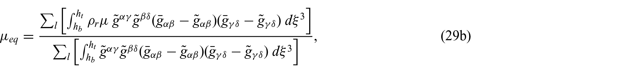
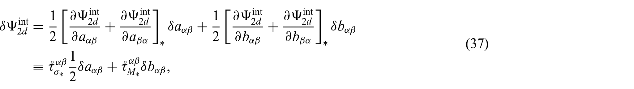
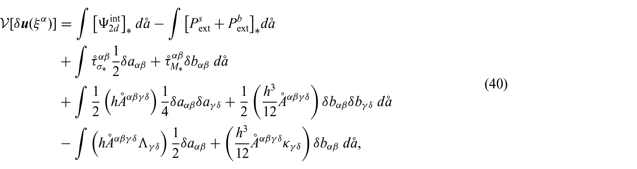
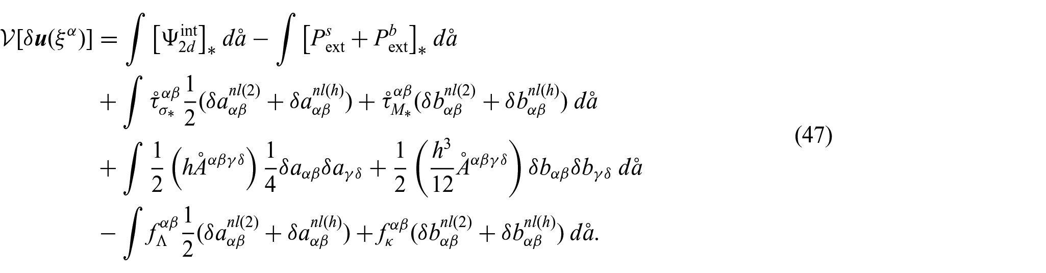
Having established the novel SRS energy density of equation (32a) with the internal term (32b) and effective external terms (34), we now derive the first and second variations of the potential energy. These are essential for understanding how the non-mechanical stimuli work on the body and enabling a numerical (i.e. finite element-based) solution to boundary value problems (first variation) and also for enabling examinations into the stability of the shells subject to the non-mechanical stimuli (second variation). To do so, we will closely follow the mathematical treatment by Koiter and Van Der Heijden [135], and Thompson and Hunt [136, 137] by starting with equations (32b) and (34) to obtain integral formulations in terms of the equilibrium equation and the stability criteria. For this novel SRS theory, the functional of mechanical potential energy is calculated as
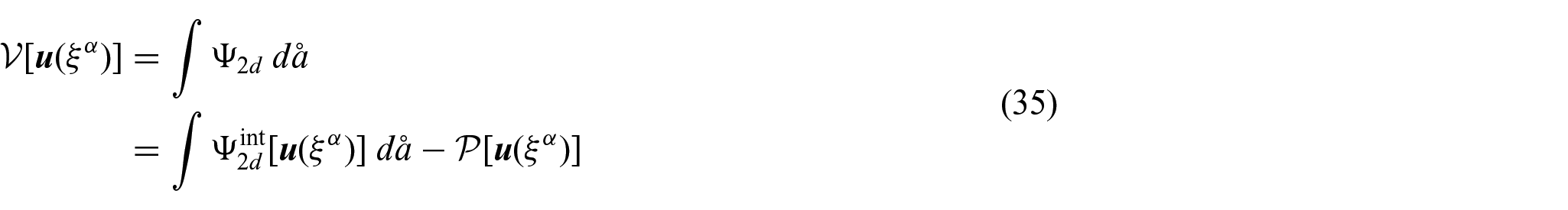
in which the total potential energy is the internal strain energy using equation (32b) minus the external potential using equation (34) in , where is the displacement vector between the current and initial configurations, and is the area element of the initial shell with the in-plane coordinates and . We will investigate a shell that is in a state of equilibrium by expanding each term in this energy functional via Taylor series about the metric and curvature tensors at the fundamental (equilibrium) state. Then, we find the energy density in the internal strain energy as
where and are the variation in the metric and curvature tensor, respectively, with the superscript and subscript (*) denoting a quantity related to the fundamental state here and hereafter in this section. The second and third terms on the RHS can be further examined by virtue of the variation with the stress constitution as
where the symmetric mid-surface membrane and bending stresses, in which the initial configuration is the stress-free configuration, are introduced, that is,
Next, we can also expand the integrand of the external potential as
Now, we write the functional of mechanical potential energy as
where is the variation in displacement vector (i.e. a change between the current and fundamental configurations) such that and are functions of . For convenience, we introduce and whose superscripts , , and denote the first-order (linear), second-order, and higher-order terms with respect to the displacement , respectively.
Since the fundamental state for our investigation is an equilibrium state, the first-order part of the energy functional with respect to the displacement variation , called first variation of energy functional, must be stationary for all admissible displacement fields. As the first variation only contains the linear terms in of equation (40), this leads to
where is the first variation of energy functional with superscript 1 denoting the linear-order part with respect to , with
Equation (41) represents the balance of linear momentum in the integral form.
Now, we will further manipulate equation (41) to explicitly determine how the non-mechanical stimuli act to deform the shell. If we denote the displacement field , that is, the in-plane displacement and the normal displacement , we can approximate [126]
where is the covariant derivative with respect to the initial configuration. Here and hereafter in this section, we use the initial metric tensor to raise and lower indices. Then, inserting equation (43) only into the external potential term, that is, the second integral term of equation (41), and using the Stokes theorem give
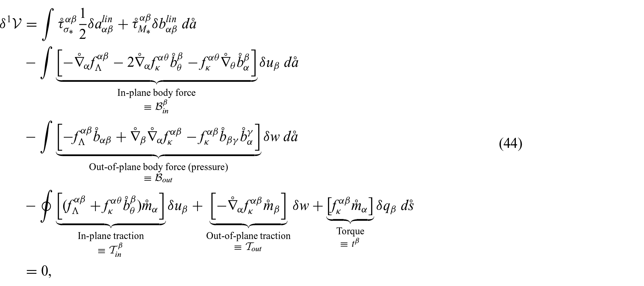
where is the unit normal vector to the initial boundary curve, and is the initial boundary curve element. Here, the rotation vector is used such that [126].
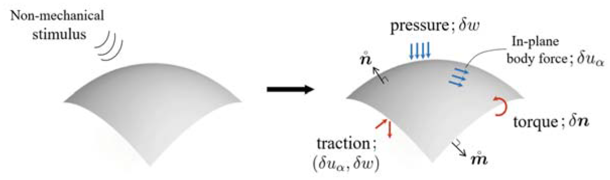
Equation (44) shows how the non-mechanical stimuli, which change the rest length and curvature of the mid-surface via and , act to deform the shell. Specifically, non-mechanical stimuli do not impact the internal potential energy (the first line of the RHS in equation (44)). Instead, the non-mechanical stimuli act as effective external loads to deform the initial, undeformed body as the external terms are functions of the shell displacements and their derivatives (the second, third, and fourth lines of the RHS in equation (44)). Then, based on the well-known mechanical work conjugates, we can see that the effect of non-mechanical stimuli plays a similar role as mechanical, external loadings do in classical mechanics as shown in Figure 2—for body forces, in-plane body force (conjugated with ) and out-of-plane body force (conjugated with ), that is, pressure; for boundary loads, in-plane traction (conjugated with ), out-of-plane traction (conjugated with ), and torque (conjugated with ).
Transformation of the effect of non-mechanical stimulus into effective external loads according to the mechanical work conjugates. Blue arrows denote that those are body force-type effective loads, while red arrows mean boundary forces and torque.
Furthermore, the weak form of equation (44) can be utilized as the starting point to use well-established numerical techniques, such as the finite element method, to solve mechanical boundary value problems where all external loads, due to either mechanical loads or non-mechanical stimuli, are applied as standard mechanical, external loadings. We do note that the finite element approaches for the shell analysis must satisfy at least continuity of the shape functions due to the presence of the second derivative in the curvature tensor. However, this offers the distinct advantage that mechanicians and non-mechanicians alike can easily modify existing computational tools with additional external forces to study how various types of non-mechanical stimuli impact the mechanics and physics of thin-shell structures.
In addition, inserting equation (43) into both integral terms in equation (41) and using the Stokes theorem give the Euler–Lagrange equations as
with boundary conditions as
These equations and boundary conditions of equations (45) and (46) form a boundary value problem. Note that equations (45a), (46a), and (46b) have a free index of as vector forms, while equations (45b) and (46c) are scalar forms.
Then, accounting for equation (41), the functional of mechanical potential energy becomes
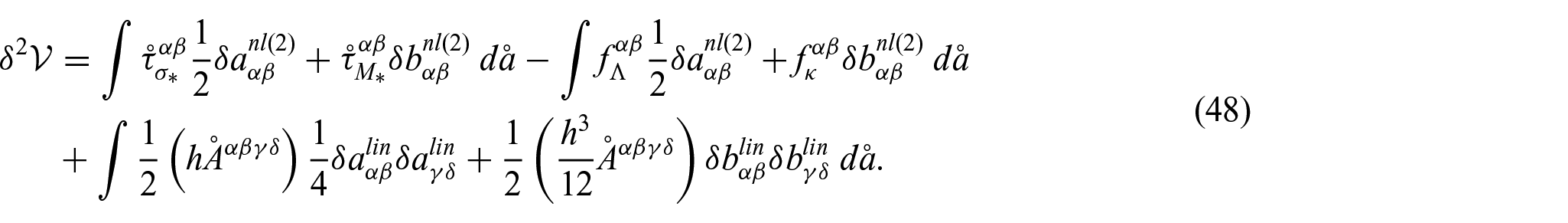
The equilibrium state is stable if the functional of mechanical potential energy is positive definite, which can be tested via the character of the second-order part in the energy functional with respect to the displacement variation , called second variation of energy functional, that is, with denoting the second variation [135–137]. By virtue of variational calculus, the second variation only contains the second-order terms in , which correspond to terms containing and as well as the linear terms in the product and , that is, and , as
Therefore, the stability of the stimuli-responsive shells under investigation can be determined by the character of equation (48).
6. Validation
In this section, the performance of the proposed SRS theory is illustrated by several benchmark problems under plane-strain conditions, considering different types of stimuli and their corresponding impact on the natural stretch and curvature of shells. As the natural fundamental forms and are prescribed, the shell deformations are obtained analytically as well as numerically using the derived weak form (44) with the isogeometric analysis (IGA), which is a modern finite element method well-suited for shell problems due to its shape function’s higher continuity [138], and verified by available reference solutions. Details of the IGA formulation, including discretization of the weak form, can be found in Appendix 3.
6.1. Plates
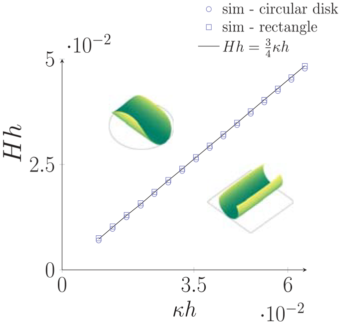
During differential swelling [101] and growth [113] of thin shells, these non-mechanical stimuli can induce isotropic area expansion that is homogeneous in the in-plane direction but varies in the thickness direction. This results in a change in not only the rest length (natural stretch) but also the rest curvature (natural stretch) in the mid-surface. These changes can be represented by scalar values of and via and as stated in Section 4. If considering the action of the scalar natural stretch and curvature on plates with thickness , it has been shown that the resulting deformation is bending-dominant and that the plates bend into cylindrical shapes with Germain (mean) curvature , which can be found analytically for incompressible plates as [48, 99]
which indicates that the mean curvature change is solely due to the natural curvature. Thus, we shall test our proposed SRS theory under pure natural curvature based on this plate problem.
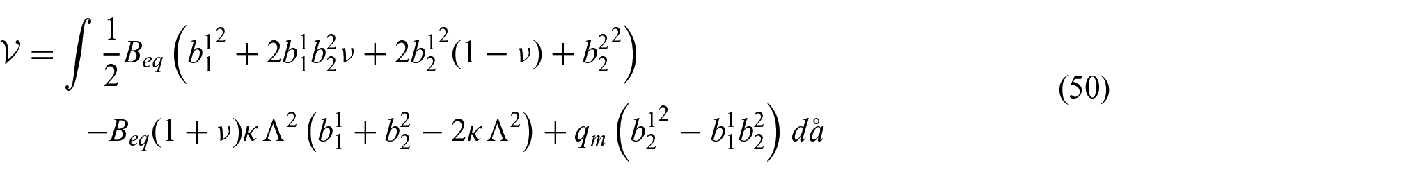
By first recalling that the shell deformation is dominated by bending because the shells are thin, we can analytically obtain the mean curvature by minimizing the bending-related parts in the mechanical potential energy of equation (35) by assuming that the stretching-related terms vanish as , meaning the shell deformation is entirely due to bending. Then, since the Gauss–Codazzi–Mainardi equations for the surface constraint admit homogeneous second fundamental forms for a flat homogeneous metric, the solution can be calculated by minimizing the bending-related parts with a constraint on the null Gaussian curvature via a Lagrange multiplier. As aforementioned, the homogeneous natural quantities allow us to use and , and inserting these relations with for plates into equation (35) gives its mechanical potential energy as
with and the bending rigidity , in which is the Lagrange multiplier to impose the constraint of the null Gaussian curvature. Here, we assume that Poisson’s ratio is homogeneous in the body. If we denote the integrand of this equation as , since all variables in the integrand are homogeneous, the solution of minimum potential energy can be simply obtained via , which gives
in which both solutions have dimensionless mean curvature for incompressible materials, which is consistent with the previous work of equation (49), while also matching our simulation results with MPa and as shown in Figure 3.
Change in mean curvature of an incompressible plate as a function of natural curvature. Symbols denote IGA simulation results obtained via the proposed stimuli-responsive shell theory based on equation (44), while the solid line is the analytical solution of equation (49) for which our proposed theory gives the same solution as the previous works [48, 99].
6.2. Cylinders
The previous example for flat plates considered a scalar natural stretch and curvature that are induced by a stimulus like differential swelling in the thickness direction [99, 139], which results in area expansion that is isotropic in-plane but varies in the thickness direction. In contrast, cylinders have an initial curvature, and as a result, a different deformation feature is observed for the same stimulus profile. Cylinders unroll and snap like a tape-spring, or “snap bracelet” [140], when exposed to curvature stimulus whose sign is the opposite of its initial curvature. This bending-dominant deformation of the cylinder with radius and thickness has been well studied in Pezzulla et al. [99] where the deformed mean curvature is analytically solved as
in which is the critical natural curvature when the cylinder curvature changes sign. In this case, both the natural stretch and curvature appear to affect the mean curvature change during the deformation. However, it has been shown that the thickness-dependent stimulus results in minimal stretching of the shell’s mid-surface [51], so the effect of natural stretching is weak during the cylinder deformation, that is, . Thus, we shall test our proposed novel SRS theory under a combination of natural curvature and weak stretching based on this cylinder problem. This problem also demonstrates the applicability of our proposed theory for the initially curved geometry and its ability to capture the deformation preference for a bi-stable problem [99].
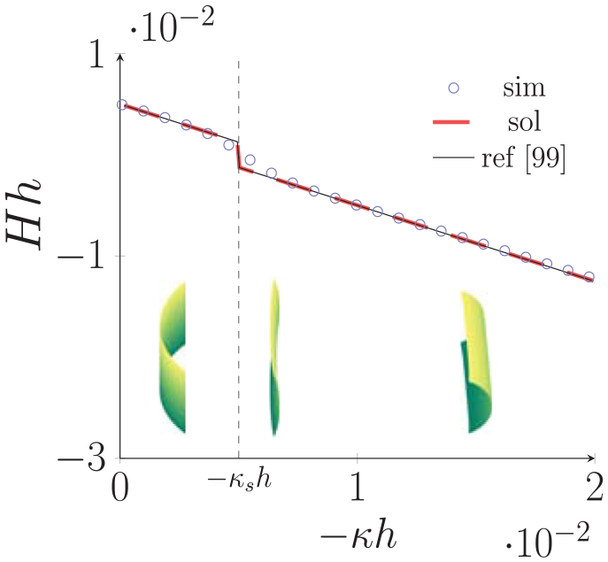
Our numerical solutions via the proposed SRS theory accurately capture the evolution of the dimensionless mean curvature as well as the critical point of the sign change of curvature as shown in Figure 4. In addition, the critical point is analytically evaluated through the proposed shell theory. As in the above plate problem, for thin cylindrical shells, the shell’s bending-dominated deformation in which the stretching-related parts of the potential energy vanish, that is, , leads to homogeneous second fundamental forms for the zero Gaussian curvature of initial cylinder shapes. Then, we have for initial cylindrical shapes with a cylindrical coordinate system
which gives the mechanical potential energy of equation (35) using and by assuming a homogeneous Poisson’s ratio as
with . Since the integrand of this equation only includes homogeneous variables like the above plate problem, the solution of minimum potential energy is obtained via as
Change in mean curvature of an incompressible cylinder due to natural stretch and curvature, with the critical transition point of equation (56), which is analytically obtained via the proposed SRS theory, denoted using the black vertical dashed line. Symbols denote IGA simulation results obtained via the proposed stimuli-responsive shell theory. The black solid line is the reference analytical solution of equation (52) [99], while the colored dashed line is the analytical solution of equation (57) using the proposed stimuli-responsive shell theory.
As both these solutions provide the stationary states of the cylinder under scalar natural quantities, the cylinder deforms in a way to have smaller potential energy among the two stationary solutions, that is, bi-stable state—one keeps the original bending orientation, while the other has a rotated configuration. Hence, inserting these two solutions into equation (54) gives two energies corresponding to a deformed shape with the original bending direction and the rotated one after snapping, and equating those two energies gives the transition point at which the cylinder switches its bending orientation with the critical natural curvature as
Then, the dimensionless mean curvature is analytically obtained as
Here, an error of exists between the previous work of equation (52) and the analytical solutions of equation (57) obtained via the proposed SRS theory. This error comes from the fact that the solution obtained by the proposed theory stems from the natural curvature tensor written as , while the previous work of equation (52) utilized for their solution. For the isotropic area expansion induced by non-mechanical stimuli, the correct expression is the one used in our solution. However, the natural curvature for thin bodies undergoing differential stimulus through the thickness direction will barely or not stretch the shell’s mid-surface [51], so this error is negligible. Therefore, the analytical solutions via our proposed novel SRS theory have good agreement with the previous work as shown in Figure 4.
6.3. Annulus
The purpose of this verification example is to both examine the performance of the proposed SRS theory for a stretching-dominated problem and demonstrate the ability to examine the onset of buckling instability through a linear stability analysis. When a monolayer plate annulus with radius and thickness is subject to an inhomogeneous stimulus profile such that the natural metric tensor has a spherical form with the radial distance from the center as
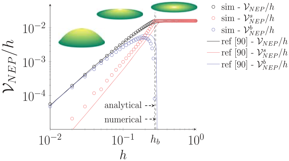
along with a flat natural curvature tensor, the circular plate annulus remains flat for thicknesses above a critical value for a buckling transition (), while the plate buckled into a spherical shape for thicknesses below the critical buckling transition. Numerical solutions to this problem were obtained by employing the NEP theory that involves minimizing the following potential energy [90]:
in which is the elasticity tensor for NEP theory, and is the area element of a conceptually stress-free plate.
While the integrand in the potential energy (59) of the NEP theory is similar to our equivalent monolayer shell model with equation (22) using the natural fundamental forms and , there are several key differences. First, the potential energy of the NEP theory is obtained through integration over the conceptual stress-free configuration as can be seen in equation (59), which implies that for a total Lagrangian formulation, the resultant mid-surface stresses of this theory have a pre-factor as and . This pre-factor always exists regardless of the stimulus type, which may be incorrect as we discussed in Section 3 in terms of the mass change effect. In contrast, our equivalent monolayer shell model utilizes the equivalent material properties that account for the effect of mass addition in terms of biological growth on the stress constitution, such that the stiffness difference between the stimulus types with respect to the mass addition can be described. Second, while our proposed theory utilizes the initial configuration as a stress-free state, the NEP potential energy is formulated using the fictitious configuration as its stress-free state, and this makes it hard to derive physical interpretations of the role of non-mechanical stimuli in mechanical deformations and instabilities. Moreover, since the integration of potential energy in the NEP theory and its elasticity tensor are based on the natural metric tensor , interpretation of stress states and a linear stability analysis with the NEP theory are challenging even if the natural metric tensor has a simple form.
Based on the NEP theory and assuming axisymmetry, the value of the buckling transition was numerically found to be for incompressible materials when and the annulus geometry was and [90]. Here, we will test our SRS theory under pure natural stretch based on this annulus problem, for both the performance of the proposed novel SRS theory and its ability to examine the onset of buckling instability through a linear stability analysis.
We solve this problem via our proposed novel SRS theory by inserting the prescribed natural fundamental forms of equation (58) and in equation (44). Our numerical solutions give the value of buckling transition as , which is in good agreement with the previous work. In addition, comparing the energies of equation (59) using the deformation solutions obtained via our proposed SRS theory, it is clear that the proposed theory accurately captures the evolution of all energies depending on the deformation as shown in Figure 5.
Furthermore, the solution of the membrane and bending stresses can be analytically obtained by solving equation (45) with equation (46) under axisymmetric conditions using the polar coordinate system relying on the initial geometry as
with the stretching rigidity , where is the radial coordinate, and is the sine cardinal function. Here, as the annulus is a monolayer surface, we denote Poisson’s ratio in equation (60) without the subscript while keeping it on the membrane rigidity for the sake of generality in terms of the effect of mass addition (i.e. for stimulus types without mass addition, also). We approximate the buckled shape by assuming that the components of have forms as
where is a constant real number and is an integer. Then, the Donnell–Mushtari–Vlasov theory leads to the linear and second-order terms of the variations and [126] as
such that the resulting balance equation obtained via the first variation of equation (48) with the integration domain and leads to the buckling transition thickness with as which agrees well with both our numerical result and the previous NEP-based work.
Annulus disk under in-plane differential natural stretch. is the stretching energy part of the first term in equation (59), whereas is the bending energy part of the second term. Symbols denote IGA simulation results obtained via the proposed stimuli-responsive shell theory, while solid lines mean the reference numerical solutions in Efrati et al. [90]. Vertical dashed lines at denote the buckling transition thickness obtained by the proposed stimuli-responsive shell theory.
The assumption of axisymmetry in this problem is made for the purpose of validation as the reference solution of Efrati et al. [90] artificially requires the axisymmetric constraint; however, we note that our numerics indicate that if the axisymmetric constraint is relaxed, the dome-like shape is no longer observed below a critical thickness.
7. Examples
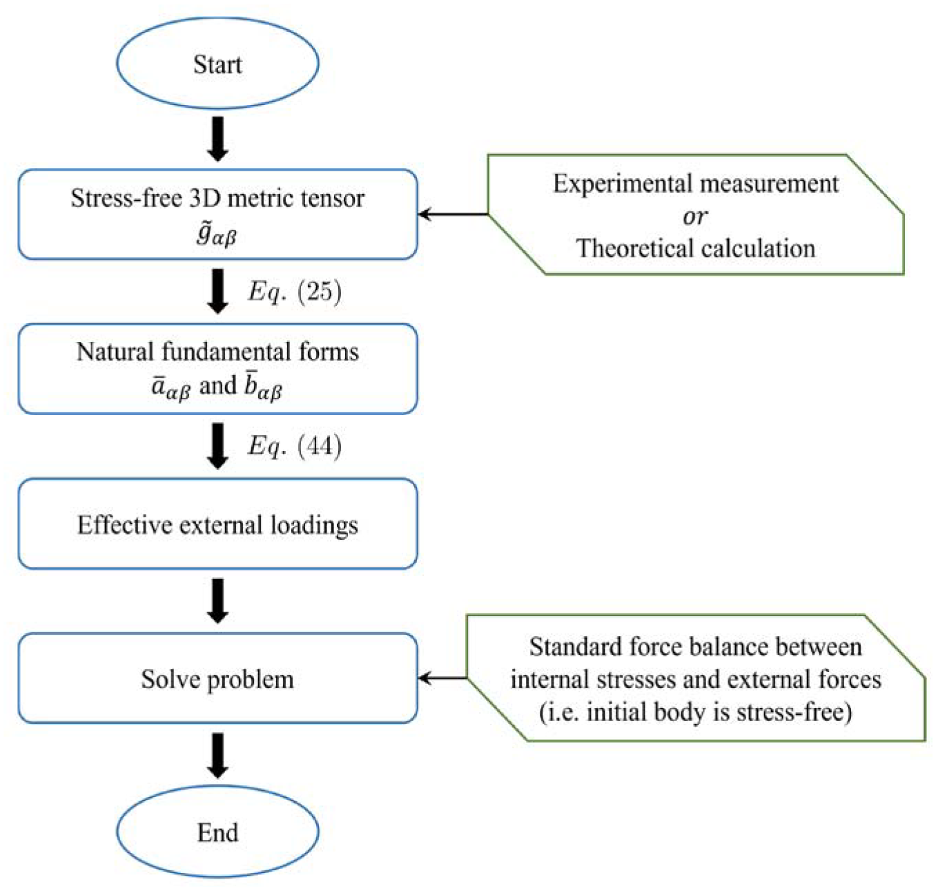
In the previous section, we validated the proposed SRS theory and demonstrated that the effective external terms representing the effects of non-mechanical stimuli on deformation can capture fundamental cases involving either stretching or curvature (bending) dominated deformations. In this section, we apply the SRS theory to more complex examples considering shape changes induced by various types of stimuli, including biological growth, swelling, and applied electric voltage. One key goal of this section is to demonstrate how, using experimentally measured data for shells deformed by non-mechanical stimuli, we can obtain the corresponding stress-free 3D metric tensor of each layer, and thus the specific forms of the natural fundamental forms and to determine the resulting effective external loadings that deform the body. This solution process is shown in the flowchart in Figure 6.
Flowchart for the process to obtain effective external loadings induced by non-mechanical stimuli, based on experimentally measured or theoretically calculated data. These external loadings can then be used to solve deformation problems via the proposed stimuli-responsive shell theory.
7.1. Long leaf growth
In the first example problem, we consider the biological growth of long leaves. We obtain numerical and analytical predictions of the shape-morphing process through the SRS theory and demonstrate the ability to capture large shape changes resulting from geometric nonlinearity. Morphogenesis in plants is primarily driven by non-homogeneous growth of tissues. Especially for long leaves, which are thin, the role of excessive cell growth within their marginal region is dominant in the shape formation in leaves. Here, we focus on the helical growth that can be commonly seen in nature, such as Dendrobium helix and Prosthechea cochleata.
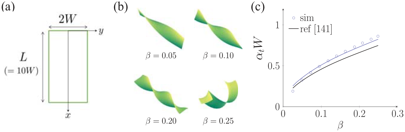
Because helical growth is induced by twisting during growth, we impose a non-homogeneous growth stimulus on a monolayer thin leaf of dimensions cm and cm with thickness (see Figure 7(a)) by implementing a width-direction differential expansion on the leaf, with its material properties of kPa and [141]. To obtain the amount of expansion induced by growth, we follow a previous work [141] that experimentally measured the width-direction differential expansion by dissecting the twisting croton mammy of Codiaeum variegatum leaf into several length-direction strips, in which the length change after the dissection was measured as the functional form where is the strip length after the dissection and provides the maximum growth value. Therefore, the twisting leaf growth is modeled with the experimentally derived expansion factor , based on the concept of expansion factor , via an isotropic area expansion induced by growth as
which is plugged into equations (25) and (29) to calculate the natural fundamental forms and material properties. Here, we account for mass change from growth and its effect on the internal stress by considering the leaf growth as density-preserving in which the newly added mass during growth has the same material properties as the existing material, that is, as discussed in Section 3. Then, we numerically solve equation (44) based on the calculated natural fundamental forms and material properties. The current approach thus differs from the previous work, which modeled the leaf growth process as an equivalent thermal expansion problem and did not account for the effect of mass addition during growth [141]. Specifically, the stress amplification due to mass addition induces a higher contrast in the effect of the width-direction differential growth, which eventually leads to more twisted leaf shapes as a result.
Growing long leaf. (a) Initial geometry with length and width . (b) Shape change process as the growth amount increases, from the initial flat shape to twisted and helical shapes. (c) Twist angle per unit length. Symbols denote IGA simulation results obtained by the proposed SRS theory. The blue solid line is the analytical solution of equation (94) via our proposed SRS theory, whereas the black solid line is the analytical solution as in Huang et al. [141] solely from geometrical considerations.
For progressive leaf growth with increasing , the shell exhibits two distinct shape-shifting events as shown in Figure 7(b), showing the ability to capture significant geometric nonlinearity with the proposed SRS theory. First, the leaf morphs from an initially flat shape to one that becomes gradually more twisted. As the amount of growth increases, the twisted leaf shape morphs to the helical shape around , which is consistent with the previous study of Huang et al. [141].
During twisting, the twisting angle per unit length is analytically calculated depending on the amount of growth. Assuming that the deformed shape has the position vector of the twisted shape as , we obtain the current fundamental forms as
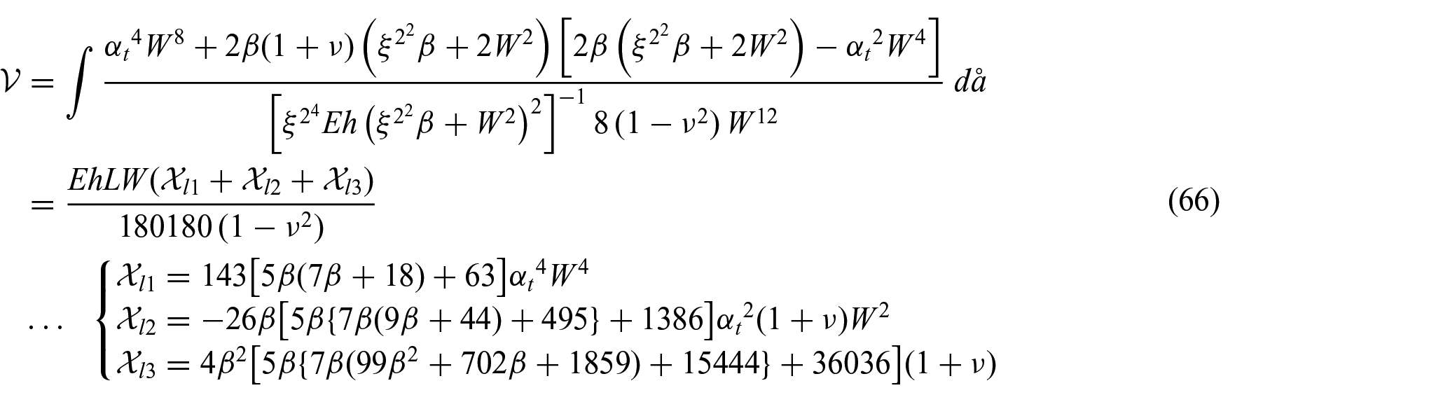
in which , , and is the twisting angle per unit length. Then, inserting the current and natural fundamental forms into equation (35) gives the mechanical potential energy as
with , which leads to the minimum potential energy via with respect to the twisting angle per unit length as
This analytical solution agrees well with the numerical simulation results as shown in Figure 7(c). Note that our analytical equation for the twisting angle via the proposed SRS theory gives similar results to the one proposed of in Huang et al. [141], in which the best fit of Huang et al. [141] compared to equation (67) occurs for since the previous work derived the proposed equation solely from geometric considerations, while our solution is obtained via full elasticity with material properties.
7.2. Swelling-induced closure of Venus flytrap
For our next example, we examine the ability to capture the effects of a different stimulus, that is, swelling, using the proposed SRS theory. Specifically, we examine the swelling-induced closure of a flytrap, which also demonstrates that our proposed theory can accurately capture elastic instabilities that are exploited in nature to realize rapid motion and shape changes. A plant’s leaf blades or flower petals are mainly composed of mesophyll cells sandwiched between two epidermis layers. The differential expansion between the cells on the two different sides of the leaf blades in response to non-mechanical stimuli such as light and humidity dictates the opening and closure of plant tissues. Whereas the flower petal can open only once, many insectivorous plants including the Venus flytrap can repeatedly open and close their leaves during their lifetime. Furthermore, the leaf closure occurs rapidly via snap-through instability induced by differential swelling. Importantly, as we detail below, we model the snap-through process using experimentally-measured data [134] for the differential expansion (induced by swelling) occurring on opposite sides of the flytrap leaves to determine the resulting natural stretch and curvature that the flytrap leaves are subject to. This is in contrast to previous studies [133] where only the natural curvature is prescribed without linkage between the natural curvature and actual response in flytrap leaves to swelling.
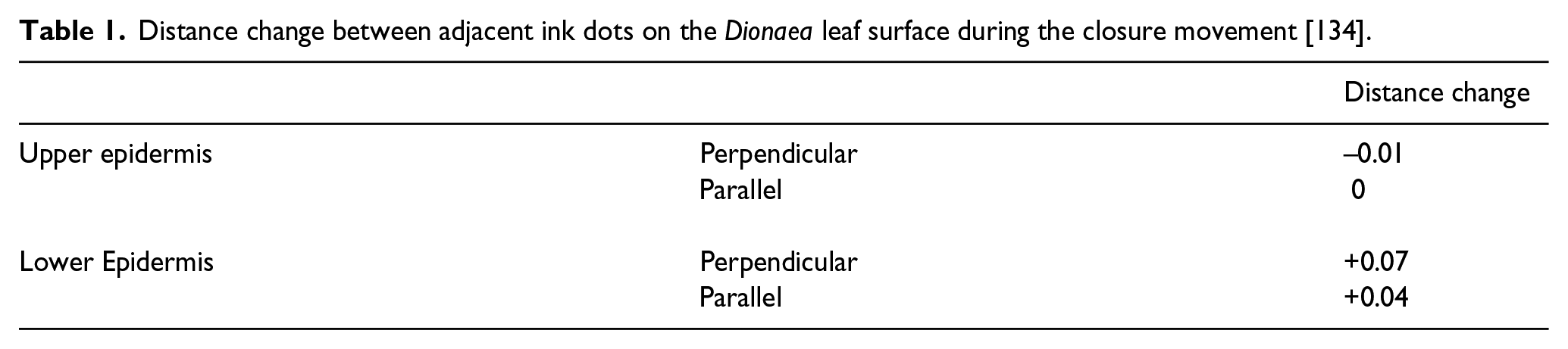
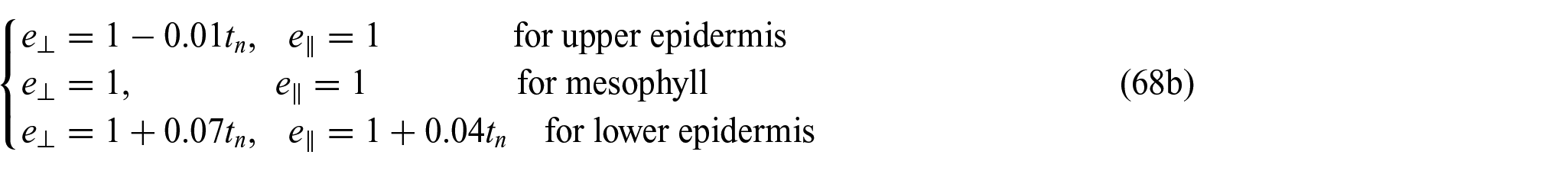
In the cross-sectional cut perpendicular to the midrib of the flytrap leaves, the presence of microfibrils running perpendicular to the midrib has been observed in the upper epidermis. Due to the reinforcement of the cell wall by the microfibrils, the expansion of the upper side of flytrap induced by a stimulus is prevented during the flytrap leaf movement. Following this, a biological experiment was carried out to obtain the expansion factor for the upper and lower sides of the flytrap leaf during the closure movement, for the directions parallel and perpendicular to the midrib [134]. In this experiment, ink dots were drawn on the uppermost and lowermost superficial surfaces of flytrap leaves, and the distance change between ink dots during the closure movement was measured as , where and are the distance between ink dots before and after the closure movement, respectively, as listed in Table 1 [134].
Distance change between adjacent ink dots on the Dionaea leaf surface during the closure movement [134].
Distance change
Upper epidermis
Perpendicular
–0.01
Parallel
0
Lower Epidermis
Perpendicular
+0.07
Parallel
+0.04
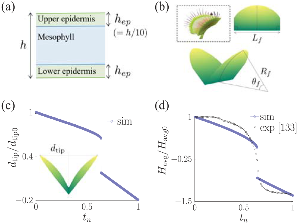
Building on the experimentally observed data, we imposed the thickness-direction differential swelling on a tri-layer surface of thickness , consisting of the mesophyll and the upper and lower epidermis of thickness as shown in Figure 8(a), to mimic the flytrap closure using an orthotropic area expansion induced by swelling as
Snapping-induced closure of flytrap. (a) Trilayer surface of the flytrap leaf. (b) Barrel-like initial shape of the flytrap model with mm, cm, cm, and . (c) IGA simulation results of the change in distance between two tips of the flytrap leaves normalized by its initial value . (d) Average mean curvature normalized by its initial value , compared with experimental data in Forterre et al. [133].
Each layer is allowed different expansion factors ( and ) in the perpendicular and parallel directions to the midrib, where the expansion factor for each layer is prescribed based on the experimentally measured distance changes listed in Table 1 as
in which is the normalization of time with respect to the experimentally observed flytrap closure time s [133]. Here, we assume that the uppermost and lowermost superficial surfaces are almost stress-free so that the experimental data of Table 1 can represent the stress-free 3D metric tensor of each upper and lower layer. Thus, these expansion factors in the perpendicular and parallel direction are plugged into equations (25) and (29) to calculate the natural fundamental forms and material properties and then to numerically solve equation (44). As the type of non-mechanical stimulus is swelling, there is no effect of added mass in this case, i.e., which can also be interpreted by considering that the fluid flowing through the body during swelling does not have mechanical stiffness. As we simplify the initial geometry of flytrap using a barrel-like shape like the actual flytrap leaves as shown in Figure 8(b), with MPa and for all layers [133], our simulation results show that the swelling-induced flytrap closure indeed occurs as a fast leaf movement via snapping as shown in Figure 8(c). Because we are able to capture the experimentally measured timescale and change in mean curvature as shown in Figure 8(d), this indicates our SRS theory can accurately capture swelling-induced snapping of plant leaves.
7.3. Voltage-induced buckling of dielectric film
Our final example demonstrates the ability of the proposed novel SRS theory to capture a different stimulus, that is, the electric field–induced actuation of thin structures, including predicting the onset of electromechanical instabilities via a stability analysis. As the dielectric elastomer is composed of a film, which is electrically insulated and can be polarized via applying an electric field, between two electrodes, a Maxwell stress is developed in the film to the surface normal direction as the electrodes approach each other under an applied electric field [142, 143]. During this process, the film isotropically expands in the in-plane direction due to the repulsion of like charges along each surface of the film, which generates significant natural stretching, which motivates the application of the proposed novel SRS theory for this problem. Clamping the film generates compressive stresses by preventing the film from expanding in-plane, which leads to buckling of the film when the compressive stress exceeds a critical value. This buckling of dielectric elastomer has been used to pump fluids within microfluidic systems in response to an applied electric field as the dielectric elastomer can be actively and reversely buckled out of plane [19–20]. To enhance the functionality of microfluidic systems, controlling and directing fluid flow are essential [144–146]. Thus, estimation of the critical voltage that induces the critical compressive stress is crucial to predicting the onset of instabilities for the dielectric elastomer within microfluidic and other systems.
Our analysis of this problem is thus motivated by the significant natural stretching that occurs, and also because while the estimation of the critical voltage has been widely studied using standard solid continuum models [19, 20, 147, 148], the estimation of the critical buckling voltage has not, to the best of our knowledge, been derived based on a shell theory. Furthermore, we demonstrate the ability to analyze the stability of complex multi-physics phenomena using the natural stretch- and curvature-based SRS theory, in which the natural stretch for this problem is obtained from a theoretically calculated expansion factor based on the Maxwell stress. Since the buckling of dielectric elastomers occurs due to the developing compressive stress in the film, we focus on the positive-definite characteristic of the second variation (48) of the film’s mechanical potential energy.
The expansion factor depending on the applied voltage can be theoretically calculated using the Maxwell stress in the dielectric film with thickness , while the Maxwell stress induced by an applied voltage is calculated as , where is the Poisson’s ratio of the film, is the applied voltage, and and are, respectively, the free space permittivity and the relative dielectric constant [142, 149]. When a free-standing dielectric film is isotropically expanding to the in-plane direction while simultaneously reducing its thickness due to an applied voltage, the second Piola–Kirchhoff stress in the film with respect to deformations from the initial body can be calculated using the Saint-Venant energy model [150] as
where and are the Lamé constants of the dielectric film with the film’s Young’s modulus . Since the dielectric film is homogeneously expanding without any constraint, the current 3D metric tensor can be assumed with the expansion factor as
in which has the information about a change in thickness as stated in Section 2. Relying on the definition of Maxwell stress, equating with for the free-standing homogeneous expansion of the film gives the expansion factor that depends on the applied voltage as
The dielectric film geometry is that of a circular plate with radius and thickness . Building on the polar coordinate system of radial and polar coordinates, the solution of stress states on the fundamental (equilibrium) configuration of the clamped film can be calculated via equation (45) with equation (46) using the natural fundamental forms and material properties obtained by plugging
into equations (25) and (29), based on the isotropic area expansion induced by the applied voltage. As the type of non-mechanical stimulus is the voltage, there is no mass addition in this case, that is, . Then, solving equation (45) with equation (46) under clamped boundary conditions, while exploiting the axisymmetry, gives the solution of the membrane and bending stresses in the film caused by the applied voltage as
In this example problem, following Timoshenko’s and Bulson’s [151, 152] works, we solve this stability problem under the fixed boundary condition, and the effect of clamped boundary condition on the buckling is dealt with by employing the compensating factor which is a constant for a clamped plate exhibiting the first-mode buckling, as . Similar to the annulus benchmark problem above, we approximate the buckled shape by assuming that the components of have forms as
where is a constant real number and is an integer. With the Donnell-Mushtari–Vlasov theory of equations (62) and (63), the resulting balance equation obtained via the first variation of equation (48) with the integration domain and leads to the critical voltage for buckling with as
This critical voltage gives kV for incompressible films with MPa, μm, μm, , and N/V2, which is in agreement with the previous work of kV in Tavakol and Holmes [20] that solved this buckling problem using the existing closed-form of critical buckling stresses.
8. Conclusion
We have presented a general shell theory to account for non-mechanical stimuli. We show that regardless of the specific type of stimuli, they can be generalized into three particular forms: those that add mass to the shell, those that increase the area of the shell through the natural stretch , and those that change the curvature of the shell through the natural curvature. Considering these effects, we demonstrated how to form a mechanical interpretation of non-mechanical stimuli, in which the standard shell strain energy can be augmented by a potential corresponding to how a non-mechanical stimulus acts to change the shell’s area and a potential corresponding to a stimulus that acts to change the shell’s curvature. We also generalized the effect of mass added during biological growth on the stress constitution based on a mass balance during the growth process. By developing these potentials, we enable the usage of standard tools for the mechanics community, that is, taking variations to derive a weak form that can be used for finite element analysis and also to use second variations to perform linear stability analyses. The theory is formulated based on a standard, stress-free reference configuration that is known a priori, meaning that it can be physically observed, and only requires the solution of a single-field equation, the standard mechanical momentum or equilibrium equation, despite capturing the effects of non-mechanical stimuli. Furthermore, we derived analytical equations for an equivalent monolayer system to calculate its natural fundamental forms and material properties, which prescribe the shell deformation. For these equations, we can use experimental measurements or theoretical calculations of deformations under various stimuli in general multi-layer surfaces. Overall, we expect that mechanicians and non-mechanicians alike can use the approach presented here to modify existing computational tools with the effective external loadings calculated in this novel theory in order to study how various types of non-mechanical stimuli impact the mechanics and physics of thin-shell structures.
Footnotes
Appendix 1
Appendix 2
Appendix 3
Declaration of conflicting interests
The author(s) declared no potential conflicts of interest with respect to the research, authorship, and/or publication of this article.
Funding
The author(s) disclosed receipt of the following financial support for the research, authorship, and/or publication of this article: J.H.L., H.S.P., and D.P.H gratefully acknowledge the financial support from the National Science Foundation through CMMI-1824882.
ORCID iD
Jeong-Ho Lee
References
1.
MannDLKentRLCooperG4th. Load regulation of the properties of adult feline cardiocytes: growth induction by cellular deformation. Circ Res1989; 64(6): 1079–1090.
2.
MerkelMManningML.Using cell deformation and motion to predict forces and collective behavior in morphogenesis. Semin Cell Dev Biol2017; 67: 161–169.
3.
AdachiTAonumaYItoS, et al. Osteocyte calcium signaling response to bone matrix deformation. J Biomech2009; 42(15): 2507–2512.
4.
KindbergAHuJKBushJO.Forced to communicate: integration of mechanical and biochemical signaling in morphogenesis. Curr Opin Cell Biol2020; 66: 59–68.
5.
HeisenbergCPBellaïcheY.Forces in tissue morphogenesis and patterning. Cell2013; 153(5): 948–962.
6.
PałubickiWKokoszaABurianA.Formal description of plant morphogenesis. J Exp Bot2019; 70(14): 3601–3613.
7.
GjorevskiNNelsonCM.Bidirectional extracellular matrix signaling during tissue morphogenesis. Cytokine Growth F R2009; 20(5–6): 459–465.
8.
DasDJülichDSchwendinger-SchreckJ, et al. Organization of embryonic morphogenesis via mechanical information. Dev Cell2019; 49(6): 829–839.
9.
ChanCJHeisenbergCPHiiragiT.Coordination of morphogenesis and cell-fate specification in development. Curr Biol2017; 27(18): R1024–R1035.
10.
WuMFrieboesHBMcDougallSR, et al. The effect of interstitial pressure on tumor growth: coupling with the blood and lymphatic vascular systems. J Theor Biol2013; 320: 131–151.
11.
NawshadALaGambaDPoladA, et al. Transforming growth factor-β signaling during epithelial-mesenchymal transformation: implications for embryogenesis and tumor metastasis. Cells Tissues Organs2005; 179(1–2): 11–23.
12.
PelrineRKornbluhRDPeiQ, et al. Dielectric elastomer artificial muscle actuators: toward biomimetic motion. In: Bar-CohenY (ed.) Smart structures and materials 2002: electroactive polymer actuators and devices (EAPAD), vol. 4695. Bellingham, WA: International Society for Optics and Photonics, pp. 126–137.
13.
ZhaoXSuoZ.Method to analyze programmable deformation of dielectric elastomer layers. Appl Phys Lett2008; 93(25): 251902.
CarpiFDe RossiDKornbluhR, et al. Dielectric elastomers as electromechanical transducers: fundamentals, materials, devices, models and applications of an emerging electroactive polymer technology. Amsterdam: Elsevier, 2011.
18.
HuangJLiTChiang FooC, et al. Giant, voltage-actuated deformation of a dielectric elastomer under dead load. Appl Phys Lett2012; 100(4): 041911.
19.
TavakolBBozlarMPuncktC, et al. Buckling of dielectric elastomeric plates for soft, electrically active microfluidic pumps. Soft Matter2014; 10(27): 4789–4794.
20.
TavakolBHolmesDP.Voltage-induced buckling of dielectric films using fluid electrodes. Appl Phys Lett2016; 108(11): 112901.
21.
RenJGuoS.Thermo-electro-mechanical dynamical response and the failure of an electro-active polymer cylindrical shell. Appl Eng Sci2021; 5: 100031.
22.
PattersonAEMessimerSLFarringtonPA.Overhanging features and the SLM/DMLS residual stresses problem: review and future research need. Technologies2017; 5(2): 15.
23.
MukherjeeTZhangWDebRoyT.An improved prediction of residual stresses and distortion in additive manufacturing. Comp Mater Sci2017; 126: 360–372.
24.
FuHNanKFroeterP, et al. Mechanically-guided deterministic assembly of 3D mesostructures assisted by residual stresses. Small2017; 13(24): 1700151.
25.
XiaHLuJTryggvasonG.Fully resolved numerical simulations of fused deposition modeling. Part II – solidification, residual stresses and modeling of the nozzle. Rapid Prototyping J2018; 24: 973–987.
26.
PidgePAKumarH.Additive manufacturing: a review on 3D printing of metals and study of residual stress, buckling load capacity of strut members. Mater Today: Proc2020; 21: 1689–1694.
27.
MoonFCPaoYH.Vibration and dynamic instability of a beam-plate in a transverse magnetic field. J Appl Mech1969; 36(1): 92–100.
28.
ZhouYHZhengXJMiyaK.Magnetoelastic bending and snapping of ferromagnetic plates in oblique magnetic fields. Fusion Eng Des1995; 30(4): 325–337.
29.
RamachandranVBartlettMDWissmanJ, et al. Elastic instabilities of a ferroelastomer beam for soft reconfigurable electronics. Extreme Mech Lett2016; 9: 282–290.
HouXLiuYWanG, et al. Magneto-sensitive bistable soft actuators: experiments, simulations, and applications. Appl Phys Lett2018; 113(22): 221902.
32.
AmorAFernandesAPougetJ.Snap-through of elastic bistable beam under contactless magnetic actuation. Int J Nonlin Mech2020; 119: 103358.
33.
YanDPezzullaMCruveillerL, et al. Magneto-active elastic shells with tunable buckling strength. Nat Commun2021; 12(1): 2831.
34.
SanoTGPezzullaMReisPM.A Kirchhoff-like theory for hard magnetic rods under geometrically nonlinear deformation in three dimensions. arXiv preprint arXiv:210615189, 2021.
35.
KolbEHartmannCGenetP.Radial force development during root growth measured by photoelasticity. Plant Soil2012; 360(1): 19–35.
SchunterDJJrBrandenbourgerMPerriseauS, et al. Elastogranular mechanics: buckling, jamming, and structure formation. Phys Rev Lett2018; 120: 078002.
38.
SchunterDJJrBoucherMHolmesDP.Elastogranularity in binary granular mixtures. Granul Matter2020; 22: 3.
39.
SchunterDJJrCzechRHolmesDP.Packing transitions in the elastogranular confinement of a slender loop. Soft Matter2020; 16: 2039–2044.
40.
GuerraAHolmesDP.Emergence of structure in columns of grains and elastic loops. Soft Matter2021; 17: 7662–7669.
41.
HolmesDPRochéMSinhaT, et al. Bending and twisting of soft materials by non-homogenous swelling. Soft Matter2011; 7(11): 5188–5193.
42.
LeeHZhangJJiangH, et al. Prescribed pattern transformation in swelling gel tubes by elastic instability. Phys Rev Lett2012; 108(21): 214304.
43.
KimJHannaJAHaywardRC, et al. Thermally responsive rolling of thin gel strips with discrete variations in swelling. Soft Matter2012; 8(8): 2375–2381.
44.
KimJHannaJAByunM, et al. Designing responsive buckled surfaces by halftone gel lithography. Science2012; 335(6073): 1201–1205.
45.
PandeyAHolmesDP.Swelling-induced deformations: a materials-defined transition from macroscale to microscale deformations. Soft Matter2013; 9(23): 5524–5528.
46.
ByunMSantangeloCDHaywardRC.Swelling-driven rolling and anisotropic expansion of striped gel sheets. Soft Matter2013; 9(34): 8264–8273.
47.
PezzullaMShilligSANardinocchiP, et al. Morphing of geometric composites via residual swelling. SoftMatter2015; 11(29): 5812–5820.
48.
PezzullaMSmithGPNardinocchiP, et al. Geometry and mechanics of thin growing bilayers. Soft Matter2016; 12(19): 4435–4442.
49.
HolmesDPBrunPTPandeyA, et al. Rising beyond elastocapillarity. Soft Matter2016; 12(22): 4886–4890.
50.
WangZJHongWWuZL, et al. Site-specific pre-swelling-directed morphing structures of patterned hydrogels. Angew Chem Int Edit2017; 56(50): 15974–15978.
51.
PezzullaMStoopNSterankaMP, et al. Curvature-induced instabilities of shells. Phys Rev Lett2018; 120(4): 048002.
52.
CuratoloMNardinocchiP.Swelling-induced bending and pumping in homogeneous thin sheets. J Appl Phys2018; 124(8): 085108.
KoiterW.Over de stabiliteit van het elastisch evenwicht [On the stability of elastic equilibrium]. Delft: Delft University of Technology, 1945.
55.
KoiterWT.A consistent first approximation in the general theory of thin elastic shells. Eindhoven: Laboratorium voor Toegepaste Mechanica der Technische Hogeschool, 1959.
56.
KoiterWT.On the nonlinear theory of thin elastic shells. K Ned AkadWet B1966; 69(1): 1–54.
57.
KoiterWT.General equations of elastic stability for thin shells. Symposium on the theory of shells to honor Lloyd Hamilton Donnett2017; 187–230.
58.
KoiterWTSimmondsJG.Foundations of shell theory. In: BeckerEMikhailovGK (eds) Theoretical and applied mechanics. Berlin: Springer, 1973, pp. 150–176.
59.
DudaFPSouzaACFriedE.A theory for species migration in a finitely strained solid with application to polymer network swelling. J Mech Phys Solids2010; 58(4): 515–529.
60.
SheriefHHHamzaFASalehHA.The theory of generalized thermoelastic diffusion. Int J Eng Sci2004; 42(5–6): 591– 608.
61.
AouadiM.Generalized theory of thermoelastic diffusion for anisotropic media. J Therm Stresses2008; 31(3): 270–285.
62.
LordHWShulmanY.A generalized dynamical theory of thermoelasticity. J Mech Phys Solids1967; 15(5): 299–309.
HongWZhaoXZhouJ, et al. A theory of coupled diffusion and large deformation in polymeric gels. J Mech Phys Solids2008; 56(5): 1779–1793.
65.
ChesterSAAnandL.A thermo-mechanically coupled theory for fluid permeation in elastomeric materials: application to thermally responsive gels. J Mech Phys Solids2011; 59(10): 1978–2006.
66.
LucantonioANardinocchiPTeresiL.Transient analysis of swelling-induced large deformations in polymer gels. J Mech Phys Solids2013; 61(1): 205–218.
67.
BrúAAlbertosSSubizaJL, et al. The universal dynamics of tumor growth. Biophys J2003; 85(5): 2948–2961.
68.
AndersonARWeaverAMCummingsPT, et al. Tumor morphology and phenotypic evolution driven by selective pressure from the microenvironment. Cell2006; 127(5): 905–915.
BaekSPenceTJ.Inhomogeneous deformation of elastomer gels in equilibrium under saturated and unsaturated conditions. J Mech Phys Solids2011; 59(3): 561–582.
75.
HongWLiuZSuoZ.Inhomogeneous swelling of a gel in equilibrium with a solvent and mechanical load. Int J Solids Struct2009; 46(17): 3282–3289.
76.
HumphreyJRajagopalK.A constrained mixture model for growth and remodeling of soft tissues. Math Mod Meth Appl S2002; 12(3): 407–430.
77.
GarikipatiKArrudaEMGroshK, et al. A continuum treatment of growth in biological tissue: the coupling of mass transport and mechanics. J Mech Phys Solids2004; 52(7): 1595–1625.
78.
KlischSMSahRLHogerA.A cartilage growth mixture model for infinitesimal strains: solutions of boundary-value problems related to in vitro growth experiments. Biomech Model Mechan2005; 3(4): 209–223.
79.
AmbrosiDPreziosiLVitaleG.The insight of mixtures theory for growth and remodeling. Z Angew Math Phys2010; 61(1): 177–191.
80.
LiangHMahadevanL.The shape of a long leaf. P Natl Acad Sci2009; 106(52): 22049–22054.
81.
WangQYinYXieH, et al. Buckling modes of polymer membranes restricted by metal wires. Soft Matter2011; 7(6): 2888–2894.
82.
StoopNWittelFKAmarMB, et al. Self-contact and instabilities in the anisotropic growth of elastic membranes. Phys Rev Lett2010; 105(6): 068101.
83.
McMahonJGorielyATaborM.Spontaneous cavitation in growing elastic membranes. Math Mech Solids2010; 15(1): 57–77.
84.
LiBCaoYPFengXQ, et al. Surface wrinkling of mucosa induced by volumetric growth: theory, simulation and experiment. J Mech Phys Solids2011; 59(4): 758–774.
85.
LaubrieJDMousaviJSAvrilS.A new finite-element shell model for arterial growth and remodeling after stent implantation. Int J Numer Meth Bio2020; 36(1): e3282.
86.
FlynnCOMcCormackBA.A three-layer model of skin and its application in simulating wrinkling. Comput Method Biomec2009; 12(2): 125–134.
87.
KuangZHuangQHuangW, et al. A computational framework for multi-stability analysis of laminated shells. J Mech Phys Solids2021; 149: 104317.
88.
WangTYangYFuC, et al. Wrinkling and smoothing of a soft shell. J Mech Phys Solids2020; 134: 103738.
89.
GreenAEBoseN.On thermal effects in the theory of shells. P Roy Soc Lon A Mat1979; 365(1721): 161–190.
90.
EfratiESharonEKupfermanR.Elastic theory of unconstrained non-Euclidean plates. J Mech Phys Solids2009; 57(4): 762–775.
91.
GorielyAAmarMB.Differential growth and instability in elastic shells. Phys Rev Lett2005; 94(19): 198103.
92.
DervauxJCiarlettaPAmarMB.Morphogenesis of thin hyperelastic plates: a constitutive theory of biological growth in the Föppl–Von Kármán limit. J Mech Phys Solids2009; 57(3): 458–471.
93.
YinSLiBFengXQ.Bio-chemo-mechanical theory of active shells. J Mech Phys Solids2021; 152: 104419.
94.
SauerRAGhaffariRGuptaA.The multiplicative deformation split for shells with application to growth, chemical swelling, thermoelasticity, viscoelasticity and elastoplasticity. Int J Solids Struct2019; 174: 53–68.
95.
ZakharovADasbiswasK.Mechanochemical induction of wrinkling morphogenesis on elastic shells. Soft Matter2001; 17: 4738–4750.
96.
KleinYEfratiESharonE.Shaping of elastic sheets by prescription of non-Euclidean metrics. Science2007; 315(5815): 1116–1120.
97.
YavariA.A geometric theory of growth mechanics. J Nonlin Sci2010; 20(6): 781–830.
98.
ArmonSEfratiEKupfermanR, et al. Geometry and mechanics in the opening of chiral seed pods. Science2011; 333(6050): 1726–1730.
99.
PezzullaMStoopNJiangX, et al. Curvature-driven morphing of non-Euclidean shells. P Roy Soc Lon A Mat2017; 473(2201): 20170087.
100.
ArroyoMDeSimoneA.Shape control of active surfaces inspired by the movement of euglenids. J Mech Phys Solids2014; 62: 99–112.
101.
HolmesDPLeeJHParkHS, et al. Nonlinear buckling behavior of a complete spherical shell under uniform external pressure and homogenous natural curvature. Phys Rev E2020; 102(2): 023003.
102.
LiuSFungY.Zero-stress states of arteries. J Biomech Eng1988; 110(1): 82–84.
103.
OmensJHFungYC.Residual strain in rat left ventricle. Circ Res1990; 66(1): 37–45.
104.
FungYC.What are the residual stresses doing in our blood vessels?Ann Biomed Eng1991; 19(3): 237–249.
105.
GregersenHLeeTChienS, et al. Strain distribution in the layered wall of the esophagus. J Biomech Eng1999; 121: 442–448.
106.
LanirY.Mechanisms of residual stress in soft tissues. J Biomech Eng2009; 131(4): 044506.
107.
GorielyAVandiverR.On the mechanical stability of growing arteries. IMA J Appl Math2010; 75(4): 549–570.
108.
LiBCaoYPFengXQ.Growth and surface folding of esophageal mucosa: a biomechanical model. J Biomech2011; 44(1): 182–188.
109.
LanirY.Osmotic swelling and residual stress in cardiovascular tissues. J Biomech2012; 45(5): 780–789.
110.
GorielyA.The mathematics and mechanics of biological growth, vol. 45. Cham: Springer, 2017.
111.
AmbrosiDAteshianGAArrudaEM, et al. Perspectives on biological growth and remodeling. J Mech Phys Solids2011; 59(4): 863–883.
112.
KuhlE.Growing matter: a review of growth in living systems. J Mech Behav Biomed Mater2014; 29: 529–543.
113.
LeeJHParkHSHolmesDP.Elastic instabilities govern the morphogenesis of the optic cup. Phys Rev Lett2021; 127(13): 138102.
114.
DrozdovADPapadimitriouALielyJ, et al. Constitutive equations for the kinetics of swelling of hydrogels. Mech Mater2016; 102: 61–73.
115.
KrawczykJCroceSMcLeishT, et al. Elasticity dominated surface segregation of small molecules in polymer mixtures. Phys Rev Lett2016; 116(20): 208301.
116.
MenzelAKuhlE.Frontiers in growth and remodeling. Mech Res Commun2012; 42: 1–14.
117.
CowinSC.Tissue growth and remodeling. Annu Rev Biomed Eng2004; 6: 77–107.
118.
CartanÉ. Leçons sur la géométrie des espaces de Rieman. Gauthier-Villars, 1928.
119.
NeedhamT.Visual differential geometry and forms: a mathematical drama in five acts. Princeton, NJ: Princeton University Press, 2021.
120.
SimmondsJG.A brief on tensor analysis. Cham: Springer Science & Business Media, 2012.
121.
NiordsonF.Shell theory (North-Holland Series in Applied Mathematics and Mechanics). Amsterdam: Elsevier Science, 1985.
122.
DiCarloAQuiligottiS.Growth and balance. Mech Res Commun2002; 29(6): 449–456.
123.
VujoševićLLubardaV.Finite-strain thermoelasticity based on multiplicative decomposition of deformation gradient. Theor Appl2002; 28–29: 379–399.
124.
KirchhoffG.Über das gleichgewicht und die bewegung einer elastischen scheibe. J Reine Angew Math1850; 1850(40): 51–88.
125.
SauerRADuongTX.On the theoretical foundations of thin solid and liquid shells. Math Mech Solids2017; 22(3): 343–371.
RoohbakhshanFSauerRA.Isogeometric nonlinear shell elements for thin laminated composites based on analytical thickness integration. J MicromechMol Phys2016; 1(03n04): 1640010.
128.
DuYLüCDestradeM, et al. Influence of initial residual stress on growth and pattern creation for a layered aorta. Sci Rep2019; 9(1): 8232.
129.
MaCLuWYangX, et al. Bioinspired anisotropic hydrogel actuators with on–off switchable and color-tunable fluorescence behaviors. Adv Funct Mater2018; 28(7): 1704568.
130.
ShangJLeXZhangJ, et al. Trends in polymeric shape memory hydrogels and hydrogel actuators. Polym Chem2019; 10(9): 1036–1055.
131.
LiuKWangNWangW, et al. A bio-inspired high strength three-layer nanofiber vascular graft with structure guided cell growth. J Mater Chem B2017; 5(20): 3758–3764.
132.
LucantonioANardinocchiPPezzullaM.Swelling-induced and controlled curving in layered gel beams. P Roy Soc Lon A Mat2014; 470(2171): 20140467.
133.
ForterreYSkotheimJMDumaisJ, et al. How the venus flytrap snaps. Nature2005; 433(7024): 421–425.
134.
HodickDSieversA.On the mechanism of trap closure of Venus flytrap (Dionaea muscipula Ellis). Planta1989; 179(1): 32–42.
135.
KoiterWTVan Der HeijdenA.WT Koiter’s elastic stability of solids and structures. Cambridge: Cambridge University Press, 2009.
136.
ThompsonJMTHuntGW. A general theory of elastic stability. London and New York: John Wiley & Sons, 1973.
137.
ThompsonJMTHuntGW. Elastic instability phenomena. Chichester: John Wiley & Sons, 1984.
138.
CottrellJAHughesTJBazilevsY.Isogeometric analysis: toward integration of CAD and FEA. Chichester: John Wiley & Sons, 2009.
139.
DuanJLiangXZhuK, et al. Bilayer hydrogel actuators with tight interfacial adhesion fully constructed from natural polysaccharides. Soft Matter2017; 13(2): 345–354.
140.
KebadzeEGuestSPellegrinoS.Bistable prestressed shell structures. Int J Solids Struct2004; 41(11–12): 2801–2820.
141.
HuangCWangZQuinnD, et al. Differential growth and shape formation in plant organs. P Natl Acad Sci2018; 115(49): 12359–12364.
142.
PelrineRKornbluhRPeiQ, et al. High-speed electrically actuated elastomers with strain greater than 100%. Science2000; 287(5454): 836–839.
143.
BozlarMPuncktCKorkutS, et al. Dielectric elastomer actuators with elastomeric electrodes. Appl Phys Lett2012; 101(9): 091907.
144.
WhitesidesGM.The origins and the future of microfluidics. Nature2006; 442(7101): 368–373.
145.
MarkDHaeberleSRothG, et al. Microfluidic lab-on-a-chip platforms: requirements, characteristics and applications. In: KakaçSKosoyBLiD, et al. (eds) Microfluidics based microsystems. NATO Science for Peace and Security series A: chemistry and biology. Dordrecht: Springer, 2010, pp. 305–376.
146.
WhitesidesGM.What comes next?Lab Chip2011; 11(2): 191–193.
147.
ZhaoXSuoZ.Method to analyze electromechanical stability of dielectric elastomers. Appl Phys Lett2007; 91(6): 061921.
148.
SeifiSParkHS.Electro-elastocapillary Rayleigh–plateau instability in dielectric elastomer films. SoftMatter2017; 13(23): 4305–4310.
149.
PelrineREKornbluhRDJosephJP.Electrostriction of polymer dielectrics with compliant electrodes as a means of actuation. Sensor Actuat A: Phys1998; 64(1): 77–85.
150.
HolzapfelAG.Nonlinear solid mechanics. Chichester: John Wiley & Sons, 2000.
151.
TimoshenkoSGereJM.Theory of elastic stability. New York: McGraw-Hill, 1961.
BordenMJScottMAEvansJA, et al. Isogeometric finite element data structures based on Bézier extraction of nurbs. Int J Numer Meth Eng2011; 87(1–5): 15–47.